2001 CHRYSLER VOYAGER inflation pressure
[x] Cancel search: inflation pressurePage 1160 of 4284
²three power feeds: valves, pump and microproces-
sor
²brake switch
²traction control switch
The CAB outputs include the following:
²ABS warning indicator actuation
²12 volts power to wheel speed sensors
²eight valves
²ten valves with traction control
²diagnostic communication
²PCI bus communication
²traction control lamp illumination
3.3.3 HYDRAULIC CONTROL UNIT
The hydraulic control unit (HCU) contains the
valve block assembly, two accumulators, and pump/
motor assembly. The HCU is attached to the CAB.
Valve Block Assembly:The valve block assem-
bly contains valves with four inlet valves and four
outlet valves. The inlet valves are spring-loaded in
the open position and the outlet valves are spring
loaded in the closed position. During an antilock
stop, these valves are cycled to maintain the proper
slip ratio for each wheel. If a wheel detects slip, the
inlet valve is closed to prevent and further pressure
increase. Then the outlet valve is opened to release
the pressure to the accumulators until the wheel is
no longer slipping. Once the wheel is no longer
slipping, the outlet valve is closed and the inlet
valve is opened to reapply pressure. If the wheel is
decelerating within its predetermined limits (prop-
er slip ratio), the inlet valve will close to hold the
pressure constant. On vehicles which are equipped
with a traction control system, there are two addi-
tional valves that isolate the master cylinder and
rear wheels. During a traction control event the
brakes are applied to reduce wheel slippage.
Pump Motor Assembly:The pump motor as-
sembly provides the extra amount of fluid needed
during antilock braking. The pump is supplied fluid
that is released to the accumulators when the outlet
valve is opened during an antilock stop. The pump
is also used to drain the accumulator circuits after
the antilock stop is complete. The pump is operated
by an integral electric motor. This DC-type motor is
controlled by the CAB. The CAB may turn on the
pump motor when an antilock stop is detected. The
pump continues to run during the antilock stop and
is turned off after the stop is complete. Under some
conditions, the pump motor will run to drain the
accumulators during the next drive off. The CAB
monitors the pump motor operation internally.
Accumulators:The accumulators provide tem-
porary fluid storage during an antilock stop and are
drained by the pump motor.
3.3.4 SWITCHES/SENSORS
Master Cylinder:The master cylinder is a stan-
dard tandem compensating port design for ABS and
non ABS systems. Traction control vehicles use a
dual center port master cylinder. For proper trac-
tion control operation the standard master cylinder
must not be used.
A fluid level switch is located in the master
cylinder fluid reservoir. The switch closes when a
low fluid level is detected. The fluid level switch
turns on the brake warning indicator by grounding
the indicator circuit. This switch does not disable
the ABS system.
Wheel Speed Sensors and Tone Wheels:One
active wheel speed sensor (WSS) is located at each
wheel and sends a small signal to the control
module (CAB). This signal is generated when a
toothed sensor ring (tone wheel) passes by a station-
ary wheel speed sensor. The CAB converts the
signals into digital signals for each wheel.
Because of internal circuitry, correct wheel speed
sensor function cannot be determined by a continu-
ity or resistance check through the sensor.
The front wheel speed sensor is attached to a boss
in the steering knuckle. The tone wheel is an
integral part of the front axle shaft. The rear speed
sensor is mounted though the bearing cover and the
rear tone wheel is an integral part of the rear
bearing hub. The wheel speed sensor air gap is not
adjustable. Refer to the service manual for wheel
speed sensor air gap and resistance specifications.
The four wheel speed sensors are serviced indi-
vidually. The front tone wheels are serviced as an
assembly with the outer constant velocity (C.V.)
joint housing. The rear tone wheels are serviced as
an assembly.
Correct antilock system operation is dependent
on tone wheel speed signals from the wheel speed
sensors. The vehicle's wheels and tires should all be
the same size and type to generate accurate signals.
In addition, the tires should be inflated to the
recommended pressure for optimum system opera-
tion. Variation in wheel and tire size or significant
variations in inflation pressure can produce inaccu-
rate wheel speed signals; however, the system will
continue to function when using the mini-spare.
3.3.5 SYSTEM INITIALIZATION
System initialization starts when the key is
turned to ªrunº. At this point, the CAB performs a
complete self-check of all electrical components in
the antilock systems.
Between 8-17 km/h (5-10 mph), a dynamic test is
performed. This will momentarily cycle the inlet
and outlet valves, check wheel speed sensor cir-
cuitry, and run the pump motor at 25 km/h (15
mph). The CAB will try to test the pump motor. If
3
GENERAL INFORMATION
Page 1604 of 4284
²Tires
²Road surfaces
²Wheel bearings
²Engine
²Transmission
²Exhaust
²Propeller shaft (vibration)
²Vehicle body (drumming)
Driveline module noises are normally divided into
two categories: gear noise or bearing noise. A thor-
ough and careful inspection should be completed to
determine the actual source of the noise before
replacing the driveline module.
The rubber mounting bushings help to dampen-out
driveline module noise when properly installed.
Inspect to confirm that no metal contact exists
between the driveline module case and the body. The
complete isolation of noise to one area requires
expertise and experience. Identifying certain types of
vehicle noise baffles even the most capable techni-
cians. Often such practices as:
²Increase tire inflation pressure to eliminate tire
noise.
²Listen for noise at varying speeds with different
driveline load conditions
²Swerving the vehicle from left to right to detect
wheel bearing noise.
All driveline module assemblies produce noise to a
certain extent. Slight carrier noise that is noticeable
only at certain speeds or isolated situations should be
considered normal. Carrier noise tends to peak at a
variety of vehicle speeds. Noise isNOT ALWAYSan
indication of a problem within the carrier.
TIRE NOISE
Tire noise is often mistaken for driveline module
noise. Tires that are unbalanced, worn unevenly or
are worn in a saw-tooth manner are usually noisy.
They often produce a noise that appears to originate
in the driveline module.
Tire noise changes with different road surfaces, but
driveline module noise does not. Inflate all four tires
with approximately 20 psi (138 kPa) more than the
recommended inflation pressure (for test purposes
only). This will alter noise caused by tires, but will
not affect noise caused by the differential. Rear axle
noise usually ceases when coasting at speeds less
than 30 mph (48 km/h); however, tire noise contin-
ues, but at a lower frequency, as the speed is
reduced.
After test has been completed lower tire pressure
back to recommended pressure.
GEAR NOISE (DRIVE PINION AND RING GEAR)
Abnormal gear noise is rare and is usually caused
by scoring on the ring gear and drive pinion. Scoringis the result of insufficient or incorrect lubricant in
the carrier housing.
Abnormal gear noise can be easily recognized. It
produces a cycling tone that will be very pronounced
within a given speed range. The noise can occur dur-
ing one or more of the following drive conditions:
²Drive
²Road load
²Float
²Coast
Abnormal gear noise usually tends to peak within
a narrow vehicle speed range or ranges. It is usually
more pronounced between 30 to 40 mph (48 to 64
km/h) and 50 to 60 mph (80 to 96 km/h). When objec-
tionable gear noise occurs, note the driving condi-
tions and the speed range.
BEARING NOISE (DRIVE PINION AND
DIFFERENTIAL)
Defective bearings produce a rough growl that is
constant in pitch and varies with the speed of vehi-
cle. Being aware of this will enable a technician to
separate bearing noise from gear noise.
Drive pinion bearing noise that results from defec-
tive or damaged bearings can usually be identified by
its constant, rough sound. Drive pinion front bearing
is usually more pronounced during a coast condition.
Drive pinion rear bearing noise is more pronounced
during a drive condition. The drive pinion bearings
are rotating at a higher rate of speed than either the
differential side bearings or the axle shaft bearing.
Differential side bearing noise will usually produce
a constant, rough sound. The sound is much lower in
frequency than the noise caused by drive pinion bear-
ings.
Bearing noise can best be detected by road testing
the vehicle on a smooth road (black top). However, it
is easy to mistake tire noise for bearing noise. If a
doubt exists, the tire treads should be examined for
irregularities that often causes a noise that resem-
bles bearing noise.
ENGINE AND TRANSMISSION NOISE
Sometimes noise that appears to be in the driv-
eline module assembly is actually caused by the
engine or the transmission. To identify the true
source of the noise, note the approximate vehicle
speed and/or RPM when the noise is most noticeable.
Stop the vehicle next to a flat brick or cement wall
(this will help reflect the sound). Place the transaxle
inNEUTRAL. Accelerate the engine slowly up
through the engine speed that matches the vehicle
speed noted when the noise occurred. If the same
noise is produced, it usually indicates that the noise
is being caused by the engine or transaxle.
3 - 28 REAR DRIVELINE MODULERS
REAR DRIVELINE MODULE (Continued)
Page 3363 of 4284
TIRES/WHEELS
TABLE OF CONTENTS
page page
TIRES/WHEELS
DIAGNOSIS AND TESTING..................1
TIRE AND WHEEL VIBRATION..............1
STANDARD PROCEDURE...................4
TIRE AND WHEEL BALANCE...............4
TIRE AND WHEEL MATCH MOUNTING.......6
TIRE AND WHEEL ROTATION..............6
REMOVAL...............................7
INSTALLATION............................7
TIRES
DESCRIPTION............................8
DIAGNOSIS AND TESTING..................9
TIRE NOISE............................9
TIRE/VEHICLE LEAD.....................9
TIRE WEAR PATTERNS..................11
TREAD WEAR INDICATORS...............11
STANDARD PROCEDURE..................11
TIRE INFLATION PRESSURES.............11
TIRE PRESSURE FOR HIGH SPEED
OPERATION...........................12TIRE LEAK REPAIRING..................12
CLEANING..............................13
WHEELS
DESCRIPTION...........................13
DIAGNOSIS AND TESTING.................13
WHEEL INSPECTION....................13
CLEANING..............................14
SPECIFICATIONS........................14
WHEEL COVER
DESCRIPTION...........................14
REMOVAL..............................14
INSTALLATION...........................14
WHEEL MOUNTING STUDS - FRONT
REMOVAL..............................15
INSTALLATION...........................16
WHEEL MOUNTING STUDS - REAR
REMOVAL..............................16
INSTALLATION...........................17
TIRES/WHEELS
DIAGNOSIS AND TESTING - TIRE AND WHEEL
VIBRATION
Tire and wheel imbalance, runout and force varia-
tion can cause vehicles to exhibit steering wheel
vibration.
VISUAL INSPECTION
Visual inspection of the vehicle is recommended
prior to road testing or performing any other proce-
dure. Raise vehicle on a suitable hoist. Refer to
Hoisting in Lubrication and Maintenance.
Inspect for the following:
²Verify correct (OEM) wheel and tire, as well as
correct wheel weights. Aluminum wheels require
unique wheel weights. They are designed to fit the
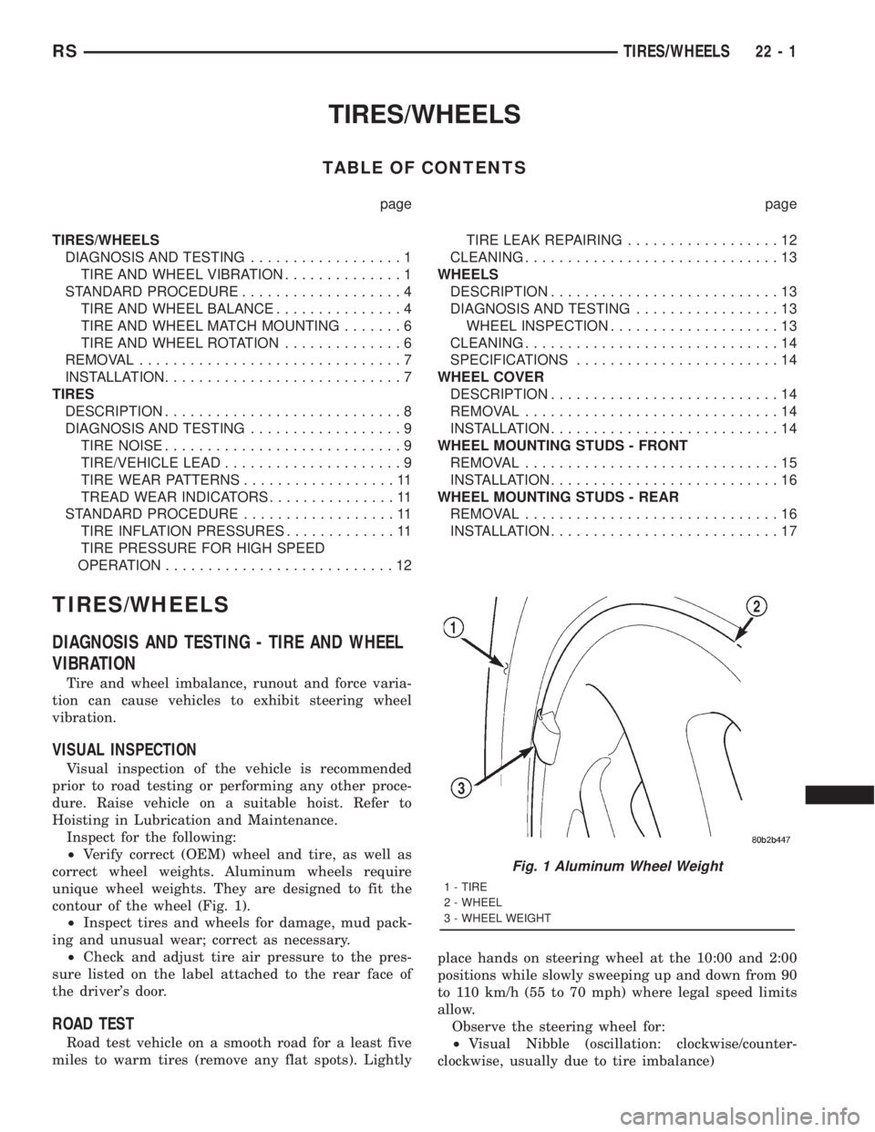
contour of the wheel (Fig. 1).
²Inspect tires and wheels for damage, mud pack-
ing and unusual wear; correct as necessary.
²Check and adjust tire air pressure to the pres-
sure listed on the label attached to the rear face of
the driver's door.
ROAD TEST
Road test vehicle on a smooth road for a least five
miles to warm tires (remove any flat spots). Lightlyplace hands on steering wheel at the 10:00 and 2:00
positions while slowly sweeping up and down from 90
to 110 km/h (55 to 70 mph) where legal speed limits
allow.
Observe the steering wheel for:
²Visual Nibble (oscillation: clockwise/counter-
clockwise, usually due to tire imbalance)
Fig. 1 Aluminum Wheel Weight
1 - TIRE
2 - WHEEL
3 - WHEEL WEIGHT
RSTIRES/WHEELS22-1
Page 3371 of 4284
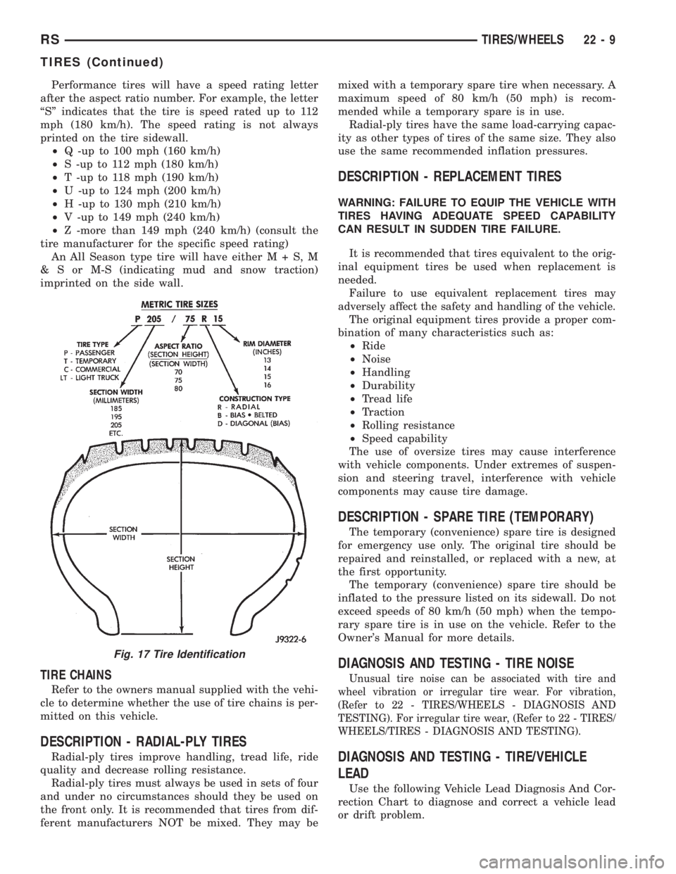
Performance tires will have a speed rating letter
after the aspect ratio number. For example, the letter
ªSº indicates that the tire is speed rated up to 112
mph (180 km/h). The speed rating is not always
printed on the tire sidewall.
²Q -up to 100 mph (160 km/h)
²S -up to 112 mph (180 km/h)
²T -up to 118 mph (190 km/h)
²U -up to 124 mph (200 km/h)
²H -up to 130 mph (210 km/h)
²V -up to 149 mph (240 km/h)
²Z -more than 149 mph (240 km/h) (consult the
tire manufacturer for the specific speed rating)
An All Season type tire will have eitherM+S,M
& S or M-S (indicating mud and snow traction)
imprinted on the side wall.
TIRE CHAINS
Refer to the owners manual supplied with the vehi-
cle to determine whether the use of tire chains is per-
mitted on this vehicle.
DESCRIPTION - RADIAL-PLY TIRES
Radial-ply tires improve handling, tread life, ride
quality and decrease rolling resistance.
Radial-ply tires must always be used in sets of four
and under no circumstances should they be used on
the front only. It is recommended that tires from dif-
ferent manufacturers NOT be mixed. They may bemixed with a temporary spare tire when necessary. A
maximum speed of 80 km/h (50 mph) is recom-
mended while a temporary spare is in use.
Radial-ply tires have the same load-carrying capac-
ity as other types of tires of the same size. They also
use the same recommended inflation pressures.
DESCRIPTION - REPLACEMENT TIRES
WARNING: FAILURE TO EQUIP THE VEHICLE WITH
TIRES HAVING ADEQUATE SPEED CAPABILITY
CAN RESULT IN SUDDEN TIRE FAILURE.
It is recommended that tires equivalent to the orig-
inal equipment tires be used when replacement is
needed.
Failure to use equivalent replacement tires may
adversely affect the safety and handling of the vehicle.
The original equipment tires provide a proper com-
bination of many characteristics such as:
²Ride
²Noise
²Handling
²Durability
²Tread life
²Traction
²Rolling resistance
²Speed capability
The use of oversize tires may cause interference
with vehicle components. Under extremes of suspen-
sion and steering travel, interference with vehicle
components may cause tire damage.
DESCRIPTION - SPARE TIRE (TEMPORARY)
The temporary (convenience) spare tire is designed
for emergency use only. The original tire should be
repaired and reinstalled, or replaced with a new, at
the first opportunity.
The temporary (convenience) spare tire should be
inflated to the pressure listed on its sidewall. Do not
exceed speeds of 80 km/h (50 mph) when the tempo-
rary spare tire is in use on the vehicle. Refer to the
Owner's Manual for more details.
DIAGNOSIS AND TESTING - TIRE NOISE
Unusual tire noise can be associated with tire and
wheel vibration or irregular tire wear. For vibration,
(Refer to 22 - TIRES/WHEELS - DIAGNOSIS AND
TESTING). For irregular tire wear, (Refer to 22 - TIRES/
WHEELS/TIRES - DIAGNOSIS AND TESTING).
DIAGNOSIS AND TESTING - TIRE/VEHICLE
LEAD
Use the following Vehicle Lead Diagnosis And Cor-
rection Chart to diagnose and correct a vehicle lead
or drift problem.
Fig. 17 Tire Identification
RSTIRES/WHEELS22-9
TIRES (Continued)
Page 3373 of 4284
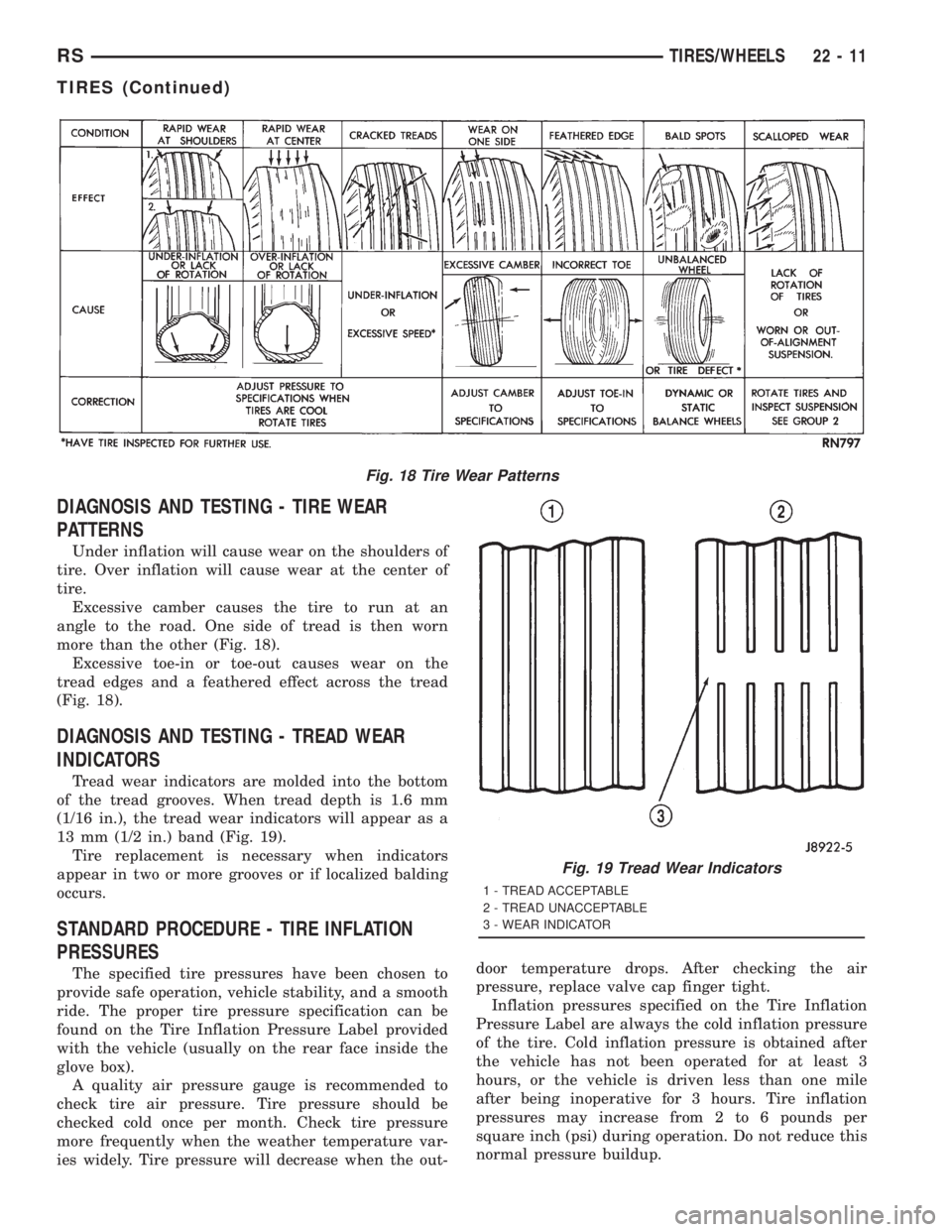
DIAGNOSIS AND TESTING - TIRE WEAR
PATTERNS
Under inflation will cause wear on the shoulders of
tire. Over inflation will cause wear at the center of
tire.
Excessive camber causes the tire to run at an
angle to the road. One side of tread is then worn
more than the other (Fig. 18).
Excessive toe-in or toe-out causes wear on the
tread edges and a feathered effect across the tread
(Fig. 18).
DIAGNOSIS AND TESTING - TREAD WEAR
INDICATORS
Tread wear indicators are molded into the bottom
of the tread grooves. When tread depth is 1.6 mm
(1/16 in.), the tread wear indicators will appear as a
13 mm (1/2 in.) band (Fig. 19).
Tire replacement is necessary when indicators
appear in two or more grooves or if localized balding
occurs.
STANDARD PROCEDURE - TIRE INFLATION
PRESSURES
The specified tire pressures have been chosen to
provide safe operation, vehicle stability, and a smooth
ride. The proper tire pressure specification can be
found on the Tire Inflation Pressure Label provided
with the vehicle (usually on the rear face inside the
glove box).
A quality air pressure gauge is recommended to
check tire air pressure. Tire pressure should be
checked cold once per month. Check tire pressure
more frequently when the weather temperature var-
ies widely. Tire pressure will decrease when the out-door temperature drops. After checking the air
pressure, replace valve cap finger tight.
Inflation pressures specified on the Tire Inflation
Pressure Label are always the cold inflation pressure
of the tire. Cold inflation pressure is obtained after
the vehicle has not been operated for at least 3
hours, or the vehicle is driven less than one mile
after being inoperative for 3 hours. Tire inflation
pressures may increase from 2 to 6 pounds per
square inch (psi) during operation. Do not reduce this
normal pressure buildup.
Fig. 18 Tire Wear Patterns
Fig. 19 Tread Wear Indicators
1 - TREAD ACCEPTABLE
2 - TREAD UNACCEPTABLE
3 - WEAR INDICATOR
RSTIRES/WHEELS22-11
TIRES (Continued)
Page 3374 of 4284
Improper inflation can cause:
²Uneven wear patterns
²Reduced tread life
²Reduced fuel economy
²Unsatisfactory ride
²The vehicle to drift.
WARNING: OVER OR UNDER INFLATED TIRES CAN
AFFECT VEHICLE HANDLING. THE TIRE CAN FAIL
SUDDENLY, RESULTING IN LOSS OF VEHICLE
CONTROL.
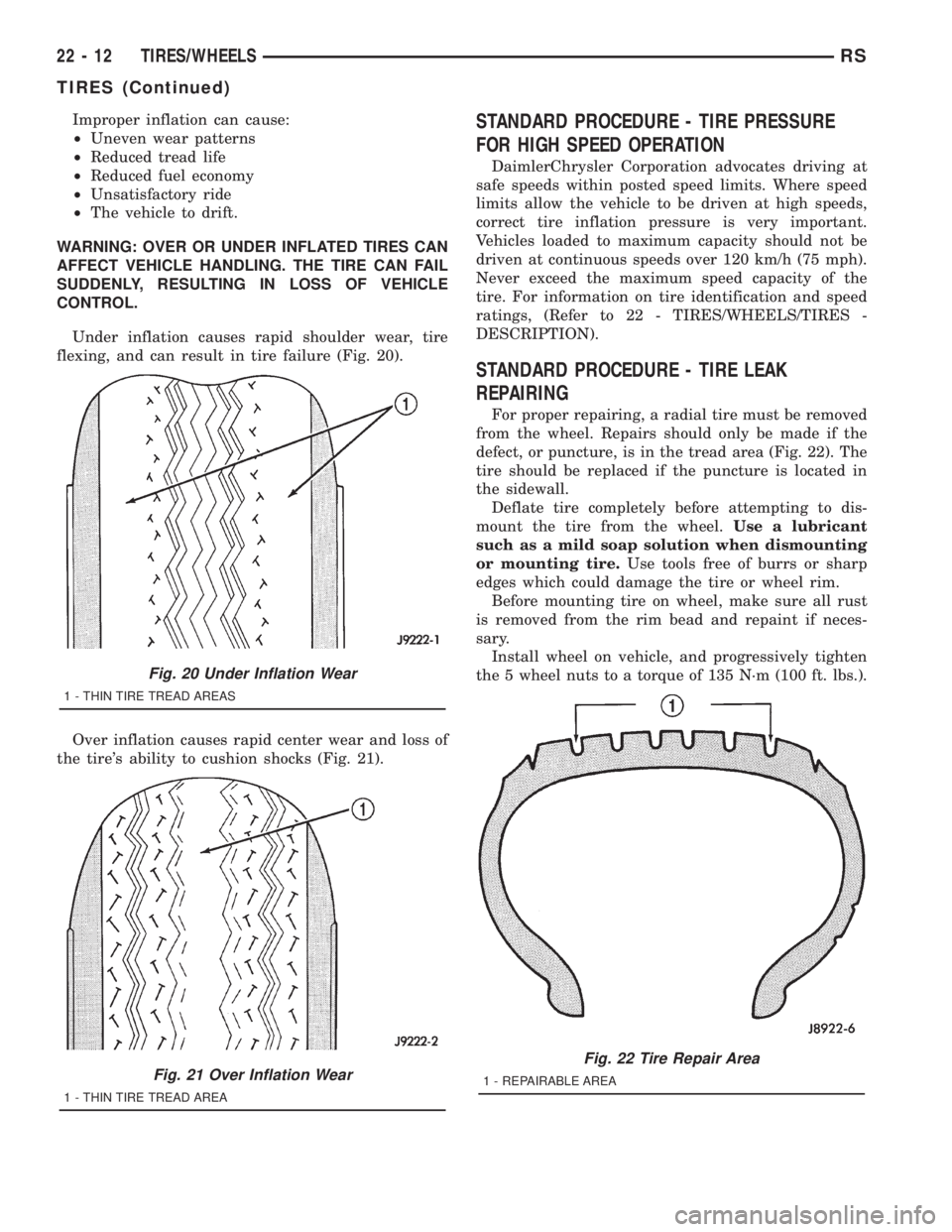
Under inflation causes rapid shoulder wear, tire
flexing, and can result in tire failure (Fig. 20).
Over inflation causes rapid center wear and loss of
the tire's ability to cushion shocks (Fig. 21).STANDARD PROCEDURE - TIRE PRESSURE
FOR HIGH SPEED OPERATION
DaimlerChrysler Corporation advocates driving at
safe speeds within posted speed limits. Where speed
limits allow the vehicle to be driven at high speeds,
correct tire inflation pressure is very important.
Vehicles loaded to maximum capacity should not be
driven at continuous speeds over 120 km/h (75 mph).
Never exceed the maximum speed capacity of the
tire. For information on tire identification and speed
ratings, (Refer to 22 - TIRES/WHEELS/TIRES -
DESCRIPTION).
STANDARD PROCEDURE - TIRE LEAK
REPAIRING
For proper repairing, a radial tire must be removed
from the wheel. Repairs should only be made if the
defect, or puncture, is in the tread area (Fig. 22). The
tire should be replaced if the puncture is located in
the sidewall.
Deflate tire completely before attempting to dis-
mount the tire from the wheel.Use a lubricant
such as a mild soap solution when dismounting
or mounting tire.Use tools free of burrs or sharp
edges which could damage the tire or wheel rim.
Before mounting tire on wheel, make sure all rust
is removed from the rim bead and repaint if neces-
sary.
Install wheel on vehicle, and progressively tighten
the 5 wheel nuts to a torque of 135 N´m (100 ft. lbs.).
Fig. 20 Under Inflation Wear
1 - THIN TIRE TREAD AREAS
Fig. 21 Over Inflation Wear
1 - THIN TIRE TREAD AREA
Fig. 22 Tire Repair Area
1 - REPAIRABLE AREA
22 - 12 TIRES/WHEELSRS
TIRES (Continued)