2001 CHRYSLER VOYAGER torque
[x] Cancel search: torquePage 3618 of 4284
SEAT BACK HINGE COVERS -
QUAD BUCKET, 50/50 SPLIT,
BENCH
REMOVAL
(1) Remove seat from vehicle. Refer to Owner's
Manual for proper procedures.
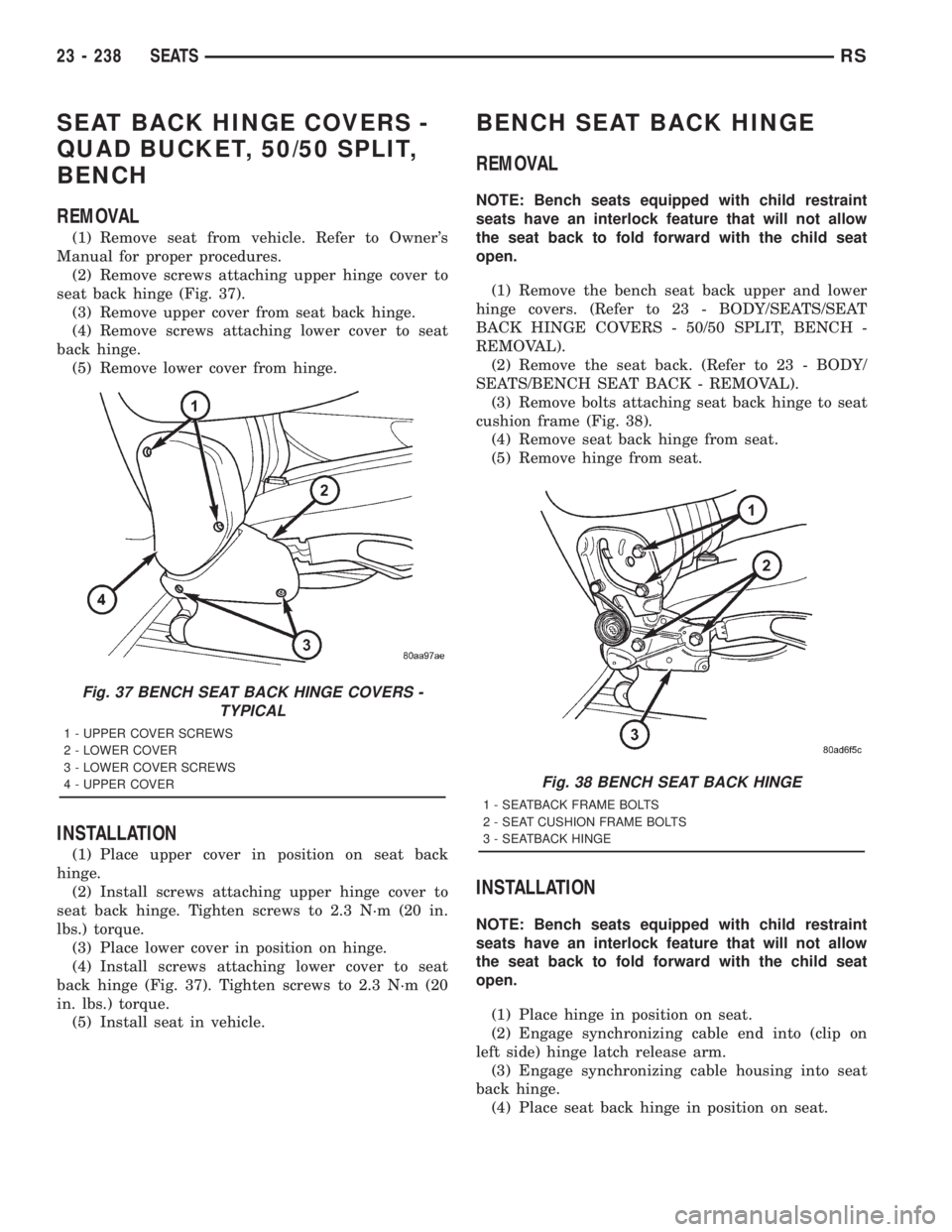
(2) Remove screws attaching upper hinge cover to
seat back hinge (Fig. 37).
(3) Remove upper cover from seat back hinge.
(4) Remove screws attaching lower cover to seat
back hinge.
(5) Remove lower cover from hinge.
INSTALLATION
(1) Place upper cover in position on seat back
hinge.
(2) Install screws attaching upper hinge cover to
seat back hinge. Tighten screws to 2.3 N´m (20 in.
lbs.) torque.
(3) Place lower cover in position on hinge.
(4) Install screws attaching lower cover to seat
back hinge (Fig. 37). Tighten screws to 2.3 N´m (20
in. lbs.) torque.
(5) Install seat in vehicle.
BENCH SEAT BACK HINGE
REMOVAL
NOTE: Bench seats equipped with child restraint
seats have an interlock feature that will not allow
the seat back to fold forward with the child seat
open.
(1) Remove the bench seat back upper and lower
hinge covers. (Refer to 23 - BODY/SEATS/SEAT
BACK HINGE COVERS - 50/50 SPLIT, BENCH -
REMOVAL).
(2) Remove the seat back. (Refer to 23 - BODY/
SEATS/BENCH SEAT BACK - REMOVAL).
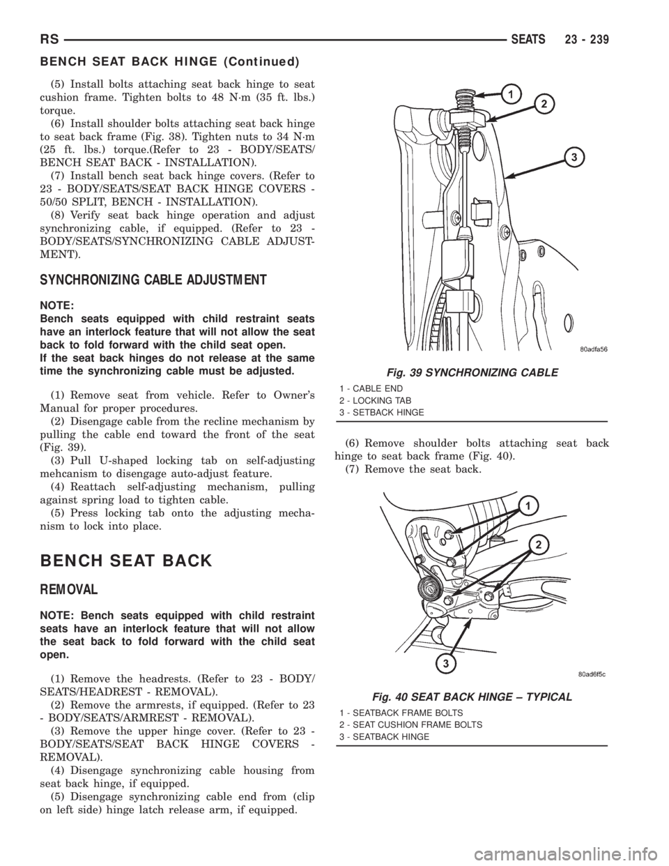
(3) Remove bolts attaching seat back hinge to seat
cushion frame (Fig. 38).
(4) Remove seat back hinge from seat.
(5) Remove hinge from seat.
INSTALLATION
NOTE: Bench seats equipped with child restraint
seats have an interlock feature that will not allow
the seat back to fold forward with the child seat
open.
(1) Place hinge in position on seat.
(2) Engage synchronizing cable end into (clip on
left side) hinge latch release arm.
(3) Engage synchronizing cable housing into seat
back hinge.
(4) Place seat back hinge in position on seat.
Fig. 37 BENCH SEAT BACK HINGE COVERS -
TYPICAL
1 - UPPER COVER SCREWS
2 - LOWER COVER
3 - LOWER COVER SCREWS
4 - UPPER COVER
Fig. 38 BENCH SEAT BACK HINGE
1 - SEATBACK FRAME BOLTS
2 - SEAT CUSHION FRAME BOLTS
3 - SEATBACK HINGE
23 - 238 SEATSRS
Page 3619 of 4284
(5) Install bolts attaching seat back hinge to seat
cushion frame. Tighten bolts to 48 N´m (35 ft. lbs.)
torque.
(6) Install shoulder bolts attaching seat back hinge
to seat back frame (Fig. 38). Tighten nuts to 34 N´m
(25 ft. lbs.) torque.(Refer to 23 - BODY/SEATS/
BENCH SEAT BACK - INSTALLATION).
(7) Install bench seat back hinge covers. (Refer to
23 - BODY/SEATS/SEAT BACK HINGE COVERS -
50/50 SPLIT, BENCH - INSTALLATION).
(8) Verify seat back hinge operation and adjust
synchronizing cable, if equipped. (Refer to 23 -
BODY/SEATS/SYNCHRONIZING CABLE ADJUST-
MENT).
SYNCHRONIZING CABLE ADJUSTMENT
NOTE:
Bench seats equipped with child restraint seats
have an interlock feature that will not allow the seat
back to fold forward with the child seat open.
If the seat back hinges do not release at the same
time the synchronizing cable must be adjusted.
(1) Remove seat from vehicle. Refer to Owner's
Manual for proper procedures.
(2) Disengage cable from the recline mechanism by
pulling the cable end toward the front of the seat
(Fig. 39).
(3) Pull U-shaped locking tab on self-adjusting
mehcanism to disengage auto-adjust feature.
(4) Reattach self-adjusting mechanism, pulling
against spring load to tighten cable.
(5) Press locking tab onto the adjusting mecha-
nism to lock into place.
BENCH SEAT BACK
REMOVAL
NOTE: Bench seats equipped with child restraint
seats have an interlock feature that will not allow
the seat back to fold forward with the child seat
open.
(1) Remove the headrests. (Refer to 23 - BODY/
SEATS/HEADREST - REMOVAL).
(2) Remove the armrests, if equipped. (Refer to 23
- BODY/SEATS/ARMREST - REMOVAL).
(3) Remove the upper hinge cover. (Refer to 23 -
BODY/SEATS/SEAT BACK HINGE COVERS -
REMOVAL).
(4) Disengage synchronizing cable housing from
seat back hinge, if equipped.
(5) Disengage synchronizing cable end from (clip
on left side) hinge latch release arm, if equipped.(6) Remove shoulder bolts attaching seat back
hinge to seat back frame (Fig. 40).
(7) Remove the seat back.
Fig. 39 SYNCHRONIZING CABLE
1 - CABLE END
2 - LOCKING TAB
3 - SETBACK HINGE
Fig. 40 SEAT BACK HINGE ± TYPICAL
1 - SEATBACK FRAME BOLTS
2 - SEAT CUSHION FRAME BOLTS
3 - SEATBACK HINGE
RSSEATS23 - 239
BENCH SEAT BACK HINGE (Continued)
Page 3620 of 4284
INSTALLATION
NOTE: Bench seats equipped with child restraint
seats have an interlock feature that will not allow
the seat back to fold forward with the child seat
open.
(1) Install the seat back.
(2) Install the shoulder bolts attaching the seat
back hinge to the seat back frame and tighten to 34
N´m (25 ft. lbs.) torque.
(3) Connect the synchronizing cable end from (clip
on left side) hinge latch release arm, if equipped.
(4) Connect the synchronizing cable housing to the
seat back hinge, if equipped.
(5) Install the upper hinge cover. (Refer to 23 -
BODY/SEATS/SEAT BACK HINGE - INSTALLA-
TION).
(6) Install the armrests, if equipped. (Refer to 23 -
BODY/SEATS/ARMREST - INSTALLATION).
(7) Install the headrest sleeves. (Refer to 23 -
BODY/SEATS/HEADREST SLEEVE - INSTALLA-
TION).
(8) Adjust synchronizing cable, if equipped. (Refer
to 23 - BODY/SEATS/SYNCHRONIZING CABLE
ADJUSTMENT).
BENCH SEAT BACK COVER
REMOVAL
(1) Remove the bench seat back. (Refer to 23 -
BODY/SEATS/BENCH SEAT BACK - REMOVAL).
(2) Remove the bench seatback panel. (Refer to 23
- BODY/SEATS/BENCH SEATBACK PANEL -
REMOVAL).
(3) Disconnect the cover J-straps.
(4) Remove the seat back cover from the seat back
assembly.
INSTALLATION
(1) Install seat back cover onto the seat back
frame and cushion assembly.
(2) Connect the J-straps.
(3) Install the bench seatback panel. (Refer to 23 -
BODY/SEATS/BENCH SEATBACK PANEL -
INSTALLATION).
(4) Install the seat back. (Refer to 23 - BODY/
SEATS/BENCH SEAT BACK - INSTALLATION).
BENCH SEAT TRACK
REMOVAL
(1) Remove second row seat from vehicle. Refer to
Owner's Manual for proper procedure.(2) Place seat on clean covered work surface.
(3) Disengage seat track adjuster link wire from
track being removed.
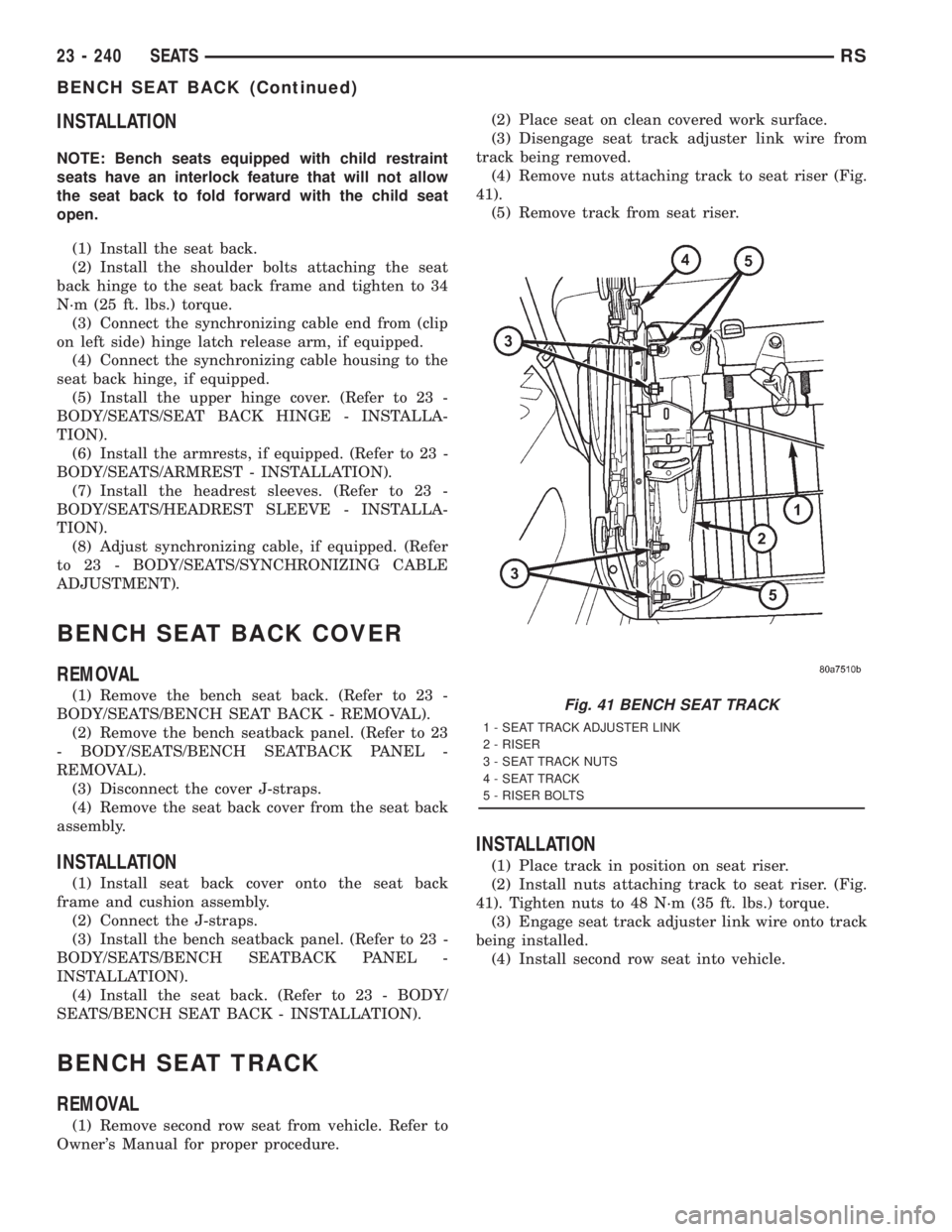
(4) Remove nuts attaching track to seat riser (Fig.
41).
(5) Remove track from seat riser.
INSTALLATION
(1) Place track in position on seat riser.
(2) Install nuts attaching track to seat riser. (Fig.
41). Tighten nuts to 48 N´m (35 ft. lbs.) torque.
(3) Engage seat track adjuster link wire onto track
being installed.
(4) Install second row seat into vehicle.
Fig. 41 BENCH SEAT TRACK
1 - SEAT TRACK ADJUSTER LINK
2 - RISER
3 - SEAT TRACK NUTS
4 - SEAT TRACK
5 - RISER BOLTS
23 - 240 SEATSRS
BENCH SEAT BACK (Continued)
Page 3621 of 4284
PLASTIC GROCERY BAG
RETAINER
REMOVAL
3-PASS BENCH SEAT
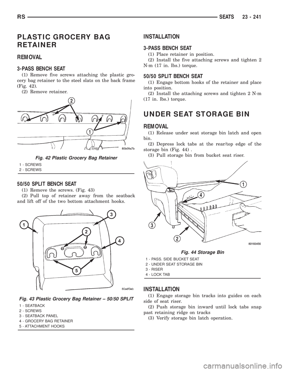
(1) Remove five screws attaching the plastic gro-
cery bag retainer to the steel slats on the back frame
(Fig. 42).
(2) Remove retainer.
50/50 SPLIT BENCH SEAT
(1) Remove the screws. (Fig. 43)
(2) Pull top of retainer away from the seatback
and lift off of the two bottom attachment hooks.
INSTALLATION
3-PASS BENCH SEAT
(1) Place retainer in position.
(2) Install the five attaching screws and tighten 2
N´m (17 in. lbs.) torque.
50/50 SPLIT BENCH SEAT
(1) Engage bottom hooks of the retainer and place
into position.
(2) Install the attaching screws and tighten 2 N´m
(17 in. lbs.) torque.
UNDER SEAT STORAGE BIN
REMOVAL
(1) Release under seat storage bin latch and open
bin.
(2) Depress lock tabs at the rear/top edge of the
storage bin (Fig. 44) .
(3) Pull storage bin from bucket seat riser.
INSTALLATION
(1) Engage storage bin tracks into guides on each
side of seat riser.
(2) Push storage bin inward until lock tabs snap
past retaining ridge on tracks
(3) Verify storage bin latch operation.
Fig. 42 Plastic Grocery Bag Retainer
1 - SCREWS
2 - SCREWS
Fig. 43 Plastic Grocery Bag Retainer ± 50/50 SPLIT
1 - SEATBACK
2 - SCREWS
3 - SEATBACK PANEL
4 - GROCERY BAG RETAINER
5 - ATTACHMENT HOOKS
Fig. 44 Storage Bin
1 - PASS. SIDE BUCKET SEAT
2 - UNDER SEAT STORAGE BIN
3 - RISER
4 - LOCK TAB
RSSEATS23 - 241
Page 3622 of 4284
UNDER SEAT STORAGE BIN
GUIDE
REMOVAL
(1) Remove under seat storage bin. (Refer to 23 -
BODY/SEATS/UNDER SEAT STORAGE BIN -
REMOVAL).
(2) Remove screws attaching storage bin track
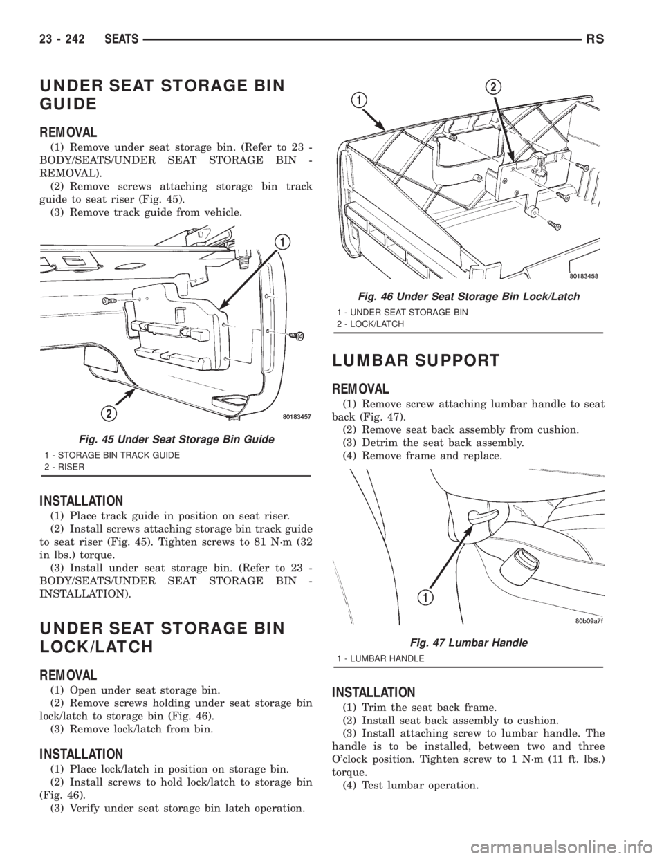
guide to seat riser (Fig. 45).
(3) Remove track guide from vehicle.
INSTALLATION
(1) Place track guide in position on seat riser.
(2) Install screws attaching storage bin track guide
to seat riser (Fig. 45). Tighten screws to 81 N´m (32
in lbs.) torque.
(3) Install under seat storage bin. (Refer to 23 -
BODY/SEATS/UNDER SEAT STORAGE BIN -
INSTALLATION).
UNDER SEAT STORAGE BIN
LOCK/LATCH
REMOVAL
(1) Open under seat storage bin.
(2) Remove screws holding under seat storage bin
lock/latch to storage bin (Fig. 46).
(3) Remove lock/latch from bin.
INSTALLATION
(1) Place lock/latch in position on storage bin.
(2) Install screws to hold lock/latch to storage bin
(Fig. 46).
(3) Verify under seat storage bin latch operation.
LUMBAR SUPPORT
REMOVAL
(1) Remove screw attaching lumbar handle to seat
back (Fig. 47).
(2) Remove seat back assembly from cushion.
(3) Detrim the seat back assembly.
(4) Remove frame and replace.
INSTALLATION
(1) Trim the seat back frame.
(2) Install seat back assembly to cushion.
(3) Install attaching screw to lumbar handle. The
handle is to be installed, between two and three
O'clock position. Tighten screw to 1 N´m (11 ft. lbs.)
torque.
(4) Test lumbar operation.
Fig. 45 Under Seat Storage Bin Guide
1 - STORAGE BIN TRACK GUIDE
2 - RISER
Fig. 46 Under Seat Storage Bin Lock/Latch
1 - UNDER SEAT STORAGE BIN
2 - LOCK/LATCH
Fig. 47 Lumbar Handle
1 - LUMBAR HANDLE
23 - 242 SEATSRS
Page 3625 of 4284
(15) Clean access urethane from exterior with
Moparž Super Kleen or equivalent.
(16) Apply 150 mm (6 in.) lengths of 50 mm (2 in.)
masking tape spaced 250 mm (10 in.) apart to hold
molding in place until urethane cures.
(17) Engage wire connectors to windshield
defroster grid.
(18) Install A-pillar trim panels.
(19) Install cowl cover and wipers.
(20) Install inside rear view mirror.
(21) After urethane has cured, remove tape strips
and water test windshield to verify repair.SLIDING DOOR GLASS
REMOVAL
The temperature of the vehicle should be at least
21É C (70É F) before removing the stationary quarter/
sliding door glass. Butyl sealer becomes more pliable
at high temperatures.
(1) Remove interior trim as necessary to gain
access attaching locations on back of glass.
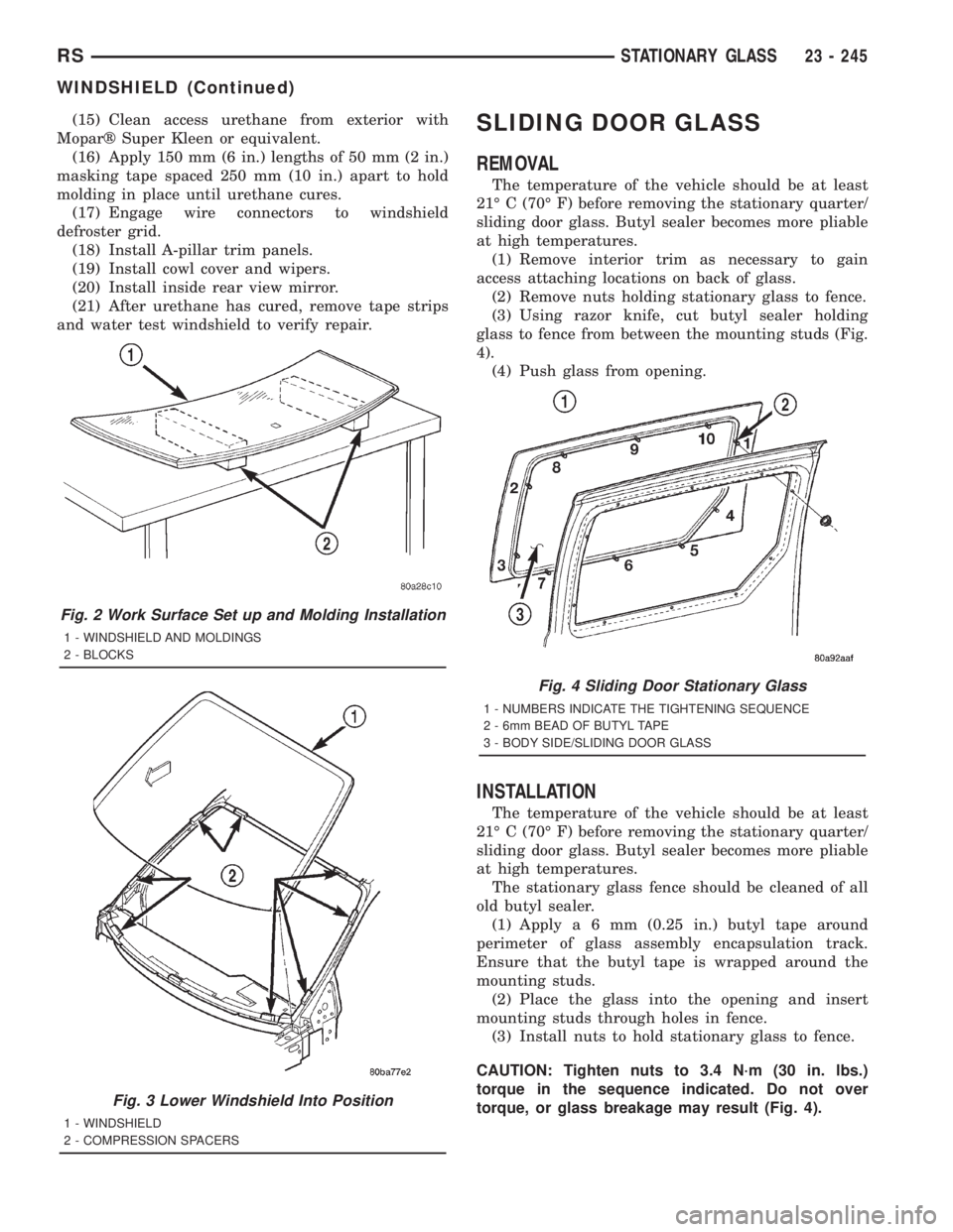
(2) Remove nuts holding stationary glass to fence.
(3) Using razor knife, cut butyl sealer holding
glass to fence from between the mounting studs (Fig.
4).
(4) Push glass from opening.
INSTALLATION
The temperature of the vehicle should be at least
21É C (70É F) before removing the stationary quarter/
sliding door glass. Butyl sealer becomes more pliable
at high temperatures.
The stationary glass fence should be cleaned of all
old butyl sealer.
(1) Applya6mm(0.25 in.) butyl tape around
perimeter of glass assembly encapsulation track.
Ensure that the butyl tape is wrapped around the
mounting studs.
(2) Place the glass into the opening and insert
mounting studs through holes in fence.
(3) Install nuts to hold stationary glass to fence.
CAUTION: Tighten nuts to 3.4 N´m (30 in. lbs.)
torque in the sequence indicated. Do not over
torque, or glass breakage may result (Fig. 4).
Fig. 2 Work Surface Set up and Molding Installation
1 - WINDSHIELD AND MOLDINGS
2 - BLOCKS
Fig. 3 Lower Windshield Into Position
1 - WINDSHIELD
2 - COMPRESSION SPACERS
Fig. 4 Sliding Door Stationary Glass
1 - NUMBERS INDICATE THE TIGHTENING SEQUENCE
2 - 6mm BEAD OF BUTYL TAPE
3 - BODY SIDE/SLIDING DOOR GLASS
RSSTATIONARY GLASS23 - 245
WINDSHIELD (Continued)
Page 3648 of 4284
ELECTRICAL/ELECTRONIC CONTROL MOD-
ULES/POWERTRAIN CONTROL MODULE -
DESCRIPTION - PCM OPERATION).
STANDARD PROCEDURE - COMPRESSOR
CLUTCH AIR GAP
If a new clutch plate and/or clutch pulley are being
used, the air gap between the clutch plate and clutch
pulley must be checked using the following proce-
dure:
(1) Using feeler gauges, measure the air gap
between the clutch plate and the clutch pulley fric-
tion surfaces.
(2) If the air gap is not between 0.5 and 0.9 mm
(0.020 and 0.035 in.), add or subtract shims until the
desired air gap is obtained.
NOTE: The shims may compress after tightening
the compressor shaft bolt. Check the air gap in four
or more places on the clutch plate to verify that the
air gap is still correct. Spin the clutch pulley before
making the final air gap check.
STANDARD PROCEDURE - COMPRESSOR
CLUTCH BREAK-IN
After a new compressor clutch has been installed,
check that the compressor clutch coil is performing to
specifications. (Refer to 24 - HEATING & AIR CON-
DITIONING/CONTROLS - FRONT/COMPRESSOR
CLUTCH COIL - DIAGNOSIS AND TESTING). If
the clutch coil is performing to specifications, per-
form the compressor clutch break-in procedure. This
procedure (burnishing) will seat the opposing friction
surfaces and provide a higher compressor clutch
torque capability.
(1) Set the heater-A/C controls to the A/C mode,
with the blower switch in the highest speed position.
(2) Start the engine and hold the engine speed at
1500 to 2000 rpm.
(3) Cycle the compressor clutch On and Off about
twenty times (five seconds On, then five seconds Off).
REMOVAL
The refrigerant system can remain fully charged
during compressor clutch, pulley, or coil replacement.
Although the compressor assembly must be removed
from its mounting, the compressor clutch can be ser-
vice with the compressor in the vehicle.
(1) Disconnect and isolate the battery negative
cable.
(2) Raise and support the vehicle.
(3) Remove the serpentine drive belt. (Refer to 7 -
COOLING/ACCESSORY DRIVE/DRIVE BELTS -
2.4L - REMOVAL) or (Refer to 7 - COOLING/ACCES-SORY DRIVE/DRIVE BELTS - 3.3/3.8L - REMOV-
AL).
(4) Disconnect the engine wire harness connector
for the compressor clutch coil from the clutch coil pig-
tail wire connector on the top of the compressor.
(5) On models with the 3.3L and 3.8L engines, dis-
engage the retainer on the engine wire harness com-
pressor clutch coil take out from the bracket on the
top of the compressor.
(6) On models with the 2.4L engine, remove all of
the compressor mounting screws except the upper
left (rear of the compressor) screw, which should only
be loosened. Allow the front (pulley end) of the com-
pressor to tilt downward far enough to access the
clutch for removal, then tighten the loosened upper
left compressor mounting screw.
(7) On models with the 3.3L and 3.8L engines,
remove the three screws and one nut that secure the
compressor to the engine. Disengage the mounting
ear at the front of the compressor from the stud on
the engine, allow the front (pulley end) of the com-
pressor to tilt downward far enough to access the
clutch for removal, then reinstall and tighten the
upper left compressor mounting screw.
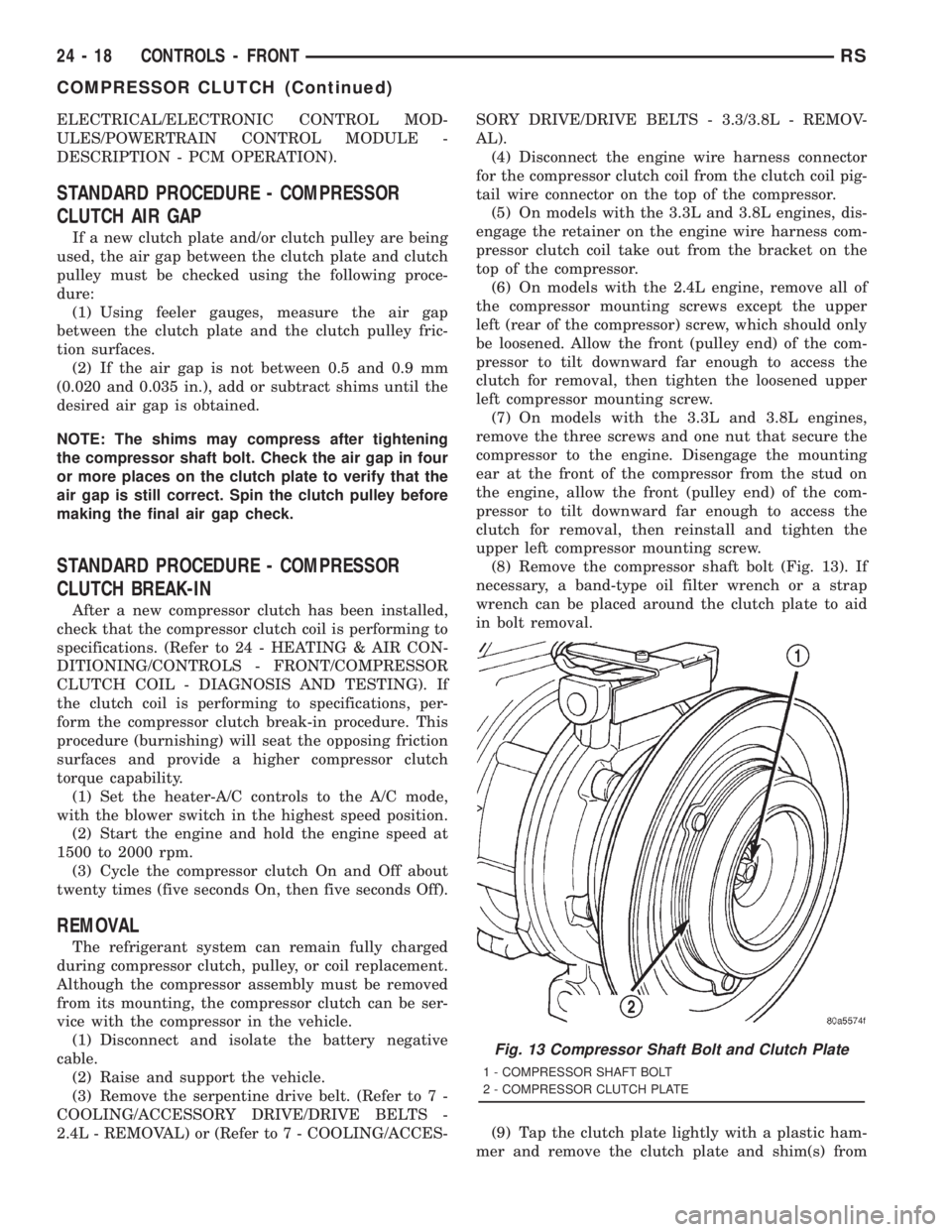
(8) Remove the compressor shaft bolt (Fig. 13). If
necessary, a band-type oil filter wrench or a strap
wrench can be placed around the clutch plate to aid
in bolt removal.
(9) Tap the clutch plate lightly with a plastic ham-
mer and remove the clutch plate and shim(s) from
Fig. 13 Compressor Shaft Bolt and Clutch Plate
1 - COMPRESSOR SHAFT BOLT
2 - COMPRESSOR CLUTCH PLATE
24 - 18 CONTROLS - FRONTRS
COMPRESSOR CLUTCH (Continued)
Page 3694 of 4284
CAUTION: Do not overcharge the refrigerant sys-
tem. This will cause excessive compressor head
pressure and can cause noise and system failure.
CAUTION: Do not open the refrigerant system or
remove the sealing caps from a replacement com-
ponent until it is to be installed. This will prevent
contamination in the system.
CAUTION: Before disconnecting a component,
clean the outside of the fittings thoroughly to pre-
vent contamination from entering the refrigerant
system.
CAUTION: When it is necessary to open the refrig-
erant system, have everything needed to service
the system ready. Immediately after disconnecting a
component from the refrigerant system, seal the
open fittings with a cap or plug to prevent the
entrance of dirt and moisture. The refrigerant sys-
tem should not be left open to the atmosphere any
longer than necessary.
CAUTION: Before connecting an open refrigerant
fitting, always install a new seal or gasket. All fit-
tings with O-rings need to be coated with refriger-
ant oil before installation. Use only O-rings that are
the correct size and approved for use with R-134a
refrigerant. Failure to do so may result in a leak.
Coat the fitting and seal with clean refrigerant oil
before connecting. Unified plumbing connections
with gaskets cannot be serviced with O-rings. The
gaskets are not reusable and new gaskets do not
require lubrication before installing.
CAUTION: When installing a refrigerant line, avoid
sharp bends that may restrict refrigerant flow. A
good rule for the flexible hose refrigerant lines is to
keep the radius of all bends at least ten times the
diameter of the hose. Sharp bends will reduce the
flow of refrigerant.
CAUTION: Position the refrigerant lines away from
exhaust system components or any sharp edges,
which may damage the line. The flexible hose lines
should be routed so they are at least 80 millimeters
(3 inches) from the exhaust manifold. Inspect all
flexible refrigerant system hose lines at least once
a year to make sure they are in good condition and
properly routed.CAUTION: High pressures are produced in the
refrigerant system when it is operating. Extreme
care must be exercised to make sure that all refrig-
erant system connections are pressure tight.
CAUTION: Tighten refrigerant fittings only to the
specified torque. The aluminum fittings used in the
refrigerant system will not tolerate overtightening.
CAUTION: When disconnecting a refrigerant fitting,
use a wrench on both halves of the fitting. This will
prevent twisting of the refrigerant lines or tubes.
CAUTION: Refrigerant oil will absorb moisture from
the atmosphere if left uncapped. Do not open a
container of refrigerant oil until you are ready to
use it. Replace the cap on the oil container immedi-
ately after using. Store refrigerant oil only in a
clean, airtight, and moisture-free container.
CAUTION: All tools, including the refrigerant recy-
cling equipment, the manifold gauge set, and test
hoses should be kept clean and dry. Keep the work
area clean. Contamination of the refrigerant system
through careless work habits must be avoided. The
refrigerant system will remain chemically stable as
long as pure, moisture-free R-134a refrigerant and
refrigerant oil is used. Dirt, moisture, or air can
upset this chemical stability. Operational troubles
or serious damage can occur if foreign material is
introduced to the refrigerant system.
COMPRESSOR
DESCRIPTION
The compressor used on this vehicle can be one of
two models, depending upon the air conditioning sys-
tem in the vehicle. All vehicles use the Nippondenso
10S20H compressor. This compressor use an alumi-
num swash plate, teflon coated pistons and alumi-
num sleeveless cylinder walls. This compressor
includes an integral high pressure relief valve. The
compressor is secured low in the right front corner of
the engine compartment to a mounting bracket on
the cylinder block (2.4L engine), or directly to the cyl-
inder block (3.3L and 3.8L engines).is integral to the
compressor. This compressor cannot be repaired. If
faulty or damaged, the entire compressor must be
replaced. The compressor clutch, pulley, and clutch
coil are available for service replacement.
24 - 64 PLUMBING - FRONTRS
PLUMBING - FRONT (Continued)