2001 CHRYSLER VOYAGER COOLING SYSTEM
[x] Cancel search: COOLING SYSTEMPage 45 of 4284
the CPA is not properly engaged, a voltage on pin 38
will be interpreted as an unseated connector and a
fault will set.
Flash programming voltage Ð20 volt input on
pin 42. When a DRBIIItis connected and the
proper flash reprogramming sequence is selected,
the 20 volt signal will be applied through pin 42.
3.9 HEATING & A/C
3.9.1 AUTOMATIC TEMPERATURE
CONTROL (ATC)
3.9.1.1 CABIN HEATER
For vehicles equipped with a diesel engine, a
Cabin Heater is used in conjunction with the HVAC
system. The Cabin Heater is designed to supply the
vehicle's occupants with heat prior to the engine
reaching operating temperature. For additional in-
formation on this system, refer to Cabin Heater
under General Information and Diagnostic Proce-
dures in this manual.
3.9.1.2 SYSTEM OPERATION
The Automatic Temperature Control (ATC) sys-
tem provides fully adjustable three zone climate
control; Driver front zone, Passenger Front zone
and Rear zone. The following is a list of ATC
controls and features:
± a POWER button which allows the operator to
turn the system completely off.
± AUTO HIGH/LOW switch allows the operator
to select what rate (fan speed) the system will
provide the selected comfort level.
± DRIVER, REAR and PASSENGER rocker
switches to select desired temperature for each
zone.
± Recirculation button allows cooling air to be
recirculated which maximizes cooling ability.
± A/C select button allows the operator to turn
the A/C compressor off.
± Defroster button allows the operator to turn on
the defroster independently during automatic
control.
± Fan control rotary switch for selecting fan
speed.
± Mode rotary switch for selecting heating/
cooling direction.
± REAR SYSTEM rotary switch for activating
the Rear ATC Switch allowing intermediate
passenger control over rear climate control.
3.9.1.3 BLOWER MOTOR OPERATION
The Automatic Temperature Control (ATC) front
and rear blower control provides continuously vari-
able control of air flow rate to meet occupant
comfort requirements. Pulse width modulation of
the blower motor power allows the front and rear
blower to operate at any speed from off to full speed.
When front or rear blower operation is required, the
ATC sends a PCI Bus message to the Front Control
Module (FCM) requesting blower relay ON. The
FCM provides a ground for the front and rear
blower motor relay coils, activating both relays. The
front and rear blower relays provide 12 volts to
their respective blower motor power modules. Each
module provides a 12 volt blower motor control
signal to the ATC. The ATC provides a pulse width
modulated (duty-cycle) ground signal to this circuit
based on climate requirements. The higher voltage
on the signal circuit (less duty-cycle ground) the
lower the blower speed request. The lower voltage
on the signal circuit (more duty-cycle ground) the
higher the blower speed request.
3.9.1.4 INFRARED SENSORS
The ATC system uses infrared (I/R) sensors to
monitor and control oocupant comfort levels. This
sensing system replaces interior air temperature
and solar sensors which required complex control
programs to maintain occupant comfort levels. The
front I/R sensor is located in the instrument panel
center bezel outlet. The rear I/R sensor is located in
the rear overhead mounted ATC switch.
3.9.1.5 REAR ATC SWITCH
The rear ATC switch is mounted in the headliner.
The switch contains a rotary adjustment for fan
speed, a rotary adjustment for mode selection, a
push button switch for temperature selection and a
digital display of the selected temperature.
3.9.1.6 COOLDOWN TESTING
The ATC provides a feature referred to as a
Cooldown Test. This test is initiated using the
DRBIIItand is designed to check the performance
of the air conditioning system. The ATC will not
perform this test if the ambient air temperature is
below 12ÉC (53ÉF). During the test, the ATC com-
pares the ambient air temperature to the evapora-
tor temperature sensor. To pass the cooldown test,
the evap temperature sensor must drop -6ÉC (20ÉF)
below ambient temperature within 2 minutes of
start of test. At the completion of the cooldown test
the DRBIIItwill display one of the following mes-
sages indicating test outcome:
± Cooldown Test Passed
± Cooldown Test Failed
16
GENERAL INFORMATION
Page 46 of 4284
± Evap Temp Sensor Shorted
± Evap Temp Sensor Open
± A/C Pressure Too Low
± A/C Pressure Too High
± Invalid Conditions for Cooldown Test, Evap
Temperature Too Low
If a message other than Cooldown Test Passed
occurs, refer to the appropriate symptom for diag-
nosis.
3.9.1.7 ACTIVE AND STORED TROUBLE
CODES
The Automatic Temperature Control (ATC) is
capable of storing Active and Stored trouble codes.
Active codes indicate a current fault in the system.
Stored codes indicate that a problem has occurred
in the system, however is not currently present.
Active codes cannot be erased until the problem
causing the code has been repaired. At this time the
Active code is converted to a Stored code, which can
be erased using the DRBIIIt.
3.9.2 MANUAL TEMPERATURE CONTROL
3.9.2.1 SYSTEM AVAILABILITY
Depending on the model, either a Single-Zone Air
Conditioning System or a Dual-Zone Air Condition-
ing System is currently available in these vehicles.
3.9.2.2 CABIN HEATER
For Vehicles equipped with a diesel engine, a
Cabin Heater is used in conjunction with the HVAC
system. The Cabin Heater is designed to supply the
vehicle's occupants with heat prior to the engine
reaching operating temperature. For additional in-
formation on this system, refer to Cabin Heater
under General Information and Diagnostic Proce-
dures in this manual.
3.9.2.3 ZONE CONTROL ± SINGLE-ZONE
The Single-Zone Air Conditioning System main-
tains incoming air temperature, airflow, fan speed,
and fresh air intake for the entire vehicle from the
instrument panel mounted A/C ± Heater Control
Module. The full range of temperature that the
system can produce in any mode for the entire
vehicle is available by positioning the blend control
to the desired range.
3.9.2.4 ZONE CONTROL ± DUAL-ZONE
The Dual-Zone Air Conditioning System main-
tains incoming air temperature, airflow, fan speed,
and fresh air intake for the entire vehicle from the
instrument panel mounted A/C ± Heater ControlModule. In addition, this system provides com-
pletely independent side-to-side control of incoming
air temperature. The full range of temperature that
the system can produce in any mode is available on
either side of the vehicle by positioning the inde-
pendent driver and passenger blend controls to the
desired range.
3.9.2.5 AIR DISTRIBUTION
The HVAC unit has five fully adjustable instru-
ment panel outlets. Side-window demister outlets
in the instrument panel eliminate door ducts and
door-to-instrument panel seals. A single, central
mounted outlet delivers air for defrosting the wind-
shield. Air exhausters allow air entering at the
front of the vehicle to flow out the back to the rear
occupants. Mid-cabin comfort control directs only
cooling air flow to the intermediate seat occupants
through outlets at the rear of each front door trim
panel. Air is supplied to these outlets from the
instrument panel through ducts in the doors that
use molded seals at the instrument panel to prevent
air leakage. Wide outlets under the front seats with
directional dividers distribute heated air across the
floor to the intermediate seat occupants. Ducts in
the center of the vehicle under the carpet deliver air
from the HVAC unit to these outlets. Models
equipped with Dual-Zone A/C systems also include
a dust and odor air filter installed in the HAVC
housing.
3.9.2.6 DOOR ACTUATORS
The electric door actuators are a two-wire design.
Each door actuator uses a similar connector wired
directly to the A/C ± Heater Control Module. Single-
Zone systems have one blend door actuator, one
mode door actuator, and one recirculation door
actuator. Dual-Zone systems have two blend door
actuators, one mode door actuator, and one recircu-
lation door actuator. All of the door actuators are
accessible from the vehicle's interior.
3.9.2.7 DOOR ACTUATOR CONTROL
The A/C ± Heater Control Module knows the
number of operating actuator revolutions required
for full door travel as well as the number of actuator
commutator pulses per revolution. Using these pa-
rameters, the A/C ± Heater Control Module runs
the actuator for the number of commutator pulses
that correspond to the desired door position. To
maintain accuracy, the system recalibrates itself
periodically at known zero and full travel condi-
tions.
17
GENERAL INFORMATION
Page 338 of 4284
Symptom:
B1811 HEATER OVERHEATED
When Monitored and Set Condition:
B1811 HEATER OVERHEATED
When Monitored: After DCHA activation, when the system is in a steady state of
operation.
Set Condition: This DTC will set if the Coolant Temperature Sensor resistance is not
within the expected parameters (coolant temperature in the Heater Module exceeds 125ÉC
[257ÉF]).
POSSIBLE CAUSES
DCHA HEATER MODULE FAULT
DCHA COOLANT HOSES RESTRICTED/LEAKING/DAMAGED
ENGINE'S COOLING SYSTEM FAULT
DCHA CONTROL UNIT FAULT
B1811 CLEARED, ADDITIONAL DTC(S) PRESENT
TEST ACTION APPLICABILITY
1WARNING: DO NOT OPERATE THE DCHA IN AN ENCLOSED AREA SUCH
AS A GARAGE THAT DOES NOT HAVE EXHAUST VENTILATION FACILI-
TIES. ALWAYS VENT THE DCHA's EXHAUST WHEN OPERATING THE
DCHA. FAILURE TO FOLLOW THESE INSTRUCTIONS MAY RESULT IN
PERSONAL INJURY OR DEATH.
WARNING: ALLOW THE DCHA ASSEMBLY TO COOL BEFORE PERFORM-
ING A COMPONENT INSPECTION/REPAIR/REPLACEMENT. FAILURE TO
FOLLOW THESE INSTRUCTIONS MAY RESULT IN PERSONAL INJURY.
CAUTION: DO NOT PERFORM THIS TEST UNLESS DIRECTED HERE BY
THE CABIN HEATER PRE-TEST. ALWAYS PERFORM THE CABIN HEATER
PRE-TEST PRIOR TO PERFORMING ANY OTHER CABIN HEATER TEST
FOR THE RESULT TO BE VALID.
Turn the ignition off.
NOTE: If there is an internal leak in the Heater Module, a continuous loud
chunking or grinding noise may have been heard coming from the DCHA
assembly during the Field Mode test.
Check for engine coolant continuously flowing out of the DCHA exhaust pipe.
Is engine coolant coming out of the DCHA exhaust pipe?All
Ye s®Replace the DCHA Heater Module in accordance with the Service
Information.
Perform CABIN HEATER VERIFICATION TEST - VER 1.
No®Go To 2
309
CABIN HEATER
Page 339 of 4284
TEST ACTION APPLICABILITY
2WARNING: DO NOT OPERATE THE DCHA IN AN ENCLOSED AREA SUCH
AS A GARAGE THAT DOES NOT HAVE EXHAUST VENTILATION FACILI-
TIES. ALWAYS VENT THE DCHA's EXHAUST WHEN OPERATING THE
DCHA. FAILURE TO FOLLOW THESE INSTRUCTIONS MAY RESULT IN
PERSONAL INJURY OR DEATH.
WARNING: ALLOW THE DCHA ASSEMBLY TO COOL BEFORE PERFORM-
ING A COMPONENT INSPECTION/REPAIR/REPLACEMENT. FAILURE TO
FOLLOW THESE INSTRUCTIONS MAY RESULT IN PERSONAL INJURY.
Turn the ignition off.
Inspect the DCHA coolant hoses for restrictions, leakage, and damage.
Are the DCHA coolant hoses Ok?All
Ye s®Go To 3
No®Repair the DCHA coolant hoses as necessary in accordance with
the Service Information.
Perform CABIN HEATER VERIFICATION TEST - VER 1.
3WARNING: DO NOT OPERATE THE DCHA IN AN ENCLOSED AREA SUCH
AS A GARAGE THAT DOES NOT HAVE EXHAUST VENTILATION FACILI-
TIES. ALWAYS VENT THE DCHA's EXHAUST WHEN OPERATING THE
DCHA. FAILURE TO FOLLOW THESE INSTRUCTIONS MAY RESULT IN
PERSONAL INJURY OR DEATH.
Check that the engine's cooling system is operating properly in accordance with the
Service Information.
Is the engine's cooling system operating properly?All
Ye s®Go To 4
No®Repair the engine's cooling system in accordance with the Service
Information.
Perform CABIN HEATER VERIFICATION TEST - VER 1.
4WARNING: DO NOT OPERATE THE DCHA IN AN ENCLOSED AREA SUCH
AS A GARAGE THAT DOES NOT HAVE EXHAUST VENTILATION FACILI-
TIES. ALWAYS VENT THE DCHA's EXHAUST WHEN OPERATING THE
DCHA. FAILURE TO FOLLOW THESE INSTRUCTIONS MAY RESULT IN
PERSONAL INJURY OR DEATH.
Start the engine.
Allow the engine to reach normal operating temperature.
Turn the engine off.
Allow the engine's coolant to cool down to a temperature of 50ÉC (122ÉF).
Start the engine.
Allow the engine to reach normal operating temperature.
Turn the engine off.
View repairAll
Repair
Go To 5
310
CABIN HEATER
B1811 HEATER OVERHEATED ÐContinued
Page 1020 of 4284
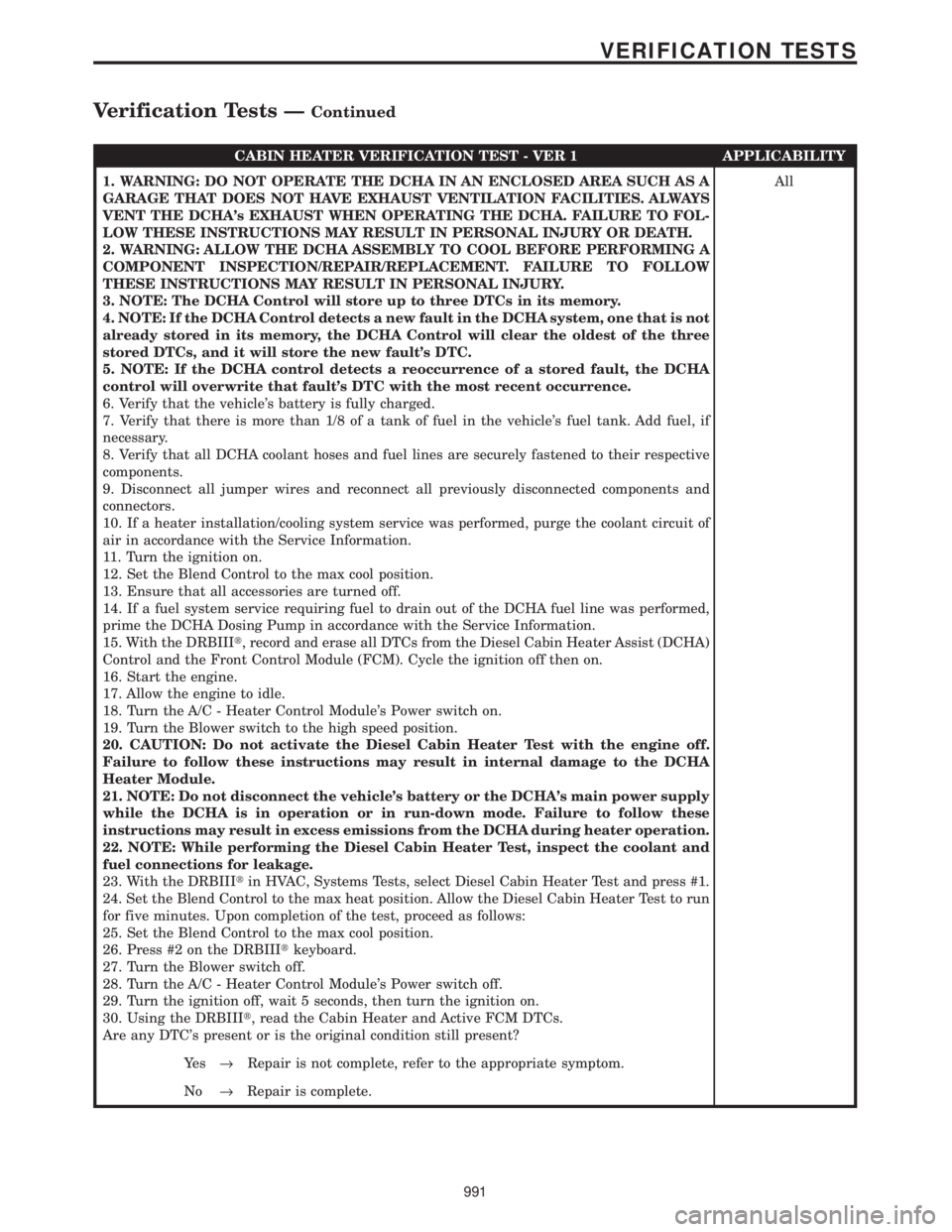
CABIN HEATER VERIFICATION TEST - VER 1 APPLICABILITY
1. WARNING: DO NOT OPERATE THE DCHA IN AN ENCLOSED AREA SUCH AS A
GARAGE THAT DOES NOT HAVE EXHAUST VENTILATION FACILITIES. ALWAYS
VENT THE DCHA's EXHAUST WHEN OPERATING THE DCHA. FAILURE TO FOL-
LOW THESE INSTRUCTIONS MAY RESULT IN PERSONAL INJURY OR DEATH.
2. WARNING: ALLOW THE DCHA ASSEMBLY TO COOL BEFORE PERFORMING A
COMPONENT INSPECTION/REPAIR/REPLACEMENT. FAILURE TO FOLLOW
THESE INSTRUCTIONS MAY RESULT IN PERSONAL INJURY.
3. NOTE: The DCHA Control will store up to three DTCs in its memory.
4. NOTE: If the DCHA Control detects a new fault in the DCHA system, one that is not
already stored in its memory, the DCHA Control will clear the oldest of the three
stored DTCs, and it will store the new fault's DTC.
5. NOTE: If the DCHA control detects a reoccurrence of a stored fault, the DCHA
control will overwrite that fault's DTC with the most recent occurrence.
6. Verify that the vehicle's battery is fully charged.
7. Verify that there is more than 1/8 of a tank of fuel in the vehicle's fuel tank. Add fuel, if
necessary.
8. Verify that all DCHA coolant hoses and fuel lines are securely fastened to their respective
components.
9. Disconnect all jumper wires and reconnect all previously disconnected components and
connectors.
10. If a heater installation/cooling system service was performed, purge the coolant circuit of
air in accordance with the Service Information.
11. Turn the ignition on.
12. Set the Blend Control to the max cool position.
13. Ensure that all accessories are turned off.
14. If a fuel system service requiring fuel to drain out of the DCHA fuel line was performed,
prime the DCHA Dosing Pump in accordance with the Service Information.
15. With the DRBIIIt, record and erase all DTCs from the Diesel Cabin Heater Assist (DCHA)
Control and the Front Control Module (FCM). Cycle the ignition off then on.
16. Start the engine.
17. Allow the engine to idle.
18. Turn the A/C - Heater Control Module's Power switch on.
19. Turn the Blower switch to the high speed position.
20. CAUTION: Do not activate the Diesel Cabin Heater Test with the engine off.
Failure to follow these instructions may result in internal damage to the DCHA
Heater Module.
21. NOTE: Do not disconnect the vehicle's battery or the DCHA's main power supply
while the DCHA is in operation or in run-down mode. Failure to follow these
instructions may result in excess emissions from the DCHA during heater operation.
22. NOTE: While performing the Diesel Cabin Heater Test, inspect the coolant and
fuel connections for leakage.
23. With the DRBIIItin HVAC, Systems Tests, select Diesel Cabin Heater Test and press #1.
24. Set the Blend Control to the max heat position. Allow the Diesel Cabin Heater Test to run
for five minutes. Upon completion of the test, proceed as follows:
25. Set the Blend Control to the max cool position.
26. Press #2 on the DRBIIItkeyboard.
27. Turn the Blower switch off.
28. Turn the A/C - Heater Control Module's Power switch off.
29. Turn the ignition off, wait 5 seconds, then turn the ignition on.
30. Using the DRBIIIt, read the Cabin Heater and Active FCM DTCs.
Are any DTC's present or is the original condition still present?All
Ye s®Repair is not complete, refer to the appropriate symptom.
No®Repair is complete.
991
VERIFICATION TESTS
Verification Tests ÐContinued
Page 1468 of 4284
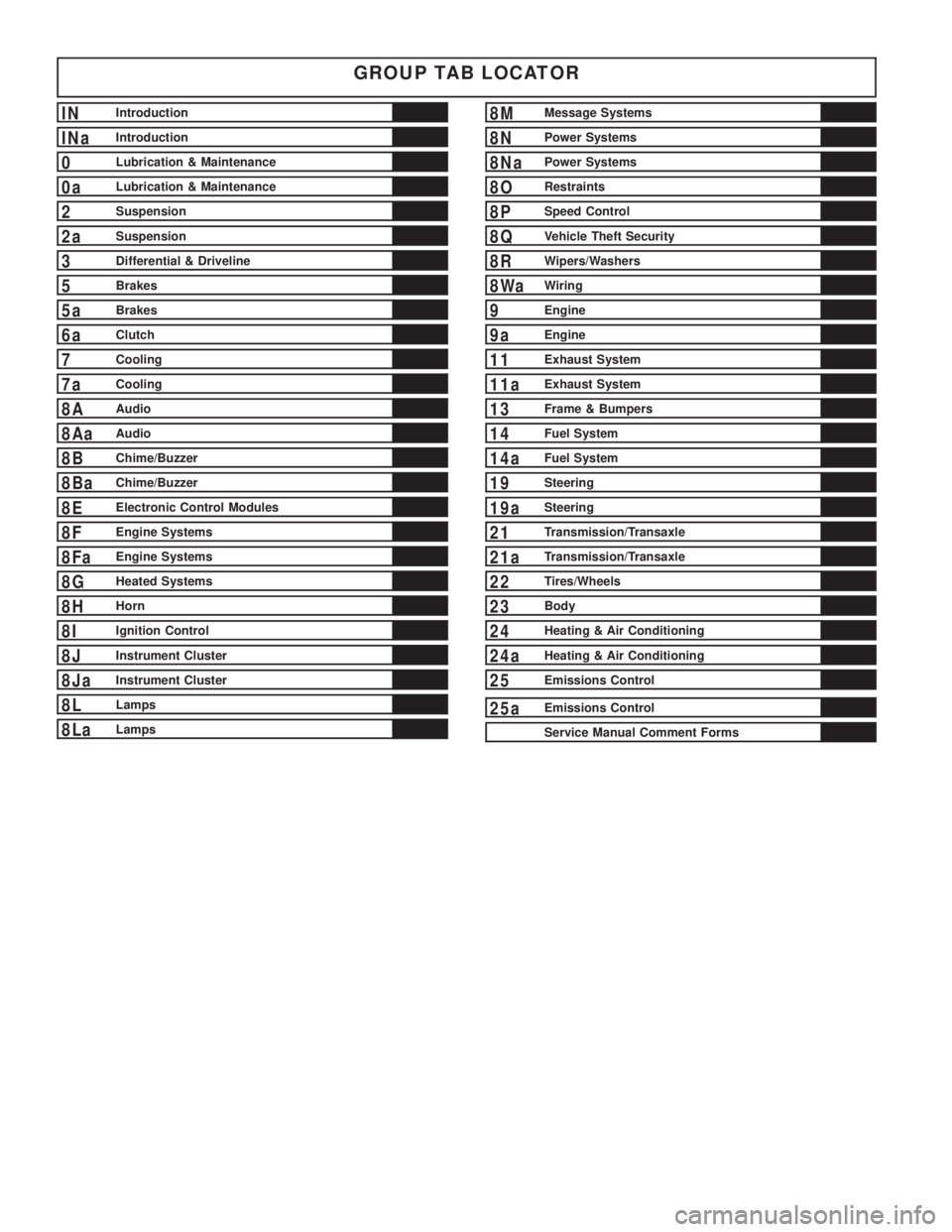
GROUP TAB LOCATOR
INIntroduction
INaIntroduction
0Lubrication & Maintenance
0aLubrication & Maintenance
2Suspension
2aSuspension
3Differential & Driveline
5Brakes
5aBrakes
6aClutch
7Cooling
7aCooling
8AAudio
8AaAudio
8BChime/Buzzer
8BaChime/Buzzer
8EElectronic Control Modules
8FEngine Systems
8FaEngine Systems
8GHeated Systems
8HHorn
8IIgnition Control
8JInstrument Cluster
8JaInstrument Cluster
8LLamps
8LaLamps
8MMessage Systems
8NPower Systems
8NaPower Systems
8ORestraints
8PSpeed Control
8QVehicle Theft Security
8RWipers/Washers
8WaWiring
9Engine
9aEngine
11Exhaust System
11aExhaust System
13Frame & Bumpers
14Fuel System
14aFuel System
19Steering
19aSteering
21Transmission/Transaxle
21aTransmission/Transaxle
22Tires/Wheels
23Body
24Heating & Air Conditioning
24aHeating & Air Conditioning
25Emissions Control
25aEmissions Control
Service Manual Comment Forms
Page 1489 of 4284
LUBRICATION & MAINTENANCE
TABLE OF CONTENTS
page page
LUBRICATION & MAINTENANCE
SPECIFICATIONS.........................1
INTERNATIONAL SYMBOLS
DESCRIPTION............................1
PARTS & LUBRICANT RECOMMENDATION
STANDARD PROCEDURE...................2
LUBRICANT CLASSIFICATIONS.............2
PARTS AND LUBRICANT
RECOMMENDATIONS....................2
FLUID TYPES
DESCRIPTION............................3
OPERATION.............................7
FLUID FILL/CHECK LOCATIONS
DESCRIPTION............................7MAINTENANCE SCHEDULES
DESCRIPTION............................7
HOISTING
STANDARD PROCEDURE..................16
HOISTING............................16
JUMP STARTING
STANDARD PROCEDURE..................16
JUMP STARTING.......................16
TOWING
STANDARD PROCEDURE..................17
TOWING RECOMMENDATIONS............17
LUBRICATION &
MAINTENANCE
SPECIFICATIONS
SPECIFICATIONS - FLUID CAPACITIES
DESCRIPTION SPECIFICATION
Fuel Tank 75 L (20 gal.)
Engine Oil* - 2.4L 4.7 L (5.0 qts.)
Engine Oil* - 3.3/3.8L 4.0 L (4.5 qts.)
Cooling System** - 2.4L 10.7 L (11.4 qts.)
Cooling System** -
3.3/3.8L without Rear
Heater12.6 L (13.4 qts.)
Cooling System** -
3.3/3.8L with Rear Heater15.4 L (16.3 qts.)
Automatic Transaxle -
Service Fill3.8 L (4.0 qts.)
Automatic Transaxle -
31TH Overhaul Fill8.6 L (9.1 qts.)
Automatic Transaxle -
41TE Overhaul Fill9.2 L (9.7 qts.)
AWD Power Transfer Unit 1.15 L (2.4 pts.)
Power Steering 1.2 L (2.5 pts.)
AWD Bi-directional
Overrunning Clutch0.575 L (1.22 pts.)
DESCRIPTION SPECIFICATION
AWD Rear Carrier 0.7 L (1.48 pts.)
*(includes oil filter)
**(includes heater and recovery/reserve bottle)
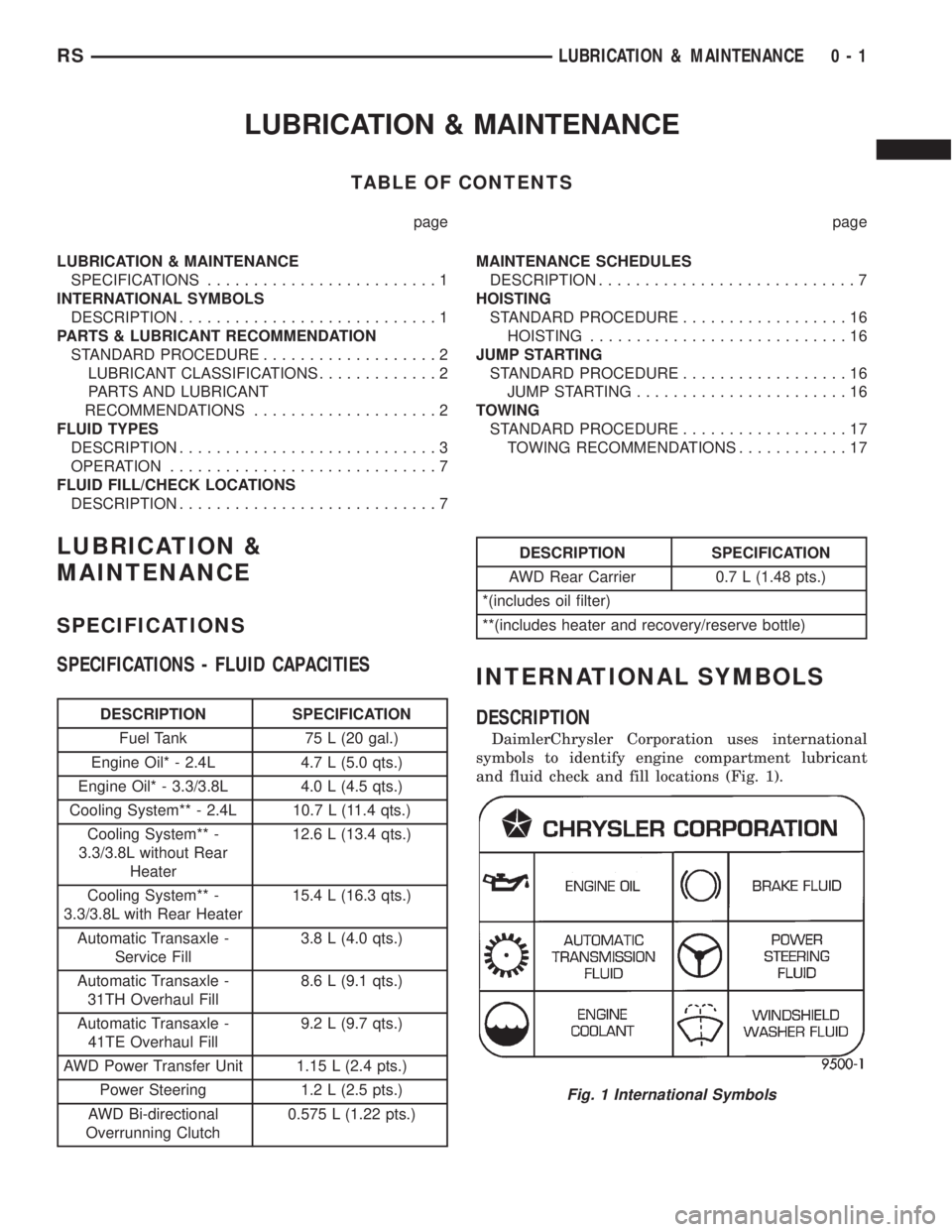
INTERNATIONAL SYMBOLS
DESCRIPTION
DaimlerChrysler Corporation uses international
symbols to identify engine compartment lubricant
and fluid check and fill locations (Fig. 1).
Fig. 1 International Symbols
RSLUBRICATION & MAINTENANCE0-1
Page 1494 of 4284
NOTE: Intentional tampering with emissions control
systems can result in civil penalties being assessed
against you.
GEAR LUBRICATION ± RATINGS
SAE ratings also apply to multiple grade gear
lubricants. In addition, API classification defines the
lubricants usage.
DESCRIPTION - ENGINE COOLANT
WARNING: ANTIFREEZE IS AN ETHYLENE GLYCOL
BASE COOLANT AND IS HARMFUL IF SWAL-
LOWED OR INHALED. IF SWALLOWED, DRINK
TWO GLASSES OF WATER AND INDUCE VOMIT-
ING. IF INHALED, MOVE TO FRESH AIR AREA.
SEEK MEDICAL ATTENTION IMMEDIATELY. DO NOT
STORE IN OPEN OR UNMARKED CONTAINERS.
WASH SKIN AND CLOTHING THOROUGHLY AFTER
COMING IN CONTACT WITH ETHYLENE GLYCOL.
KEEP OUT OF REACH OF CHILDREN. DISPOSE OF
GLYCOL BASE COOLANT PROPERLY, CONTACT
YOUR DEALER OR GOVERNMENT AGENCY FOR
LOCATION OF COLLECTION CENTER IN YOUR
AREA. DO NOT OPEN A COOLING SYSTEM WHEN
THE ENGINE IS AT OPERATING TEMPERATURE OR
HOT UNDER PRESSURE, PERSONAL INJURY CAN
RESULT. AVOID RADIATOR COOLING FAN WHEN
ENGINE COMPARTMENT RELATED SERVICE IS
PERFORMED, PERSONAL INJURY CAN RESULT.
CAUTION: Use of Propylene Glycol based coolants
is not recommended, as they provide less freeze
protection and less corrosion protection.
The cooling system is designed around the coolant.
The coolant must accept heat from engine metal, in
the cylinder head area near the exhaust valves and
engine block. Then coolant carries the heat to the
radiator where the tube/fin radiator can transfer the
heat to the air.
The use of aluminum cylinder blocks, cylinder
heads, and water pumps requires special corrosion
protection. MopartAntifreeze/Coolant, 5 Year/
100,000 Mile Formula (MS-9769), or the equivalent
ethylene glycol base coolant with organic corrosion
inhibitors (called HOAT, for Hybrid Organic Additive
Technology) is recommended. This coolant offers the
best engine cooling without corrosion when mixed
with 50% Ethylene Glycol and 50% distilled water to
obtain a freeze point of -37ÉC (-35ÉF). If it loses color
or becomes contaminated, drain, flush, and replace
with fresh properly mixed coolant solution.CAUTION: MoparTAntifreeze/Coolant, 5 Year/
100,000 Mile Formula (MS-9769) may not be mixed
with any other type of antifreeze. Doing so will
reduce the corrosion protection and may result in
premature water pump seal failure. If non-HOAT
coolant is introduced into the cooling system in an
emergency, it should be replaced with the specified
coolant as soon as possible.
DESCRIPTION - LUBRICANTS AND GREASES
When service is required, DaimlerChrysler Corpo-
ration recommends that only Mopartbrand parts,
lubricants and chemicals be used. Mopartprovides
the best engineered products for servicing
DaimlerChrysler Corporation vehicles.
Only lubricants bearing designations defined by
the following organization should be used to service a
Chrysler Corporation vehicle.
²Society of Automotive Engineers (SAE)
²American Petroleum Institute (API) (Fig. 6)
²National Lubricating Grease Institute (NLGI)
(Fig. 7)
SAE VISCOSITY RATING
An SAE viscosity grade is used to specify the vis-
cosity of engine oil. These are specified with a dual
SAE viscosity grade which indicates the cold-to-hot
temperature viscosity range. Example SAE 5W-30 =
multiple grade engine oil.
DaimlerChrysler Corporation only recommends
multiple grade engine oils.
API QUALITY CLASSIFICATION
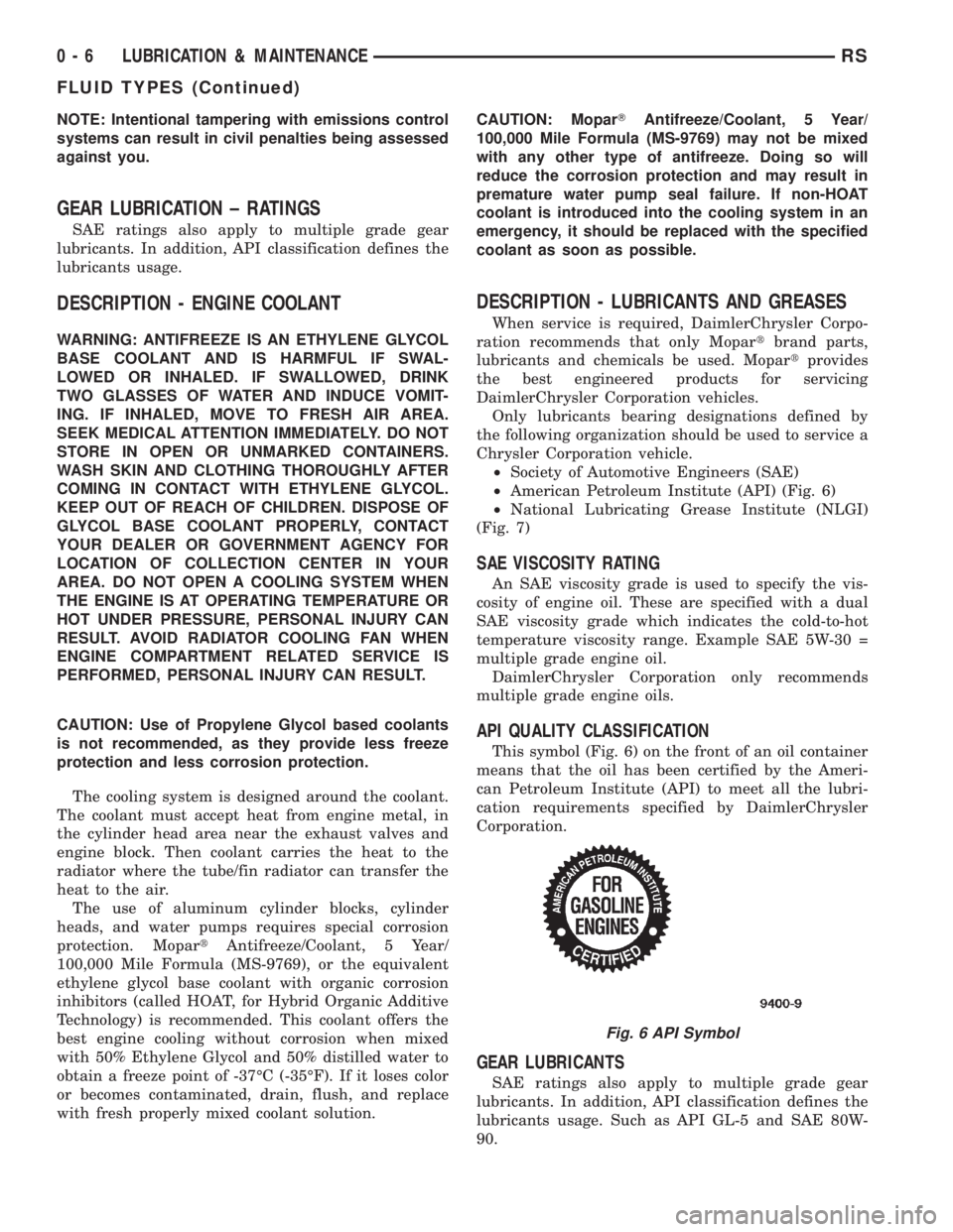
This symbol (Fig. 6) on the front of an oil container
means that the oil has been certified by the Ameri-
can Petroleum Institute (API) to meet all the lubri-
cation requirements specified by DaimlerChrysler
Corporation.
GEAR LUBRICANTS
SAE ratings also apply to multiple grade gear
lubricants. In addition, API classification defines the
lubricants usage. Such as API GL-5 and SAE 80W-
90.
Fig. 6 API Symbol
0 - 6 LUBRICATION & MAINTENANCERS
FLUID TYPES (Continued)