2001 CHRYSLER VOYAGER frame
[x] Cancel search: framePage 1224 of 4284
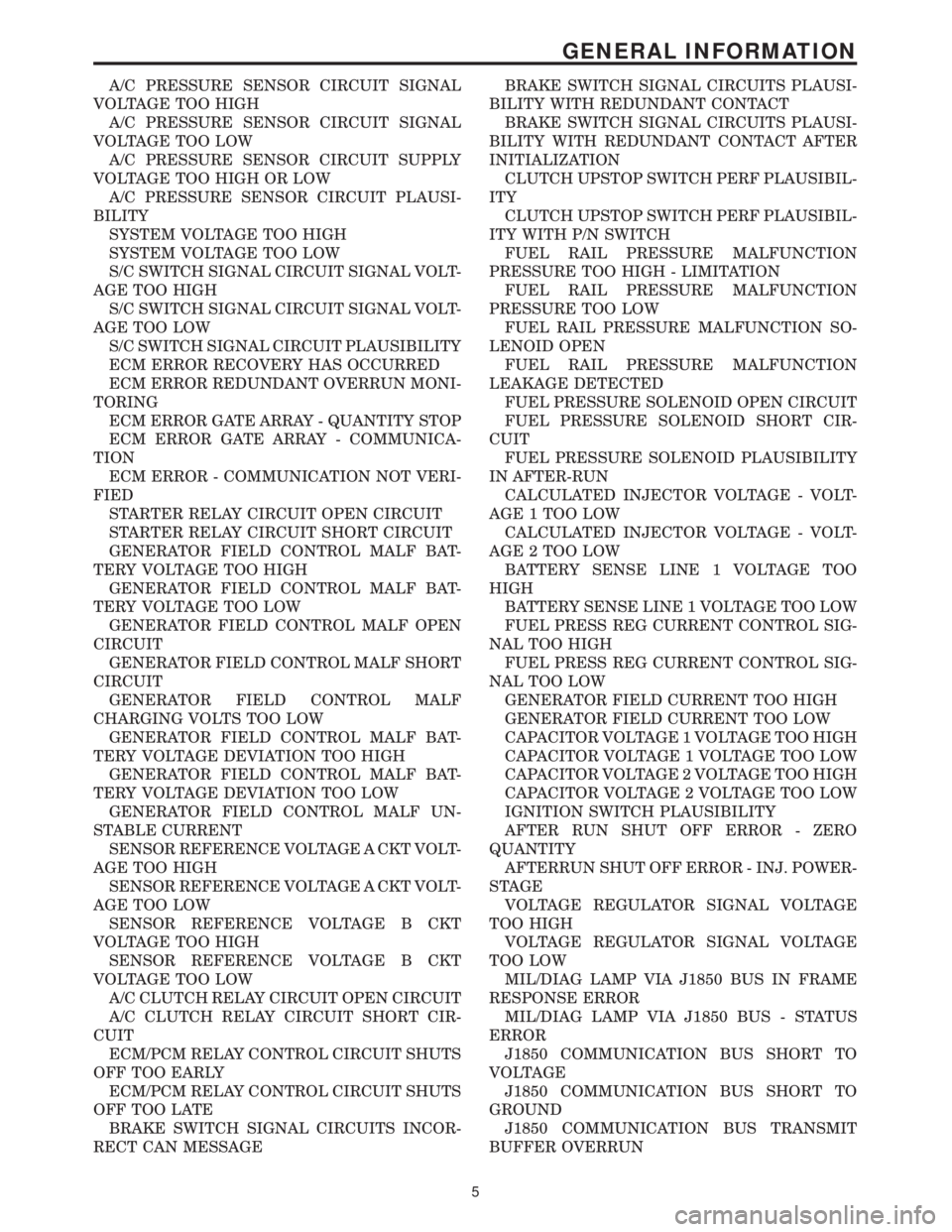
A/C PRESSURE SENSOR CIRCUIT SIGNAL
VOLTAGE TOO HIGH
A/C PRESSURE SENSOR CIRCUIT SIGNAL
VOLTAGE TOO LOW
A/C PRESSURE SENSOR CIRCUIT SUPPLY
VOLTAGE TOO HIGH OR LOW
A/C PRESSURE SENSOR CIRCUIT PLAUSI-
BILITY
SYSTEM VOLTAGE TOO HIGH
SYSTEM VOLTAGE TOO LOW
S/C SWITCH SIGNAL CIRCUIT SIGNAL VOLT-
AGE TOO HIGH
S/C SWITCH SIGNAL CIRCUIT SIGNAL VOLT-
AGE TOO LOW
S/C SWITCH SIGNAL CIRCUIT PLAUSIBILITY
ECM ERROR RECOVERY HAS OCCURRED
ECM ERROR REDUNDANT OVERRUN MONI-
TORING
ECM ERROR GATE ARRAY - QUANTITY STOP
ECM ERROR GATE ARRAY - COMMUNICA-
TION
ECM ERROR - COMMUNICATION NOT VERI-
FIED
STARTER RELAY CIRCUIT OPEN CIRCUIT
STARTER RELAY CIRCUIT SHORT CIRCUIT
GENERATOR FIELD CONTROL MALF BAT-
TERY VOLTAGE TOO HIGH
GENERATOR FIELD CONTROL MALF BAT-
TERY VOLTAGE TOO LOW
GENERATOR FIELD CONTROL MALF OPEN
CIRCUIT
GENERATOR FIELD CONTROL MALF SHORT
CIRCUIT
GENERATOR FIELD CONTROL MALF
CHARGING VOLTS TOO LOW
GENERATOR FIELD CONTROL MALF BAT-
TERY VOLTAGE DEVIATION TOO HIGH
GENERATOR FIELD CONTROL MALF BAT-
TERY VOLTAGE DEVIATION TOO LOW
GENERATOR FIELD CONTROL MALF UN-
STABLE CURRENT
SENSOR REFERENCE VOLTAGE A CKT VOLT-
AGE TOO HIGH
SENSOR REFERENCE VOLTAGE A CKT VOLT-
AGE TOO LOW
SENSOR REFERENCE VOLTAGE B CKT
VOLTAGE TOO HIGH
SENSOR REFERENCE VOLTAGE B CKT
VOLTAGE TOO LOW
A/C CLUTCH RELAY CIRCUIT OPEN CIRCUIT
A/C CLUTCH RELAY CIRCUIT SHORT CIR-
CUIT
ECM/PCM RELAY CONTROL CIRCUIT SHUTS
OFF TOO EARLY
ECM/PCM RELAY CONTROL CIRCUIT SHUTS
OFF TOO LATE
BRAKE SWITCH SIGNAL CIRCUITS INCOR-
RECT CAN MESSAGEBRAKE SWITCH SIGNAL CIRCUITS PLAUSI-
BILITY WITH REDUNDANT CONTACT
BRAKE SWITCH SIGNAL CIRCUITS PLAUSI-
BILITY WITH REDUNDANT CONTACT AFTER
INITIALIZATION
CLUTCH UPSTOP SWITCH PERF PLAUSIBIL-
ITY
CLUTCH UPSTOP SWITCH PERF PLAUSIBIL-
ITY WITH P/N SWITCH
FUEL RAIL PRESSURE MALFUNCTION
PRESSURE TOO HIGH - LIMITATION
FUEL RAIL PRESSURE MALFUNCTION
PRESSURE TOO LOW
FUEL RAIL PRESSURE MALFUNCTION SO-
LENOID OPEN
FUEL RAIL PRESSURE MALFUNCTION
LEAKAGE DETECTED
FUEL PRESSURE SOLENOID OPEN CIRCUIT
FUEL PRESSURE SOLENOID SHORT CIR-
CUIT
FUEL PRESSURE SOLENOID PLAUSIBILITY
IN AFTER-RUN
CALCULATED INJECTOR VOLTAGE - VOLT-
AGE 1 TOO LOW
CALCULATED INJECTOR VOLTAGE - VOLT-
AGE 2 TOO LOW
BATTERY SENSE LINE 1 VOLTAGE TOO
HIGH
BATTERY SENSE LINE 1 VOLTAGE TOO LOW
FUEL PRESS REG CURRENT CONTROL SIG-
NAL TOO HIGH
FUEL PRESS REG CURRENT CONTROL SIG-
NAL TOO LOW
GENERATOR FIELD CURRENT TOO HIGH
GENERATOR FIELD CURRENT TOO LOW
CAPACITOR VOLTAGE 1 VOLTAGE TOO HIGH
CAPACITOR VOLTAGE 1 VOLTAGE TOO LOW
CAPACITOR VOLTAGE 2 VOLTAGE TOO HIGH
CAPACITOR VOLTAGE 2 VOLTAGE TOO LOW
IGNITION SWITCH PLAUSIBILITY
AFTER RUN SHUT OFF ERROR - ZERO
QUANTITY
AFTERRUN SHUT OFF ERROR - INJ. POWER-
STAGE
VOLTAGE REGULATOR SIGNAL VOLTAGE
TOO HIGH
VOLTAGE REGULATOR SIGNAL VOLTAGE
TOO LOW
MIL/DIAG LAMP VIA J1850 BUS IN FRAME
RESPONSE ERROR
MIL/DIAG LAMP VIA J1850 BUS - STATUS
ERROR
J1850 COMMUNICATION BUS SHORT TO
VOLTAGE
J1850 COMMUNICATION BUS SHORT TO
GROUND
J1850 COMMUNICATION BUS TRANSMIT
BUFFER OVERRUN
5
GENERAL INFORMATION
Page 1359 of 4284
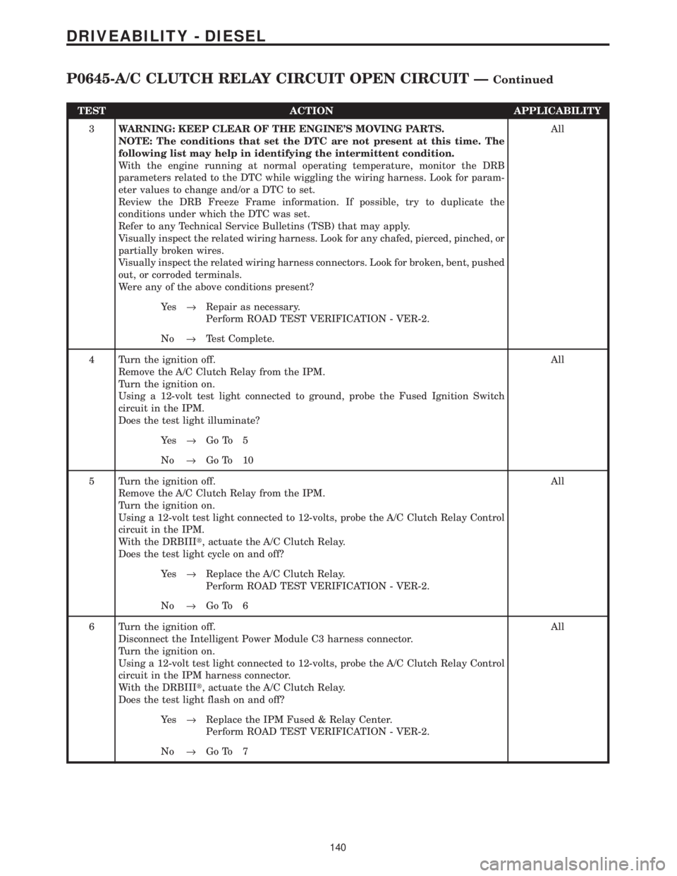
TEST ACTION APPLICABILITY
3WARNING: KEEP CLEAR OF THE ENGINE'S MOVING PARTS.
NOTE: The conditions that set the DTC are not present at this time. The
following list may help in identifying the intermittent condition.
With the engine running at normal operating temperature, monitor the DRB
parameters related to the DTC while wiggling the wiring harness. Look for param-
eter values to change and/or a DTC to set.
Review the DRB Freeze Frame information. If possible, try to duplicate the
conditions under which the DTC was set.
Refer to any Technical Service Bulletins (TSB) that may apply.
Visually inspect the related wiring harness. Look for any chafed, pierced, pinched, or
partially broken wires.
Visually inspect the related wiring harness connectors. Look for broken, bent, pushed
out, or corroded terminals.
Were any of the above conditions present?All
Ye s®Repair as necessary.
Perform ROAD TEST VERIFICATION - VER-2.
No®Test Complete.
4 Turn the ignition off.
Remove the A/C Clutch Relay from the IPM.
Turn the ignition on.
Using a 12-volt test light connected to ground, probe the Fused Ignition Switch
circuit in the IPM.
Does the test light illuminate?All
Ye s®Go To 5
No®Go To 10
5 Turn the ignition off.
Remove the A/C Clutch Relay from the IPM.
Turn the ignition on.
Using a 12-volt test light connected to 12-volts, probe the A/C Clutch Relay Control
circuit in the IPM.
With the DRBIIIt, actuate the A/C Clutch Relay.
Does the test light cycle on and off?All
Ye s®Replace the A/C Clutch Relay.
Perform ROAD TEST VERIFICATION - VER-2.
No®Go To 6
6 Turn the ignition off.
Disconnect the Intelligent Power Module C3 harness connector.
Turn the ignition on.
Using a 12-volt test light connected to 12-volts, probe the A/C Clutch Relay Control
circuit in the IPM harness connector.
With the DRBIIIt, actuate the A/C Clutch Relay.
Does the test light flash on and off?All
Ye s®Replace the IPM Fused & Relay Center.
Perform ROAD TEST VERIFICATION - VER-2.
No®Go To 7
140
DRIVEABILITY - DIESEL
P0645-A/C CLUTCH RELAY CIRCUIT OPEN CIRCUIT ÐContinued
Page 1362 of 4284
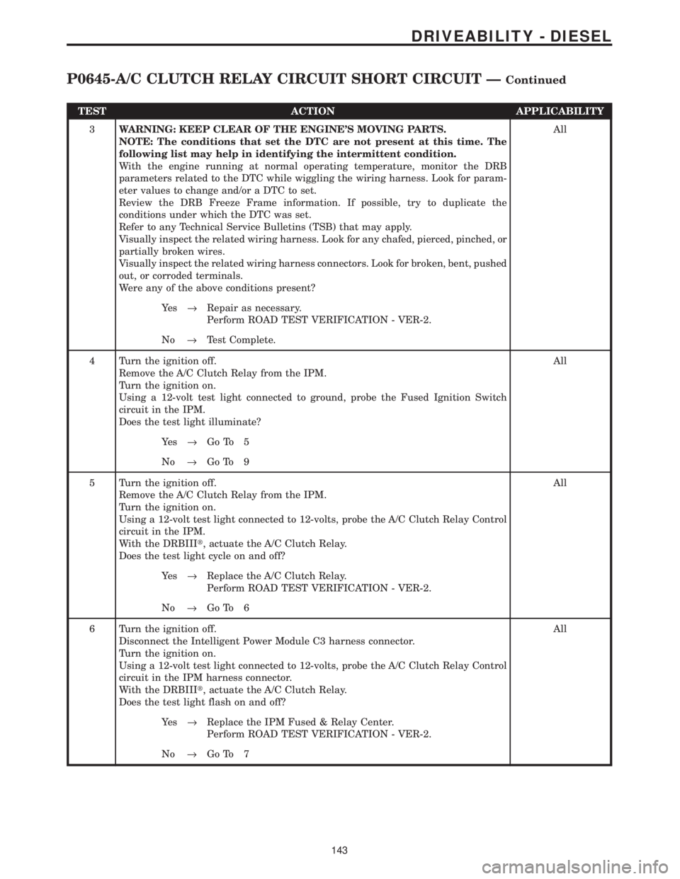
TEST ACTION APPLICABILITY
3WARNING: KEEP CLEAR OF THE ENGINE'S MOVING PARTS.
NOTE: The conditions that set the DTC are not present at this time. The
following list may help in identifying the intermittent condition.
With the engine running at normal operating temperature, monitor the DRB
parameters related to the DTC while wiggling the wiring harness. Look for param-
eter values to change and/or a DTC to set.
Review the DRB Freeze Frame information. If possible, try to duplicate the
conditions under which the DTC was set.
Refer to any Technical Service Bulletins (TSB) that may apply.
Visually inspect the related wiring harness. Look for any chafed, pierced, pinched, or
partially broken wires.
Visually inspect the related wiring harness connectors. Look for broken, bent, pushed
out, or corroded terminals.
Were any of the above conditions present?All
Ye s®Repair as necessary.
Perform ROAD TEST VERIFICATION - VER-2.
No®Test Complete.
4 Turn the ignition off.
Remove the A/C Clutch Relay from the IPM.
Turn the ignition on.
Using a 12-volt test light connected to ground, probe the Fused Ignition Switch
circuit in the IPM.
Does the test light illuminate?All
Ye s®Go To 5
No®Go To 9
5 Turn the ignition off.
Remove the A/C Clutch Relay from the IPM.
Turn the ignition on.
Using a 12-volt test light connected to 12-volts, probe the A/C Clutch Relay Control
circuit in the IPM.
With the DRBIIIt, actuate the A/C Clutch Relay.
Does the test light cycle on and off?All
Ye s®Replace the A/C Clutch Relay.
Perform ROAD TEST VERIFICATION - VER-2.
No®Go To 6
6 Turn the ignition off.
Disconnect the Intelligent Power Module C3 harness connector.
Turn the ignition on.
Using a 12-volt test light connected to 12-volts, probe the A/C Clutch Relay Control
circuit in the IPM harness connector.
With the DRBIIIt, actuate the A/C Clutch Relay.
Does the test light flash on and off?All
Ye s®Replace the IPM Fused & Relay Center.
Perform ROAD TEST VERIFICATION - VER-2.
No®Go To 7
143
DRIVEABILITY - DIESEL
P0645-A/C CLUTCH RELAY CIRCUIT SHORT CIRCUIT ÐContinued
Page 1468 of 4284
GROUP TAB LOCATOR
INIntroduction
INaIntroduction
0Lubrication & Maintenance
0aLubrication & Maintenance
2Suspension
2aSuspension
3Differential & Driveline
5Brakes
5aBrakes
6aClutch
7Cooling
7aCooling
8AAudio
8AaAudio
8BChime/Buzzer
8BaChime/Buzzer
8EElectronic Control Modules
8FEngine Systems
8FaEngine Systems
8GHeated Systems
8HHorn
8IIgnition Control
8JInstrument Cluster
8JaInstrument Cluster
8LLamps
8LaLamps
8MMessage Systems
8NPower Systems
8NaPower Systems
8ORestraints
8PSpeed Control
8QVehicle Theft Security
8RWipers/Washers
8WaWiring
9Engine
9aEngine
11Exhaust System
11aExhaust System
13Frame & Bumpers
14Fuel System
14aFuel System
19Steering
19aSteering
21Transmission/Transaxle
21aTransmission/Transaxle
22Tires/Wheels
23Body
24Heating & Air Conditioning
24aHeating & Air Conditioning
25Emissions Control
25aEmissions Control
Service Manual Comment Forms
Page 1504 of 4284
Inspection and service should also be performed
anytime a malfunction is observed or suspected.
HOISTING
STANDARD PROCEDURE - HOISTING
Refer to Owner's Manual provided with vehicle for
proper emergency jacking procedures.
WARNING: THE HOISTING AND JACK LIFTING
POINTS PROVIDED ARE FOR A COMPLETE VEHI-
CLE. WHEN THE ENGINE OR REAR SUSPENSION
IS REMOVED FROM A VEHICLE, THE CENTER OF
GRAVITY IS ALTERED MAKING SOME HOISTING
CONDITIONS UNSTABLE. PROPERLY SUPPORT OR
SECURE VEHICLE TO HOISTING DEVICE WHEN
THESE CONDITIONS EXIST.
CAUTION: Do not position hoisting device on any
suspension component, including the front suspen-
sion crossmember, the rear leaf springs, and the
rear axle. Do not hoist on the front and rear
bumpers, the lower liftgate crossmember, the lower
radiator crossmember, the down standing flanges
on the sill or the front engine mount.
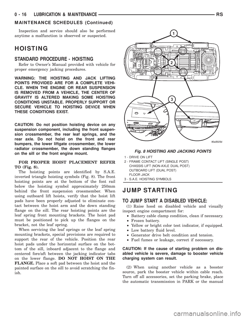
FOR PROPER HOIST PLACEMENT REFER
TO (Fig. 8).
The hoisting points are identified by S.A.E.
inverted triangle hoisting symbols (Fig. 8). The front
hoisting points are at the bottom of the font rail
below the hoisting symbol approximately 250mm
behind the front suspension crossmember. When
using outboard lift hoists, verify that the hoist lift
pads have been properly adjusted to eliminate con-
tact between the hoist arm and the down standing
flange on the sill. The rear hoisting points are the
leaf spring front mounting brackets. The hoist pad
must be positioned to pick up the flanges on the
bracket, not the leaf spring.
When servicing the leaf springs or the leaf spring
mounting brackets, special provisions are required to
support the rear of the vehicle. Position the rear
hoist pads under the horizontal surface on the bot-
tom of the sill, inboard adjacent to the flange and
centered fore/aft between the jacking indicator tabs
on the lower flange.DO NOT HOIST ON THE
FLANGE.Place a soft pad between the hoist and the
painted surface on the sill to avoid scratching the fin-
ish.
JUMP STARTING
TO JUMP START A DISABLED VEHICLE:
(1) Raise hood on disabled vehicle and visually
inspect engine compartment for:
²Battery cable clamp condition, clean if necessary.
²Frozen battery.
²Yellow or bright color test indicator, if equipped.
²Low battery fluid level.
²Generator drive belt condition and tension.
²Fuel fumes or leakage, correct if necessary.
CAUTION: If the cause of starting problem on dis-
abled vehicle is severe, damage to booster vehicle
charging system can result.
(2) When using another vehicle as a booster
source, park the booster vehicle within cable reach.
Turn off all accessories, set the parking brake, place
the automatic transmission in PARK or the manual
Fig. 8 HOISTING AND JACKING POINTS
1 - DRIVE ON LIFT
2 - FRAME CONTACT LIFT (SINGLE POST)
CHASSIS LIFT (NON-AXLE DUAL POST)
OUTBOARD LIFT (DUAL POST)
FLOOR JACK
3 - S.A.E. HOISTING SYMBOLS
0 - 16 LUBRICATION & MAINTENANCERS
MAINTENANCE SCHEDULES (Continued)
Page 1513 of 4284
²Inspect air filter element.
²Replace fuel filter/water separator element. (2)
²Check alignment.
140 000 km (86 000 Miles)
²Change engine oil. (1)
²Replace engine oil filter.
²Replace air filter element.
150 000 km (93 000 Miles)
²Change engine oil. (1)
²Replace engine oil filter.
²Inspect air filter element.
²Replace fuel filter/water separator element. (2)
²Check alignment.
160 000 km (100 000 Miles)
²Change engine oil. (1)
²Replace engine oil filter.
²Replace air filter element.
²Flush and replace engine coolant. (3)
²Change oil every 12 months regardless of mile-
age.
²The fuel filter/water separator element should
be replaced once a year if the vehicle is driven less
than 20 000 km annually or if power loss from fuel
starvation is detected.
²
Flush and replace engine coolant every 60 months
even if the vehicle is driven less than 160 000 km.
²Change manual transaxle fluid.
HOISTING
STANDARD PROCEDURE - HOISTING
Refer to Owner's Manual provided with vehicle for
proper emergency jacking procedures.
WARNING: THE HOISTING AND JACK LIFTING
POINTS PROVIDED ARE FOR A COMPLETE VEHI-
CLE. WHEN THE ENGINE OR REAR SUSPENSION
IS REMOVED FROM A VEHICLE, THE CENTER OF
GRAVITY IS ALTERED MAKING SOME HOISTING
CONDITIONS UNSTABLE. PROPERLY SUPPORT OR
SECURE VEHICLE TO HOISTING DEVICE WHEN
THESE CONDITIONS EXIST.
CAUTION: Do not position hoisting device on any
suspension component, including the front suspen-
sion crossmember, the rear leaf springs, and the
rear axle. Do not hoist on the front and rear
bumpers, the lower liftgate crossmember, the lower
radiator crossmember, the down standing flanges
on the sill or the front engine mount.
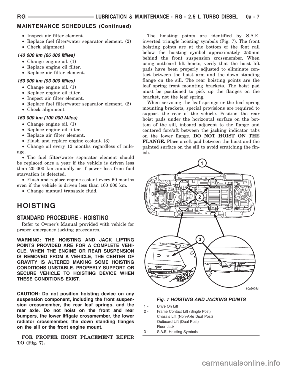
FOR PROPER HOIST PLACEMENT REFER
TO (Fig. 7).The hoisting points are identified by S.A.E.
inverted triangle hoisting symbols (Fig. 7). The front
hoisting points are at the bottom of the font rail
below the hoisting symbol approximately 250mm
behind the front suspension crossmember. When
using outboard lift hoists, verify that the hoist lift
pads have been properly adjusted to eliminate con-
tact between the hoist arm and the down standing
flange on the sill. The rear hoisting points are the
leaf spring front mounting brackets. The hoist pad
must be positioned to pick up the flanges on the
bracket, not the leaf spring.
When servicing the leaf springs or the leaf spring
mounting brackets, special provisions are required to
support the rear of the vehicle. Position the rear
hoist pads under the horizontal surface on the bot-
tom of the sill, inboard adjacent to the flange and
centered fore/aft between the jacking indicator tabs
on the lower flange.DO NOT HOIST ON THE
FLANGE.Place a soft pad between the hoist and the
painted surface on the sill to avoid scratching the fin-
ish.
Fig. 7 HOISTING AND JACKING POINTS
1 - Drive On Lift
2 - Frame Contact Lift (Single Post)
Chassis Lift (Non-Axle Dual Post)
Outboard Lift (Dual Post)
Floor Jack
3 - S.A.E. Hoisting Symbols
RGLUBRICATION & MAINTENANCE - RG - 2.5 L TURBO DIESEL0a-7
MAINTENANCE SCHEDULES (Continued)
Page 1521 of 4284
DIAGNOSIS AND TESTING - HUB AND
BEARING (FRONT)
The condition of the front hub and bearing assem-
bly is diagnosed using the inspection and testing pro-
cedure detailed below.
The bearing contained in the Unit III front hub/
bearing assembly will produce noise and vibration
when worn or damaged. The noise will generally
change when the bearings are loaded. A road test of
the vehicle is normally required to determine the
location of a worn or damaged bearing.
Find a smooth level road surface and bring the
vehicle up to a constant speed. When vehicle is at a
constant speed, swerve the vehicle back and forth
from the left and to the right. This will load and
unload the bearings and change the noise level.
Where axle bearing damage is slight, the noise is
usually not noticeable at speeds above 48 km/h (30
mph).
REMOVAL - HUB AND BEARING
NOTE: Replacement of the Unit III front hub/bearing
assembly can be normally done without having to
remove the steering knuckle from the vehicle. In the
event that the hub/bearing is frozen in the steering
knuckle and cannot be removed by hand, it will
have to be pressed out of the steering knuckle. The
steering knuckle will require removal from the vehi-
cle to allow the hub/bearing assembly to be
pressed out of the steering knuckle. (Refer to 2 -
SUSPENSION/FRONT/KNUCKLE - REMOVAL)
(1) Raise vehicle on jack stands or centered on a
frame contact type hoist. See Hoisting in Lubrication
and Maintenance.
(2) Remove wheel lug nuts, and front tire and
wheel assembly.
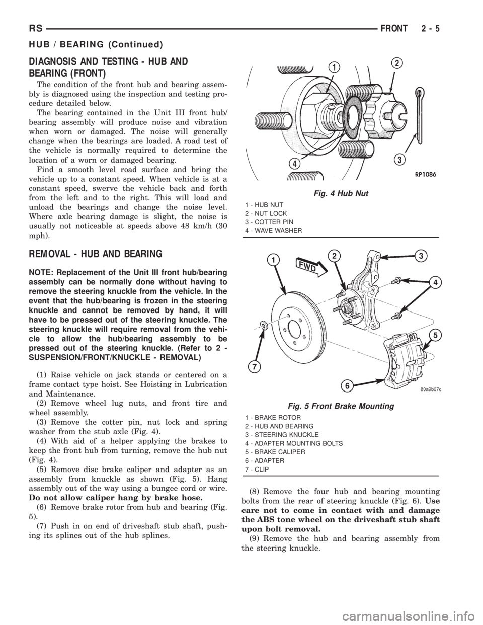
(3) Remove the cotter pin, nut lock and spring
washer from the stub axle (Fig. 4).
(4) With aid of a helper applying the brakes to
keep the front hub from turning, remove the hub nut
(Fig. 4).
(5) Remove disc brake caliper and adapter as an
assembly from knuckle as shown (Fig. 5). Hang
assembly out of the way using a bungee cord or wire.
Do not allow caliper hang by brake hose.
(6) Remove brake rotor from hub and bearing (Fig.
5).
(7) Push in on end of driveshaft stub shaft, push-
ing its splines out of the hub splines.(8) Remove the four hub and bearing mounting
bolts from the rear of steering knuckle (Fig. 6).Use
care not to come in contact with and damage
the ABS tone wheel on the driveshaft stub shaft
upon bolt removal.
(9) Remove the hub and bearing assembly from
the steering knuckle.
Fig. 4 Hub Nut
1 - HUB NUT
2 - NUT LOCK
3 - COTTER PIN
4 - WAVE WASHER
Fig. 5 Front Brake Mounting
1 - BRAKE ROTOR
2 - HUB AND BEARING
3 - STEERING KNUCKLE
4 - ADAPTER MOUNTING BOLTS
5 - BRAKE CALIPER
6 - ADAPTER
7 - CLIP
RSFRONT2-5
HUB / BEARING (Continued)
Page 1523 of 4284
REMOVAL - STEERING KNUCKLE
(1) Raise vehicle on jack stands or centered on a
frame contact type hoist. Refer to Hoisting in Lubri-
cation And Maintenance.
(2) Remove the wheel and tire assembly from the
vehicle.
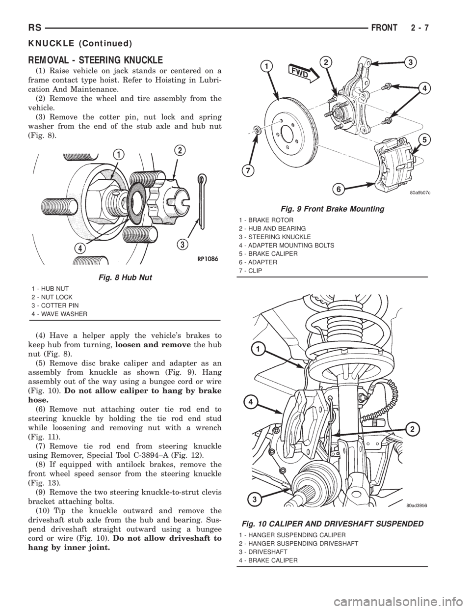
(3) Remove the cotter pin, nut lock and spring
washer from the end of the stub axle and hub nut
(Fig. 8).
(4) Have a helper apply the vehicle's brakes to
keep hub from turning,loosen and removethe hub
nut (Fig. 8).
(5) Remove disc brake caliper and adapter as an
assembly from knuckle as shown (Fig. 9). Hang
assembly out of the way using a bungee cord or wire
(Fig. 10).Do not allow caliper to hang by brake
hose.
(6) Remove nut attaching outer tie rod end to
steering knuckle by holding the tie rod end stud
while loosening and removing nut with a wrench
(Fig. 11).
(7) Remove tie rod end from steering knuckle
using Remover, Special Tool C-3894±A (Fig. 12).
(8) If equipped with antilock brakes, remove the
front wheel speed sensor from the steering knuckle
(Fig. 13).
(9) Remove the two steering knuckle-to-strut clevis
bracket attaching bolts.
(10) Tip the knuckle outward and remove the
driveshaft stub axle from the hub and bearing. Sus-
pend driveshaft straight outward using a bungee
cord or wire (Fig. 10).Do not allow driveshaft to
hang by inner joint.
Fig. 8 Hub Nut
1 - HUB NUT
2 - NUT LOCK
3 - COTTER PIN
4 - WAVE WASHER
Fig. 9 Front Brake Mounting
1 - BRAKE ROTOR
2 - HUB AND BEARING
3 - STEERING KNUCKLE
4 - ADAPTER MOUNTING BOLTS
5 - BRAKE CALIPER
6 - ADAPTER
7 - CLIP
Fig. 10 CALIPER AND DRIVESHAFT SUSPENDED
1 - HANGER SUSPENDING CALIPER
2 - HANGER SUSPENDING DRIVESHAFT
3 - DRIVESHAFT
4 - BRAKE CALIPER
RSFRONT2-7
KNUCKLE (Continued)