2001 CHRYSLER VOYAGER frame
[x] Cancel search: framePage 1738 of 4284
- 124 kPa (14 - 18 psi). This air is replaced with cool-
ant from the coolant bottle.
NOTE: Deaeration does not occur at engine idleÐ
higher engine speeds are required. Normal driving
will deaerate cooling system.
To effectively deaerate the system, multiple ther-
mal cycles of the system may be required.
STANDARD PROCEDURE - COOLING SYSTEM
DRAINING
WARNING: DO NOT REMOVE OR LOOSEN THE
COOLANT PRESSURE CAP, CYLINDER BLOCK
DRAIN PLUGS, OR THE DRAINCOCK WHEN THE
SYSTEM IS HOT AND UNDER PRESSURE
BECAUSE SERIOUS BURNS FROM THE COOLANT
CAN OCCUR.
(1)Without removing radiator pressure cap
and with system not under pressure, open the
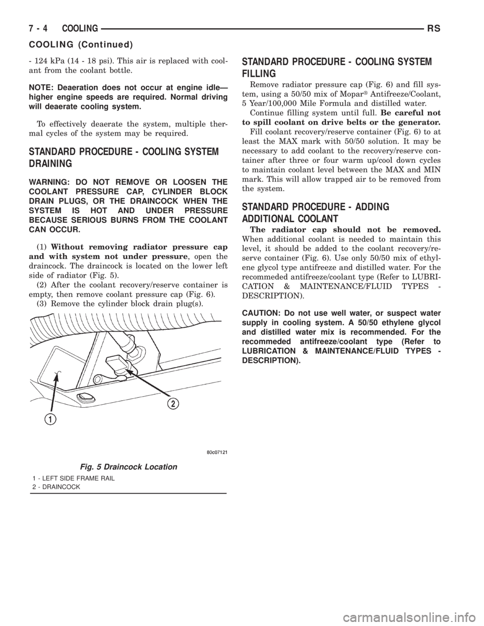
draincock. The draincock is located on the lower left
side of radiator (Fig. 5).
(2) After the coolant recovery/reserve container is
empty, then remove coolant pressure cap (Fig. 6).
(3) Remove the cylinder block drain plug(s).
STANDARD PROCEDURE - COOLING SYSTEM
FILLING
Remove radiator pressure cap (Fig. 6) and fill sys-
tem, using a 50/50 mix of MopartAntifreeze/Coolant,
5 Year/100,000 Mile Formula and distilled water.
Continue filling system until full.Be careful not
to spill coolant on drive belts or the generator.
Fill coolant recovery/reserve container (Fig. 6) to at
least the MAX mark with 50/50 solution. It may be
necessary to add coolant to the recovery/reserve con-
tainer after three or four warm up/cool down cycles
to maintain coolant level between the MAX and MIN
mark. This will allow trapped air to be removed from
the system.
STANDARD PROCEDURE - ADDING
ADDITIONAL COOLANT
The radiator cap should not be removed.
When additional coolant is needed to maintain this
level, it should be added to the coolant recovery/re-
serve container (Fig. 6). Use only 50/50 mix of ethyl-
ene glycol type antifreeze and distilled water. For the
recommeded antifreeze/coolant type (Refer to LUBRI-
CATION & MAINTENANCE/FLUID TYPES -
DESCRIPTION).
CAUTION: Do not use well water, or suspect water
supply in cooling system. A 50/50 ethylene glycol
and distilled water mix is recommended. For the
recommeded antifreeze/coolant type (Refer to
LUBRICATION & MAINTENANCE/FLUID TYPES -
DESCRIPTION).
Fig. 5 Draincock Location
1 - LEFT SIDE FRAME RAIL
2 - DRAINCOCK
7 - 4 COOLINGRS
COOLING (Continued)
Page 1753 of 4284
DIAGNOSIS AND TESTING - COOLANT
RECOVERY SYSTEM
The cooling system is closed and designed to main-
tain coolant level to the top of the radiator.
(1) With the engineoffand cooling systemnot
under pressure, drain several ounces of coolant from
the radiator draincock while observing the coolant
recovery container. Coolant level in the container
should drop.
(2) Remove the radiator pressure cap. The coolant
level should be full to the top radiator neck. If not,
and the coolant level in the container is at or above
the MIN mark, there is an air leak in the coolant
recovery system.
(3) Check hose and hose connections to the con-
tainer, radiator filler neck or the pressure cap seal to
the radiator filler neck for leaks.
REMOVAL
(1) Raise the vehicle on hoist.
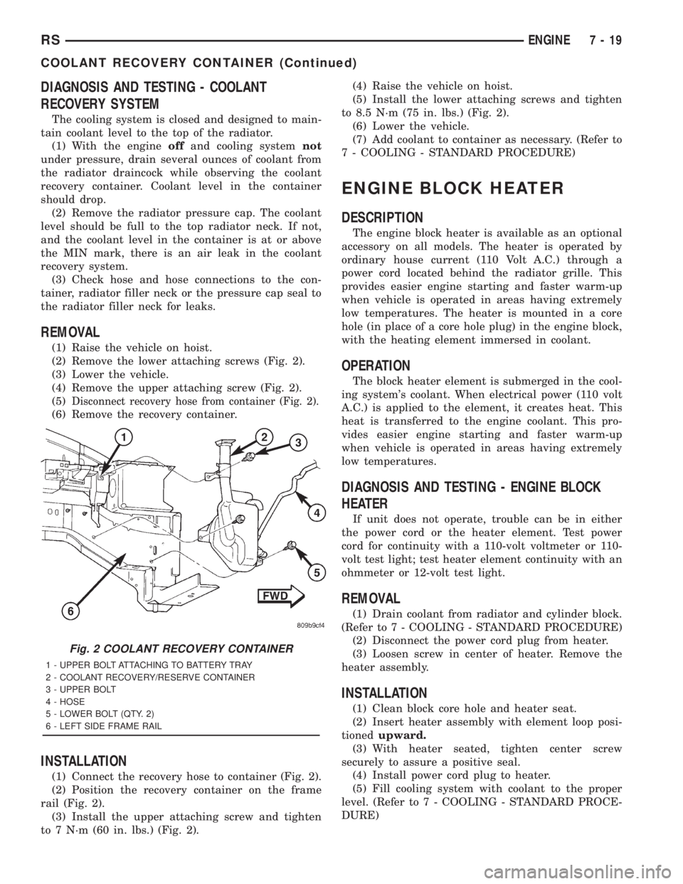
(2) Remove the lower attaching screws (Fig. 2).
(3) Lower the vehicle.
(4) Remove the upper attaching screw (Fig. 2).
(5)
Disconnect recovery hose from container (Fig. 2).
(6) Remove the recovery container.
INSTALLATION
(1) Connect the recovery hose to container (Fig. 2).
(2) Position the recovery container on the frame
rail (Fig. 2).
(3) Install the upper attaching screw and tighten
to 7 N´m (60 in. lbs.) (Fig. 2).(4) Raise the vehicle on hoist.
(5) Install the lower attaching screws and tighten
to 8.5 N´m (75 in. lbs.) (Fig. 2).
(6) Lower the vehicle.
(7) Add coolant to container as necessary. (Refer to
7 - COOLING - STANDARD PROCEDURE)
ENGINE BLOCK HEATER
DESCRIPTION
The engine block heater is available as an optional
accessory on all models. The heater is operated by
ordinary house current (110 Volt A.C.) through a
power cord located behind the radiator grille. This
provides easier engine starting and faster warm-up
when vehicle is operated in areas having extremely
low temperatures. The heater is mounted in a core
hole (in place of a core hole plug) in the engine block,
with the heating element immersed in coolant.
OPERATION
The block heater element is submerged in the cool-
ing system's coolant. When electrical power (110 volt
A.C.) is applied to the element, it creates heat. This
heat is transferred to the engine coolant. This pro-
vides easier engine starting and faster warm-up
when vehicle is operated in areas having extremely
low temperatures.
DIAGNOSIS AND TESTING - ENGINE BLOCK
HEATER
If unit does not operate, trouble can be in either
the power cord or the heater element. Test power
cord for continuity with a 110-volt voltmeter or 110-
volt test light; test heater element continuity with an
ohmmeter or 12-volt test light.
REMOVAL
(1) Drain coolant from radiator and cylinder block.
(Refer to 7 - COOLING - STANDARD PROCEDURE)
(2) Disconnect the power cord plug from heater.
(3) Loosen screw in center of heater. Remove the
heater assembly.
INSTALLATION
(1) Clean block core hole and heater seat.
(2) Insert heater assembly with element loop posi-
tionedupward.
(3) With heater seated, tighten center screw
securely to assure a positive seal.
(4) Install power cord plug to heater.
(5) Fill cooling system with coolant to the proper
level. (Refer to 7 - COOLING - STANDARD PROCE-
DURE)
Fig. 2 COOLANT RECOVERY CONTAINER
1 - UPPER BOLT ATTACHING TO BATTERY TRAY
2 - COOLANT RECOVERY/RESERVE CONTAINER
3 - UPPER BOLT
4 - HOSE
5 - LOWER BOLT (QTY. 2)
6 - LEFT SIDE FRAME RAIL
RSENGINE7-19
COOLANT RECOVERY CONTAINER (Continued)
Page 1813 of 4284
OK, repair the open circuit to the battery as
required.
(3) Turn the ignition switch to the ON position.
Check for battery voltage at the fuse in the junction
block. If OK, go to Step 4. If not OK, repair the open
circuit to the ignition switch as required.
(4) Turn the ignition switch to the OFF position.
Disconnect and isolate the battery negative cable.
Remove the radio, but do not unplug the wire har-
ness connectors. Check for continuity between the
radio chassis and a good ground. There should be
continuity. If OK, go to Step 5. If not OK, repair the
open radio chassis ground circuit as required.
(5) Connect the battery negative cable. Turn the
ignition switch to the ON position. Check for battery
voltage at the fused ignition switch output circuit
cavity of the left (gray) radio wire harness connector.
If OK, go to Step 6. If not OK, repair the open circuit
as required.
(6) Turn the ignition switch to the OFF position.
Check for battery voltage at the fused B(+) circuit
cavity of the left (gray) radio wire harness connector.
If OK, replace the faulty radio. If not OK, repair the
open circuit to the Ignition-Off Draw (IOD) fuse as
required.
REMOVAL
(1) Disconnect and isolate the battery negative
cable.
(2) Remove cup holder.
(3) Remove trim panel above cupholder by pulling
straight out.
(4) Remove center instrument panel trim panel.
(5) Remove screws holding radio to instrument
panel.
(6) Pull radio rearward to gain access to the back
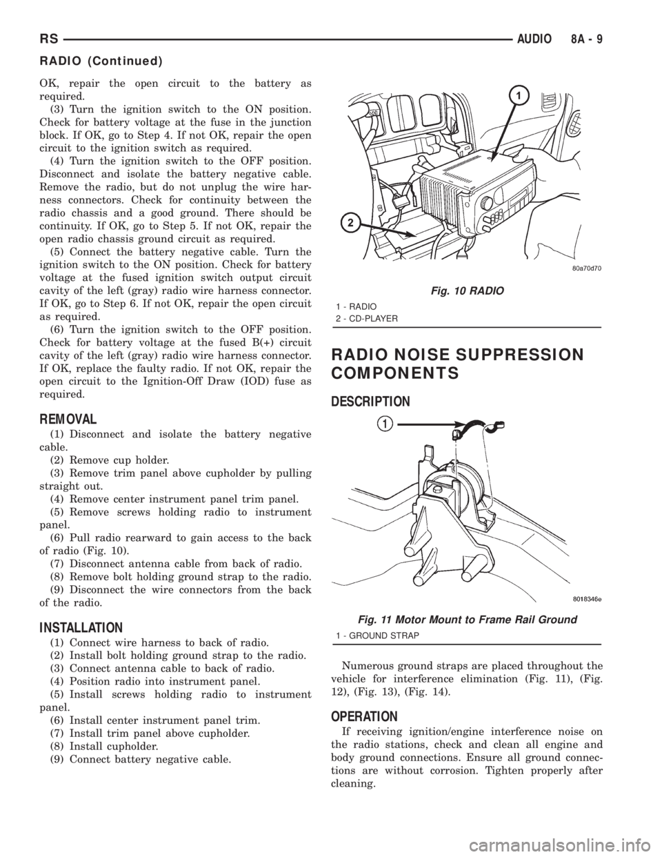
of radio (Fig. 10).
(7) Disconnect antenna cable from back of radio.
(8) Remove bolt holding ground strap to the radio.
(9) Disconnect the wire connectors from the back
of the radio.
INSTALLATION
(1) Connect wire harness to back of radio.
(2) Install bolt holding ground strap to the radio.
(3) Connect antenna cable to back of radio.
(4) Position radio into instrument panel.
(5) Install screws holding radio to instrument
panel.
(6) Install center instrument panel trim.
(7) Install trim panel above cupholder.
(8) Install cupholder.
(9) Connect battery negative cable.
RADIO NOISE SUPPRESSION
COMPONENTS
DESCRIPTION
Numerous ground straps are placed throughout the
vehicle for interference elimination (Fig. 11), (Fig.
12), (Fig. 13), (Fig. 14).
OPERATION
If receiving ignition/engine interference noise on
the radio stations, check and clean all engine and
body ground connections. Ensure all ground connec-
tions are without corrosion. Tighten properly after
cleaning.
Fig. 10 RADIO
1 - RADIO
2 - CD-PLAYER
Fig. 11 Motor Mount to Frame Rail Ground
1 - GROUND STRAP
RSAUDIO8A-9
RADIO (Continued)
Page 1845 of 4284
²Fuel system monitor
²EGR monitor
²Purge system monitor
²All inputs monitored for proper voltage range.
²All monitored components (refer to the Emission
section for On-Board Diagnostics).
The PCM compares the upstream and downstream
heated oxygen sensor inputs to measure catalytic
convertor efficiency. If the catalyst efficiency drops
below the minimum acceptable percentage, the PCM
stores a diagnostic trouble code in memory.
During certain idle conditions, the PCM may enter
a variable idle speed strategy. During variable idle
speed strategy the PCM adjusts engine speed based
on the following inputs.
²A/C sense
²Battery voltage
²Battery temperature
²Engine coolant temperature
²Engine run time
²Inlet/Intake air temperature
²Vehicle mileage
ACCELERATION MODE
This is a CLOSED LOOP mode. The PCM recog-
nizes an abrupt increase in Throttle Position sensor
output voltage or MAP sensor output voltage as a
demand for increased engine output and vehicle
acceleration. The PCM increases injector pulse width
in response to increased fuel demand.
DECELERATION MODE
This is a CLOSED LOOP mode. During decelera-
tion the following inputs are received by the PCM:
²A/C sense
²Battery voltage
²Inlet/Intake air temperature
²Engine coolant temperature
²Crankshaft position (engine speed)
²Exhaust gas oxygen content (upstream heated
oxygen sensor)
²Knock sensor
²Manifold absolute pressure
²Throttle position
²IAC motor control changes in response to MAP
sensor feedback
The PCM may receive a closed throttle input from
the Throttle Position Sensor (TPS) when it senses an
abrupt decrease in manifold pressure. This indicates
a hard deceleration. In response, the PCM may
momentarily turn off the injectors. This helps
improve fuel economy, emissions and engine braking.
WIDE-OPEN-THROTTLE MODE
This is an OPEN LOOP mode. During wide-open-
throttle operation, the following inputs are used by
the PCM:
²Inlet/Intake air temperature
²Engine coolant temperature
²Engine speed
²Knock sensor
²Manifold absolute pressure
²Throttle position
When the PCM senses a wide-open-throttle condi-
tion through the Throttle Position Sensor (TPS) it de-
energizes the A/C compressor clutch relay. This
disables the air conditioning system.
The PCM does not monitor the heated oxygen sen-
sor inputs during wide-open-throttle operation except
for downstream heated oxygen sensor and both
shorted diagnostics. The PCM adjusts injector pulse
width to supply a predetermined amount of addi-
tional fuel.
IGNITION SWITCH OFF MODE
When the operator turns the ignition switch to the
OFF position, the following occurs:
²All outputs are turned off, unless 02 Heater
Monitor test is being run. Refer to the Emission sec-
tion for On-Board Diagnostics.
²No inputs are monitored except for the heated
oxygen sensors. The PCM monitors the heating ele-
ments in the oxygen sensors and then shuts down.
STANDARD PROCEDURES - OBTAINING
DIAGNOSTIC TROUBLE CODES
BULB CHECK
Each time the ignition key is turned to the ON
position, the malfunction indicator (check engine)
lamp on the instrument panel should illuminate for
approximately 2 seconds then go out. This is done for
a bulb check. When the key is in the power on, but
engine off position, the MIL will remain illuminated
for regulatory purposes.
OBTAINING DTC'S USING DRB SCAN TOOL
(1) Connect the DRB scan tool to the data link
(diagnostic) connector. This connector is located in
the passenger compartment; at the lower edge of
instrument panel; near the steering column.
(2) Turn the ignition switch on and access the
ªRead Faultº screen.
(3) Record all the DTC's and ªfreeze frameº infor-
mation shown on the DRB scan tool.
RSELECTRONIC CONTROL MODULES8E-21
POWERTRAIN CONTROL MODULE (Continued)
Page 1848 of 4284
Control Module. The sliding door control module con-
tains software technology which enables it to detect
resistance to door travel and to reverse door travel in
order to avoid damage to the door or to avoid possible
personal injury if the obstruction is a person. This
feature functions in both the opening and closing
cycles. If the power sliding door system develops any
problems the control module will store and recall
Diagnostic Trouble Codes (DTC). The use of a diag-
nostic scan tool, such as the DRB IIItis required to
read and troubleshoot these trouble codes. The slid-
ing door control module can be reflashed if necessary.
Refer to the latest Technical Service Bulletin (TSB)
Information for any updates.
The power door control module is a replaceable
component and cannot be repaired, if found to be
faulty it must be replaced. Consult your Mopary
parts catalog for a specific part number.
OPERATION
The power sliding door control module serves as
the main computer for the power sliding side door
system. All power door functions are processed
through the power door control module and/or the
vehicles body control module (BCM). At the start of a
power open command, a signal is sent to the BCM
and then to the power door control module via the
J1850 data bus circuit. This signal, generated by any
of the power door command switches, tells the power
door control module to activate a power latch release,
engage the clutch assembly and drive the door into
the full open position. If an obstacle is felt during
this power open cycle, the module will reverse direc-
tion and close the door. This process is also enabled
during a power close cycle. This process will repeat
three times, and if a fourth obstacle is detected, the
door will go into full manual mode. Once the full
open position is obtained, a hold open latch assembly
mounted full open switch tells the control module
that the door has reached the full open position. If
the power sliding door system develops any problems
the control module will store and recall Diagnostic
Trouble Codes (DTC). The use of a diagnostic scan
tool, such as the DRB IIItis required to read and
troubleshoot these trouble codes.
REMOVAL
(1) Disconnect and isolate the negative battery
cable.
(2) Remove the appropriate door trim panel from
the vehicle. Refer to Body for the procedure.
(3) Remove the weather shield. Refer to Body for
the procedure.
(4) Disconnect the power door control module elec-
trical connectors. Slide the red locking tab out (awayfrom module) and depress connector retaining tab,
while pulling straight apart.
(5) Remove the control module retaining screw.
(6) Remove the module from the vehicle.
INSTALLATION
(1) Position the control module and install the
retaining screw.
(2) Connect the control module electrical connec-
tors. Slide the locking tab into the locked position.
(3) Install the appropriate door trim panel on the
vehicle. Refer to Body for the procedure.
(4) Install the weather shield. Refer to Body for
the procedure.
(5) Connect the negative battery cable.
(6) Using an appropriate scan tool, check and
erase any power door control module diagnostic trou-
ble codes.
(7) Verify power door system operation. Cycle the
power door through one complete open and close
cycle.
TRANSMISSION CONTROL
MODULE
DESCRIPTION
The Transmission Control Module (TCM) is located
behind the left fender and is fastened with three
screws to three clips in the left frame rail forward of
the suspension (Fig. 13).
OPERATION
The TCM is the controlling unit for all electronic
operations of the transaxle. The TCM receives infor-
mation regarding vehicle operation from both direct
and indirect inputs, and selects the operational mode
of the transaxle. Direct inputs are hardwired to, and
used specifically by the TCM. Indirect inputs origi-
nate from other components/modules, and are shared
with the TCM via the communication bus.
Some examples ofdirect inputsto the TCM are:
²Battery (B+) voltage
²Ignition ªONº voltage
²Transmission Control Relay (Switched B+)
²Throttle Position Sensor
²Crankshaft Position Sensor (CKP)
²Transmission Range Sensor (TRS)
²Pressure Switches (L/R, 2/4, OD)
²Transmission Temperature Sensor (Integral to
TRS)
²Input Shaft Speed Sensor
8E - 24 ELECTRONIC CONTROL MODULESRS
SLIDING DOOR CONTROL MODULE (Continued)
Page 1861 of 4284
material protrude from the top of the molded plastic
battery case to provide the means for connecting the
battery to the vehicle electrical system. The battery
positive terminal post is visibly larger in diameter
than the negative terminal post, for easy identification.
The lettersPOS
andNEGare also molded into the
top of the battery case adjacent to their respective
positive and negative terminal posts for additional
identification confirmation. Refer toBattery Cables
in the index of this service manual for the location of
more information on the battery cables that connect
the battery to the vehicle electrical system.
This battery is designed to provide a safe, efficient
and reliable means of storing electrical energy in a
chemical form. This means of energy storage allows
the battery to produce the electrical energy required
to operate the engine starting system, as well as to
operate many of the other vehicle accessory systems
for limited durations while the engine and/or the
charging system are not operating. The battery is
made up of six individual cells that are connected in
series. Each cell contains positively charged plate
groups that are connected with lead straps to the
positive terminal post, and negatively charged plate
groups that are connected with lead straps to the
negative terminal post. Each plate consists of a stiff
mesh framework or grid coated with lead dioxide
(positive plate) or sponge lead (negative plate). Insu-
lators or plate separators made of a non-conductive
material are inserted between the positive and nega-
tive plates to prevent them from contacting or short-
ing against one another. These dissimilar metal
plates are submerged in a sulfuric acid and water
solution called an electrolyte.
Some factory-installed batteries have a built-in test
indicator (hydrometer). The color visible in the sight
glass of the indicator will reveal the battery condi-
tion. For more information on the use of the built-in
test indicator, refer toStandard Procedures The
factory-installed low-maintenance battery has
removable battery cell caps.Distilled water can
be added to this battery. The battery is not sealed
and has vent holes in the cell caps. The chemical
composition of the metal coated plates within the
low-maintenance battery reduces battery gassing and
water loss, at normal charge and discharge rates.
Therefore, the battery should not require additional
water in normal service. If the electrolyte level in
this battery does become low, distilled water must be
added. However, rapid loss of electrolyte can be
caused by an overcharging condition. Be certain to
diagnose the charging system after replenishing the
water in the battery for a low electrolyte condition
and before returning the vehicle to service. Refer to
Charging Systemfor additional information.The battery Group Size number, the Cold Cranking
Amperage (CCA) rating, and the Reserve Capacity
(RC) rating or Ampere-Hours (AH) rating can be
found on the original equipment battery label. Be
certain that a replacement battery has the correct
Group Size number, as well as CCA, and RC or AH
ratings that equal or exceed the original equipment
specification for the vehicle being serviced. Refer to
Battery Specificationsin this group for the loca-
tion of the proper factory-installed battery specifica-
tions. Battery sizes and ratings are discussed in more
detail below.
Group Size
²The outside dimensions and terminal placement
of the battery conform to standards established by
the Battery Council International (BCI). Each bat-
tery is assigned a BCI Group Size number to help
identify a correctly-sized replacement.
Cold Cranking Amperage
²The Cold Cranking Amperage (CCA) rating spec-
ifies how much current (in amperes) the battery can
deliver for thirty seconds at -18É C (0É F). Terminal
voltage must not fall below 7.2 volts during or after
the thirty second discharge period. The CCA required
is generally higher as engine displacement increases,
depending also upon the starter current draw
requirements.
Reserve Capacity
²The Reserve Capacity (RC) rating specifies the
time (in minutes) it takes for battery terminal volt-
age to fall below 10.5 volts, at a discharge rate of 25
amperes. RC is determined with the battery fully-
charged at 26.7É C (80É F). This rating estimates how
long the battery might last after a charging system
failure, under minimum electrical load.
Ampere-Hours
²The Ampere-Hours (AH) rating specifies the cur-
rent (in amperes) that a battery can deliver steadily
for twenty hours, with the voltage in the battery not
falling below 10.5 volts. This rating is also sometimes
identified as the twenty-hour discharge rating.
OPERATION
The battery is designed to store electrical energy in
a chemical form. When an electrical load is applied to
the terminals of the battery, an electrochemical reac-
tion occurs. This reaction causes the battery to dis-
charge electrical current from its terminals. As the
RSBATTERY SYSTEM8F-7
BATTERY (Continued)
Page 1907 of 4284
OPERATION
The heated seat elements resist the flow of electri-
cal current. When battery current is passed through
the elements, the energy lost by the resistance of the
elements to the current flow is released in the form
of heat. The temperature sensor is a NTC thermistor.
When the temperature of the seat cushion cover
rises, the resistance of the sensor decreases. The
HSM or MHSM supplies a five-volt current to one
side of each sensor, and monitors the voltage drop
through the sensor on a return circuit. The MSM or
MHSM uses this temperature sensor input to moni-
tor the temperature of the seat, and regulates the
current flow to the seat heating elements accordingly.
DIAGNOSIS & TESTING - HEATED SEAT
ELEMENT
The wire harness connectors for the seat cushion
and seat back heating elements are located under the
seat, near the rear edge of the seat cushion frame.
For circuit descriptions and diagrams, refer to Group
8W, Wiring Diagrams.
SEAT CUSHION
(1) Disconnect and isolate the battery negative
cable. Unplug the 4-way heated seat cushion wire
harness connector.
(2) Check for continuity between the two heated
seat driver circuit cavities of the seat cushion cover
half of the heated seat cushion wire harness connec-
tor. There should be continuity. If OK, go to Step 3. If
not OK, replace the faulty seat cushion cover.
(3) Check for continuity between one of the heated
seat driver circuit cavities of the seat cushion cover
half of the heated seat cushion wire harness connec-
tor and the seat cushion frame. There should be no
continuity. If OK, go to the Seat Back test. If not OK,
replace the faulty seat cushion cover.
SEAT BACK
(1) Disconnect and isolate the battery negative
cable. Unplug the 2-way heated seat back wire har-
ness connector.
(2) Check for continuity between the heated seat
driver circuit cavity and the ground circuit cavity of
the seat back cover half of the heated seat back wire
harness connector. There should be continuity. If OK,
go to Step 3. If not OK, replace the faulty seat back
cover.
(3) Check for continuity between the heated seat
driver circuit cavity of the seat back cover half of the
heated seat back wire harness connector and the seat
back frame. There should be no continuity. If OK,
test the heated seat sensor as described in this
group. If not OK, replace the faulty seat back cover.
HEATED SEAT SENSOR
DESCRIPTION
The heated seat temperature sensor is a Negative
Temperature Coefficient (NTC) thermistor. One tem-
perature sensor is used for each seat, and is inte-
grated into the seat cushion heating element.
DIAGNOSIS & TESTING - HEATED SEAT
SENSOR
For complete circuit diagrams, refer toWiring
Diagrams.
(1) Disconnect and isolate the battery negative
cable. Disconnect the 4-way heated seat cushion ele-
ment wire harness connector from the power seat
wire harness. The power seat wire harness connec-
tors for the seat cushion and seat back heating ele-
ments are secured to a bracket located under the
rear edge of the seat cushion frame.
(2) Using an ohmmeter, check the resistance
between the seat sensor circuit and the seat temper-
ature sensor input circuit cavities of the 4-way
heated seat cushion element wire harness connector.
The sensor resistance should be between 2 kilohms
at 15É C (60É F) and 200 kilohms at 30É C (85É F). If
not OK, replace the faulty seat cushion cover trim
and sensor unit.
PASSENGER HEATED SEAT
SWITCH
DESCRIPTION
The heated seat switches are mounted in the
instrument panel center bezel (Fig. 5). The two three-
position rocker-type switches, one switch for each
front seat, are incorporated into one large switch
assembly that also includes the hazzard, rear window
wiper and washer switches. The heated seat switches
provide a resistor multiplexed signal to the Body
Control Module (BCM) through separate hard wired
circuits. Each switch has an Off, Low, and High posi-
tion so that both the driver and the front seat pas-
senger can select a preferred seat heating mode.
Each switch has two Light-Emitting Diodes (LED)
which light to indicate that the heater for the seat is
turned on.
The heated seat switches and their LEDs cannot
be repaired. If either switch or LED is faulty or dam-
aged, the entire switch assembly must be replaced.
OPERATION
There are three positions that can be selected with
each of the heated seat switches: Off, Low, or High.
When the left side of the switch rocker is fully
RSHEATED SEAT SYSTEM8G-11
HEATED SEAT ELEMENT (Continued)
Page 2033 of 4284
limit of the adjuster is reached. When the switch is
moved in the opposite direction, the battery feed and
ground path to the motor are reversed through the
switch contacts. This causes the adjuster motor to
run in the opposite direction.
No power seat switch should be held applied in any
direction after the adjuster has reached its travel
limit. The power seat adjuster motors each contain a
self-resetting circuit breaker to protect them from
overload. However, consecutive or frequent resetting
of the circuit breaker must not be allowed to con-
tinue, or the motor may be damaged.
DIAGNOSIS AND TESTING - DRIVER SEAT
SWITCH
(1) Remove switch, refer to Switch Removal and
Installation in this section.
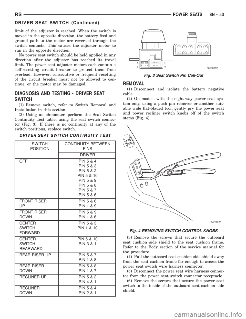
(2) Using an ohmmeter, perform the Seat Switch
Continuity Test table, using the seat switch connec-
tor (Fig. 3). If there is no continuity at any of the
switch positions, replace switch.
DRIVER SEAT SWITCH CONTINUITY TEST
SWITCH
POSITIONCONTINUITY BETWEEN
PINS
DRIVER
OFF PIN5&4
PIN5&3
PIN5&2
PIN5&10
PIN5&9
PIN5&8
PIN5&7
PIN5&6
FRONT RISER
UPPIN5&6
PIN1&9
FRONT RISER
DOWNPIN5&9
PIN1&6
CENTER
SWITCH
FORWARDPIN5&3
PIN1&10
CENTER
SWITCH
REARWARDPIN5&10
PIN3&1
REAR RISER UP PIN5&7
PIN1&8
REAR RISER
DOWNPIN5&8
PIN1&7
RECLINER UP PIN5&2
PIN4&1
RECLINER
DOWNPIN5&4
PIN2&1
REMOVAL
(1) Disconnect and isolate the battery negative
cable.
(2) On models with the eight-way power seat sys-
tem only, using a push pin remover or another suit-
able wide flat-bladed tool, gently pry the power seat
and power recliner switch knobs off of the switch
stems (Fig. 4).
(3) Remove the screws that secure the outboard
seat cushion side shield to the seat cushion frame.
Refer to the Body section of the service manual for
the procedure.
(4) Pull the outboard seat cushion side shield away
from the seat cushion frame far enough to access the
power seat switch wire harness connector.
(5) Disconnect the power seat wire harness connec-
tor from the power seat switch connector receptacle.
(6) Remove the screws that secure the power seat
switch to the inside of the outboard seat cushion side
shield.
Fig. 3 Seat Switch Pin Call-Out
Fig. 4 REMOVING SWITCH CONTROL KNOBS
RSPOWER SEATS8N-53
DRIVER SEAT SWITCH (Continued)