2001 CHRYSLER VOYAGER frame
[x] Cancel search: framePage 2708 of 4284
(53) Lower the vehicle.
(54) Remove the power steering pump and set
aside.
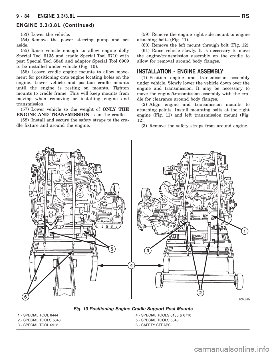
(55) Raise vehicle enough to allow engine dolly
Special Tool 6135 and cradle Special Tool 6710 with
post Special Tool 6848 and adaptor Special Tool 6909
to be installed under vehicle (Fig. 10).
(56) Loosen cradle engine mounts to allow move-
ment for positioning onto engine locating holes on the
engine. Lower vehicle and position cradle mounts
until the engine is resting on mounts. Tighten
mounts to cradle frame. This will keep mounts from
moving when removing or installing engine and
transmission.
(57) Lower vehicle so the weight ofONLY THE
ENGINE AND TRANSMISSIONis on the cradle.
(58) Install and secure the safety straps to the cra-
dle fixture and around the engine.(59) Remove the engine right side mount to engine
attaching bolts (Fig. 11).
(60) Remove the left mount through bolt (Fig. 12).
(61) Raise vehicle slowly. It is necessary to move
the engine/transmission assembly on the cradle to
allow for removal around body flanges.
INSTALLATION - ENGINE ASSEMBLY
(1) Position engine and transmission assembly
under vehicle. Slowly lower the vehicle down over the
engine and transmission. It may be necessary to
move the engine/transmission assembly with the cra-
dle for clearance around body flanges.
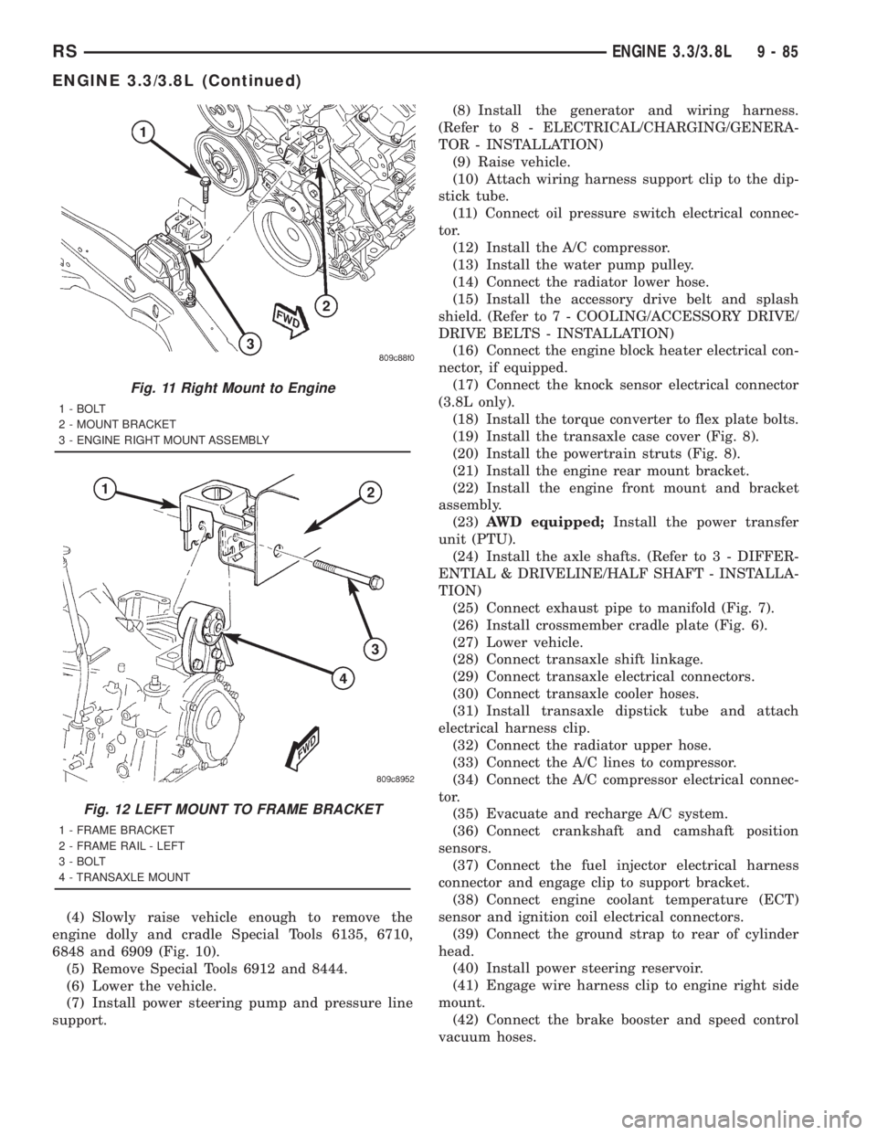
(2) Align engine and transmission mounts to
attaching points. Install mounting bolts at the right
engine (Fig. 11) and left transmission mount (Fig.
12).
(3) Remove the safety straps from around engine.
Fig. 10 Positioning Engine Cradle Support Post Mounts
1 - SPECIAL TOOL 8444 4 - SPECIAL TOOLS 6135 & 6710
2 - SPECIAL TOOLS 6848 5 - SPECIAL TOOLS 6848
3 - SPECIAL TOOL 6912 6 - SAFETY STRAPS
9 - 84 ENGINE 3.3/3.8LRS
ENGINE 3.3/3.8L (Continued)
Page 2709 of 4284
(4) Slowly raise vehicle enough to remove the
engine dolly and cradle Special Tools 6135, 6710,
6848 and 6909 (Fig. 10).
(5) Remove Special Tools 6912 and 8444.
(6) Lower the vehicle.
(7) Install power steering pump and pressure line
support.(8) Install the generator and wiring harness.
(Refer to 8 - ELECTRICAL/CHARGING/GENERA-
TOR - INSTALLATION)
(9) Raise vehicle.
(10) Attach wiring harness support clip to the dip-
stick tube.
(11) Connect oil pressure switch electrical connec-
tor.
(12) Install the A/C compressor.
(13) Install the water pump pulley.
(14) Connect the radiator lower hose.
(15) Install the accessory drive belt and splash
shield. (Refer to 7 - COOLING/ACCESSORY DRIVE/
DRIVE BELTS - INSTALLATION)
(16) Connect the engine block heater electrical con-
nector, if equipped.
(17) Connect the knock sensor electrical connector
(3.8L only).
(18) Install the torque converter to flex plate bolts.
(19) Install the transaxle case cover (Fig. 8).
(20) Install the powertrain struts (Fig. 8).
(21) Install the engine rear mount bracket.
(22) Install the engine front mount and bracket
assembly.
(23)AWD equipped;Install the power transfer
unit (PTU).
(24) Install the axle shafts. (Refer to 3 - DIFFER-
ENTIAL & DRIVELINE/HALF SHAFT - INSTALLA-
TION)
(25) Connect exhaust pipe to manifold (Fig. 7).
(26) Install crossmember cradle plate (Fig. 6).
(27) Lower vehicle.
(28) Connect transaxle shift linkage.
(29) Connect transaxle electrical connectors.
(30) Connect transaxle cooler hoses.
(31) Install transaxle dipstick tube and attach
electrical harness clip.
(32) Connect the radiator upper hose.
(33) Connect the A/C lines to compressor.
(34) Connect the A/C compressor electrical connec-
tor.
(35) Evacuate and recharge A/C system.
(36) Connect crankshaft and camshaft position
sensors.
(37) Connect the fuel injector electrical harness
connector and engage clip to support bracket.
(38) Connect engine coolant temperature (ECT)
sensor and ignition coil electrical connectors.
(39) Connect the ground strap to rear of cylinder
head.
(40) Install power steering reservoir.
(41) Engage wire harness clip to engine right side
mount.
(42) Connect the brake booster and speed control
vacuum hoses.
Fig. 11 Right Mount to Engine
1 - BOLT
2 - MOUNT BRACKET
3 - ENGINE RIGHT MOUNT ASSEMBLY
Fig. 12 LEFT MOUNT TO FRAME BRACKET
1 - FRAME BRACKET
2 - FRAME RAIL - LEFT
3 - BOLT
4 - TRANSAXLE MOUNT
RSENGINE 3.3/3.8L9-85
ENGINE 3.3/3.8L (Continued)
Page 2751 of 4284
ENGINE MOUNTING
DESCRIPTION
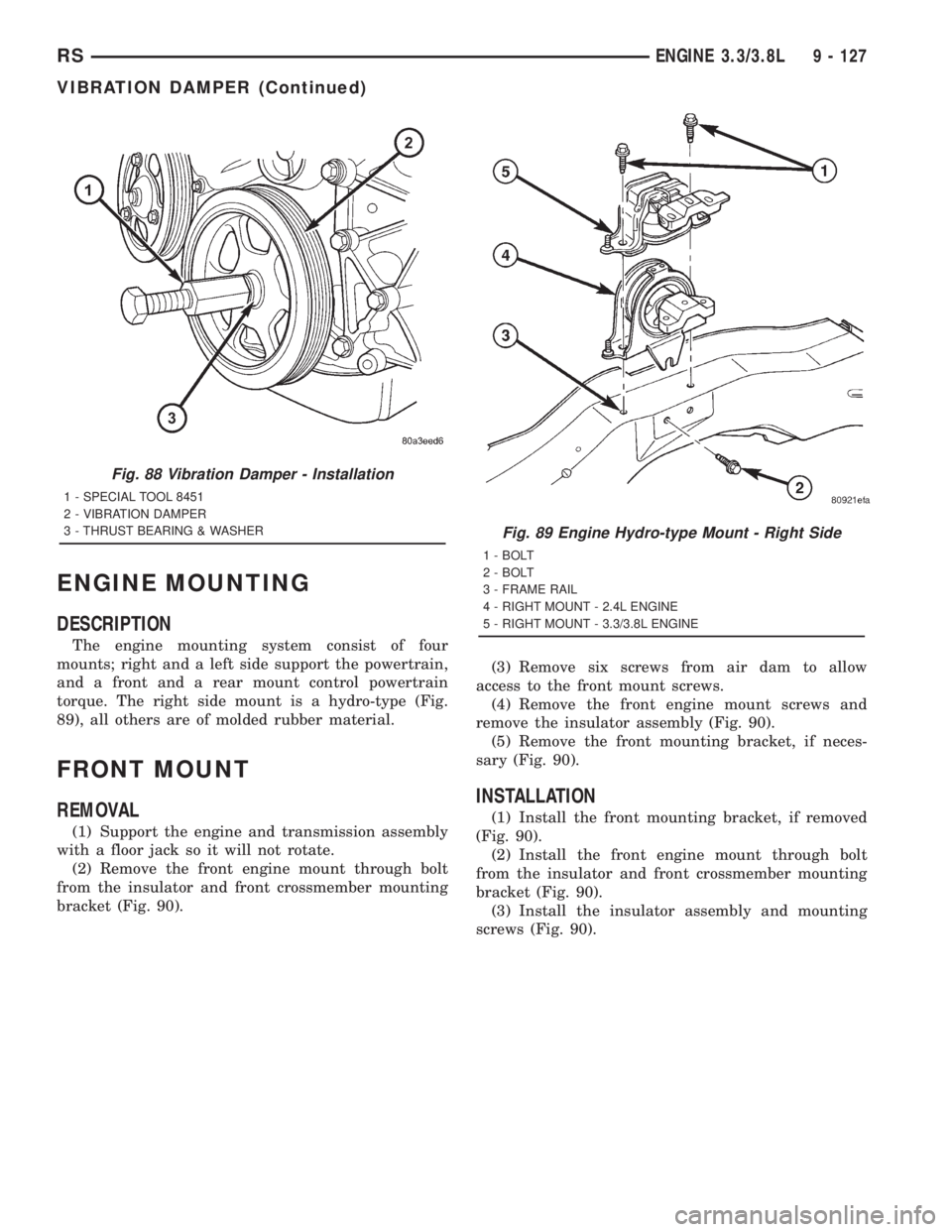
The engine mounting system consist of four
mounts; right and a left side support the powertrain,
and a front and a rear mount control powertrain
torque. The right side mount is a hydro-type (Fig.
89), all others are of molded rubber material.
FRONT MOUNT
REMOVAL
(1) Support the engine and transmission assembly
with a floor jack so it will not rotate.
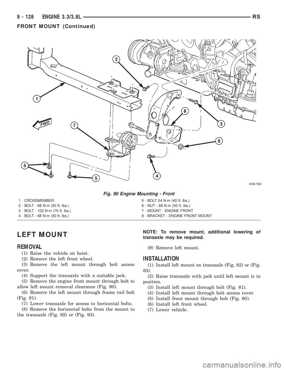
(2) Remove the front engine mount through bolt
from the insulator and front crossmember mounting
bracket (Fig. 90).(3) Remove six screws from air dam to allow
access to the front mount screws.
(4) Remove the front engine mount screws and
remove the insulator assembly (Fig. 90).
(5) Remove the front mounting bracket, if neces-
sary (Fig. 90).
INSTALLATION
(1) Install the front mounting bracket, if removed
(Fig. 90).
(2) Install the front engine mount through bolt
from the insulator and front crossmember mounting
bracket (Fig. 90).
(3) Install the insulator assembly and mounting
screws (Fig. 90).
Fig. 88 Vibration Damper - Installation
1 - SPECIAL TOOL 8451
2 - VIBRATION DAMPER
3 - THRUST BEARING & WASHER
Fig. 89 Engine Hydro-type Mount - Right Side
1 - BOLT
2 - BOLT
3 - FRAME RAIL
4 - RIGHT MOUNT - 2.4L ENGINE
5 - RIGHT MOUNT - 3.3/3.8L ENGINE
RSENGINE 3.3/3.8L9 - 127
VIBRATION DAMPER (Continued)
Page 2752 of 4284
LEFT MOUNT
REMOVAL
(1) Raise the vehicle on hoist.
(2) Remove the left front wheel.
(3) Remove the left mount through bolt access
cover.
(4) Support the transaxle with a suitable jack.
(5) Remove the engine front mount through bolt to
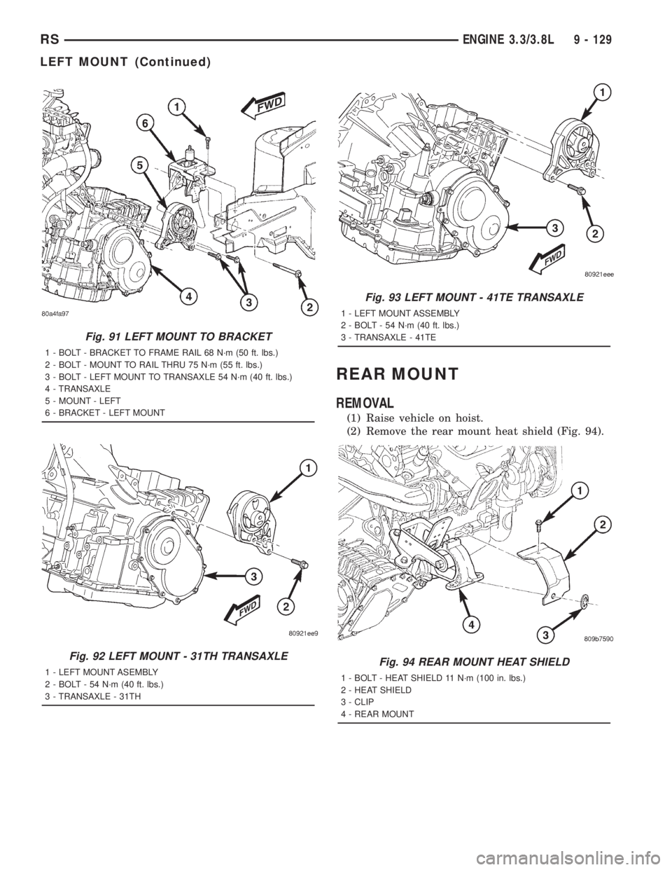
allow left mount removal clearance (Fig. 90).
(6) Remove the left mount through frame rail bolt
(Fig. 91).
(7) Lower transaxle for access to horizontal bolts.
(8) Remove the horizontal bolts from the mount to
the transaxle (Fig. 92) or (Fig. 93).NOTE: To remove mount, additional lowering of
transaxle may be required.
(9) Remove left mount.
INSTALLATION
(1) Install left mount on transaxle (Fig. 82) or (Fig.
83).
(2) Raise transaxle with jack until left mount is in
position.
(3) Install left mount through bolt (Fig. 81).
(4) Install left mount through bolt access cover.
(5) Install front mount through bolt (Fig. 80).
(6) Install left front wheel.
(7) Lower vehicle.
Fig. 90 Engine Mounting - Front
1 - CROSSMEMBER 5 - BOLT 54 N´m (40 ft. lbs.)
2 - BOLT - 68 N´m (50 ft. lbs.) 6 - NUT - 68 N´m (50 ft. lbs.)
3 - BOLT - 102 N´m (75 ft. lbs.) 7 - MOUNT - ENGINE FRONT
4 - BOLT - 68 N´m (50 ft. lbs.) 8 - BRACKET - ENGINE FRONT MOUNT
9 - 128 ENGINE 3.3/3.8LRS
FRONT MOUNT (Continued)
Page 2753 of 4284
REAR MOUNT
REMOVAL
(1) Raise vehicle on hoist.
(2) Remove the rear mount heat shield (Fig. 94).
Fig. 91 LEFT MOUNT TO BRACKET
1 - BOLT - BRACKET TO FRAME RAIL 68 N´m (50 ft. lbs.)
2 - BOLT - MOUNT TO RAIL THRU 75 N´m (55 ft. lbs.)
3 - BOLT - LEFT MOUNT TO TRANSAXLE 54 N´m (40 ft. lbs.)
4 - TRANSAXLE
5 - MOUNT - LEFT
6 - BRACKET - LEFT MOUNT
Fig. 92 LEFT MOUNT - 31TH TRANSAXLE
1 - LEFT MOUNT ASEMBLY
2 - BOLT - 54 N´m (40 ft. lbs.)
3 - TRANSAXLE - 31TH
Fig. 93 LEFT MOUNT - 41TE TRANSAXLE
1 - LEFT MOUNT ASSEMBLY
2 - BOLT - 54 N´m (40 ft. lbs.)
3 - TRANSAXLE - 41TE
Fig. 94 REAR MOUNT HEAT SHIELD
1 - BOLT - HEAT SHIELD 11 N´m (100 in. lbs.)
2 - HEAT SHIELD
3 - CLIP
4 - REAR MOUNT
RSENGINE 3.3/3.8L9 - 129
LEFT MOUNT (Continued)
Page 2755 of 4284
(4) Remove the load on the right engine mount by
carefully supporting the engine assembly with a floor
jack.
(5) Disconnect electrical harness support clips from
engine mount bracket.
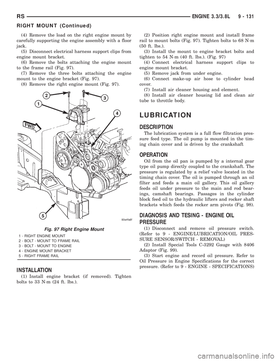
(6) Remove the bolts attaching the engine mount
to the frame rail (Fig. 97).
(7) Remove the three bolts attaching the engine
mount to the engine bracket (Fig. 97).
(8) Remove the right engine mount (Fig. 97).
INSTALLATION
(1) Install engine bracket (if removed). Tighten
bolts to 33 N´m (24 ft. lbs.).(2) Position right engine mount and install frame
rail to mount bolts (Fig. 97). Tighten bolts to 68 N´m
(50 ft. lbs.).
(3) Install the mount to engine bracket bolts and
tighten to 54 N´m (40 ft. lbs.). (Fig. 97)
(4) Connect electrical harness support clips to
engine mount bracket.
(5) Remove jack from under engine.
(6) Connect make-up air hose to cylinder head
cover.
(7) Install air cleaner housing and element.
(8) Install air cleaner housing lid and clean air
tube to throttle body.
LUBRICATION
DESCRIPTION
The lubrication system is a full flow filtration pres-
sure feed type. The oil pump is mounted in the tim-
ing chain cover and is driven by the crankshaft
OPERATION
Oil from the oil pan is pumped by a internal gear
type oil pump directly coupled to the crankshaft. The
pressure is regulated by a relief valve located in the
timing chain cover. The oil is pumped through an oil
filter and feeds a main oil gallery. This oil gallery
feeds oil under pressure to the main and rod bear-
ings, camshaft bearings. Passages in the cylinder
block feed oil to the hydraulic lifters and rocker shaft
brackets which feeds the rocker arm pivots (Fig. 98).
DIAGNOSIS AND TESING - ENGINE OIL
PRESSURE
(1) Disconnect and remove oil pressure switch.
(Refer to 9 - ENGINE/LUBRICATION/OIL PRES-
SURE SENSOR/SWITCH - REMOVAL)
(2) Install Special Tools C-3292 Gauge with 8406
Adaptor (Fig. 99).
(3) Start engine and record oil pressure. Refer to
Oil Pressure in Engine Specifications for the correct
pressure. (Refer to 9 - ENGINE - SPECIFICATIONS)Fig. 97 Right Engine Mount
1 - RIGHT ENGINE MOUNT
2 - BOLT - MOUNT TO FRAME RAIL
3 - BOLT - MOUNT TO ENGINE
4 - ENGINE MOUNT BRACKET
5 - RIGHT FRAME RAIL
RSENGINE 3.3/3.8L9 - 131
RIGHT MOUNT (Continued)
Page 2787 of 4284
(24) Disconnect egr solenoid vacuum line at brake
booster check valve.
(25) Disconnect fuel injector, cam sensor, boost
pressure/intake air temp sensor, fuel rail high pres-
sure, and egr solenoid connectors (Fig. 9).
(26) Disconnect generator electrical connectors.
(27) Disconnect coolant temp sensor and glow plug
electrical connectors.
(28) Disconnect injection pump and A/C compres-
sor electrical connectors.
(29) Disconnect starter electrical connectors.
(30) Disconnect ground wires at engine block.
(31) Raise vehicle on hoist.
(32) Disconnect oil temp sensor, oil pressure sen-
sor, engine speed sensor, and vehicle speed sensor
electrical connector (Fig. 10).
(33) Remove front wheels.
(34) Remove the suspension cradle assembly (Refer
to 13 - FRAME & BUMPERS/FRAME/ENGINE
CRADLE CROSSMEMBER - REMOVAL).
(35) Remove both axle shaft assemblies (Refer to 3
- DIFFERENTIAL & DRIVELINE/HALF SHAFT -
REMOVAL).(36) Disconnect the clutch slave cylinder quick dis-
connect line (RHD only)(Refer to 6 - CLUTCH/SLAVE
CYLINDER - REMOVAL).
(37) Disconnect reverse lamp connector.
(38) Disconnect shifter cables at the tranmission
(Refer to 21 - TRANSMISSION/TRANSAXLE/MAN-
UAL/GEAR SHIFT CABLE - REMOVAL).
(39) Disconnect exhaust pipe from the turbo-
charger downpipe and reposition to right side of vehi-
cle.
(40) Disconnect cabin heater coolant line (Refer to
24 - HEATING & AIR CONDITIONING/CABIN
HEATER/HEATER UNIT - REMOVAL).
(41) Remove front engine mount bracket retaining
bolts from lower radiator support
(42) Lower vehicle. Evacuate the A/C system
(Refer to 24 - HEATING & AIR CONDITIONING/
PLUMBING/REFRIGERANT - STANDARD PROCE-
DURE).
(43) Disconnect the A/C lines at the A/C compres-
sor.
(44) Disconnect the fuel supply and return lines.
(45) Position engine cradle under engine and lower
vehicle over cradle.
(46) Remove right engine mount bolts.
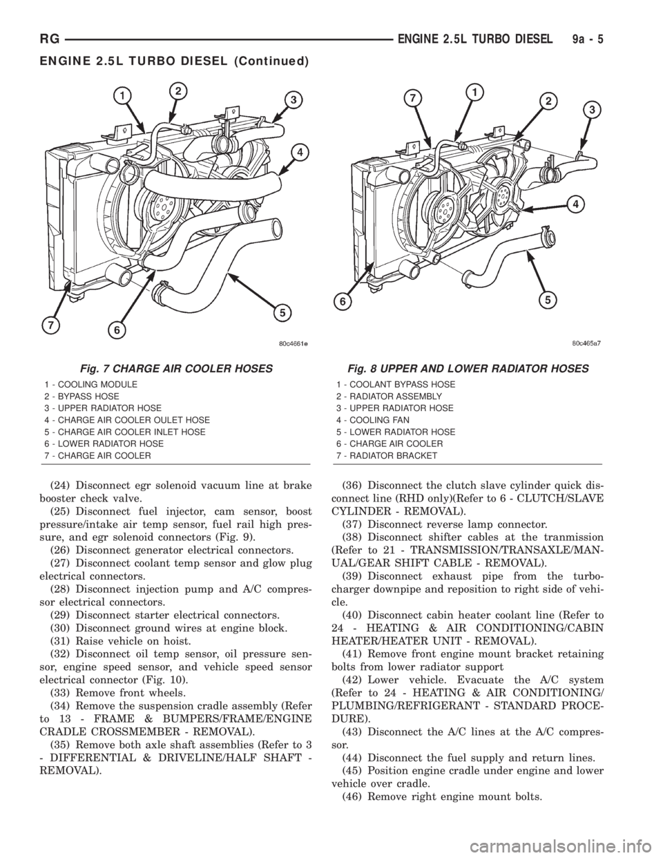
Fig. 7 CHARGE AIR COOLER HOSES
1 - COOLING MODULE
2 - BYPASS HOSE
3 - UPPER RADIATOR HOSE
4 - CHARGE AIR COOLER OULET HOSE
5 - CHARGE AIR COOLER INLET HOSE
6 - LOWER RADIATOR HOSE
7 - CHARGE AIR COOLER
Fig. 8 UPPER AND LOWER RADIATOR HOSES
1 - COOLANT BYPASS HOSE
2 - RADIATOR ASSEMBLY
3 - UPPER RADIATOR HOSE
4 - COOLING FAN
5 - LOWER RADIATOR HOSE
6 - CHARGE AIR COOLER
7 - RADIATOR BRACKET
RGENGINE 2.5L TURBO DIESEL9a-5
ENGINE 2.5L TURBO DIESEL (Continued)
Page 2789 of 4284
(7) Attach front engine mount bracket to lower
radiator support. Torque to 54N´m (40 ft. lbs.)
(8) Connect cabin heater coolant hose.
(9) Connect exhaust pipe to the turbocharger
downpipe flange. Torque to 28 N´m (250 in. lbs.)
(10) Connect reverse lamp electrical connector at
transmission.
(11) Connect both shifter cables (Refer to 21 -
TRANSMISSION/TRANSAXLE/MANUAL/GEAR
SHIFT CABLE - INSTALLATION).
(12) Connect the clutch slave cylinder quick dis-
connect connector (RHD only)(Refer to 6 - CLUTCH/
SLAVE CYLINDER - INSTALLATION).
(13) Install engine harness into bracket on trans-
mission.
(14) Lower vehicle.
(15) Connect fuel supply and return lines.
(16) Connect A/C lines to A/C compressor. Torque
to 23N´m (17 ft. lbs.)
(17) Route engine wiring harnes to proper location.
(18) Connect engine harness ground cables to
engine block
(19) Connect starter solenoid electrical connector
and battery feed wire to starter. Torque to 10N´m (90
in. lbs.)
(20) Connect A/C compressor, injection pump, glow
plugs, and coolant temperature sensor electrical con-
nectors.
(21) Connect generator electrical connector. Torque
to 9N´m (75 in. lbs.)
(22) Connect the fuel injector, fuel pressure sensor,
boost pressure/intake air temp sensor, cam sensor,
and egr solenoid electrical connectors (Fig. 9).
(23) Connect egr solenoid vacuum supply line to
brake boost vacuum supply line.
(24) Connect brake booster vacuum supply line.
(25) Connect heater core return hose to coolant
pipe.
(26) Connect lower radiator hose to engine (Fig. 8).
(27) Install charger air cooler inlet hose (Fig. 7).
(28) Install charge air cooler outlet hose (Fig. 7).
(29) Connect upper radiator hose to engine (Fig.
8).
(30) Install battery shield.
(31) Install coolant reserve pressure container
(Refer to 7 - COOLING/ENGINE/COOLANT RECOV-
ERY PRESS CONTAINER - INSTALLATION).
(32) Install power steering reservoir and bracket
(Fig. 5).
(33) Raise vehicle
(34) Connect oil pressure sensor, oil temperature
sensor, engine speed sensor, and vehicle speed sensor
electrical connector (Fig. 10).(35) Install suspension cradle in vehicle (Refer to
13 - FRAME & BUMPERS/FRAME/ENGINE CRA-
DLE CROSSMEMBER - INSTALLATION).
(36) Install both axle shaft assemblies (Refer to 3 -
DIFFERENTIAL & DRIVELINE/HALF SHAFT -
INSTALLATION).
(37) Connect the power steering supply, pressure,
and return lines to power steering pump (Fig. 5).
(38) Install the power steering line brackets on oil
pan (Fig. 5).
(39) Install lower splash shield and side panels.
(40) Install both front wheel and tire assemblies.
(41) Lower vehicle.
(42) Install air cleaner housing, MAF sensor, and
air intake tube assembly (Fig. 4).
(43) Refill transmission to proper level (Refer to 21
- TRANSMISSION/TRANSAXLE/MANUAL/FLUID -
STANDARD PROCEDURE).
(44) Refill engine coolant (Refer to 7 - COOLING/
ENGINE/COOLANT - STANDARD PROCEDURE).
(45) Recharge A/C system (Refer to 24 - HEATING
& AIR CONDITIONING/PLUMBING/REFRIGER-
ANT - STANDARD PROCEDURE) .
(46) Install engine cover (Refer to 9 - ENGINE -
INSTALLATION) (Fig. 3).
(47) Connect negative battery cable.
INSTALLATION - ENGINE COVER
(1) Install engine cover on engine.
(2) Install the engine cover mounting bolts (Fig.
11).
SPECIFICATIONS
SPECIFICATIONS - 2.5L COMMON RAIL
DIESEL ENGINE
ENGINE SPECIFICATIONS
DESCRIPTION SPECIFICATION
Type R2516C
Number of Cylinders 4
Bore 92 mm
Stroke 94 mm
Displacement 2499.5cc
Injection Order 1-3-4-2
Compression Ratio 17.5:1 ( 0.5)
Maximum Power 103kW (140 HP) @ 4000
RPM
Peak Torque 340Nm (34.6 kgm) @
1800 RPM
RGENGINE 2.5L TURBO DIESEL9a-7
ENGINE 2.5L TURBO DIESEL (Continued)