2001 CHRYSLER VOYAGER frame
[x] Cancel search: framePage 2567 of 4284
Component/Ground Color Location Fig.
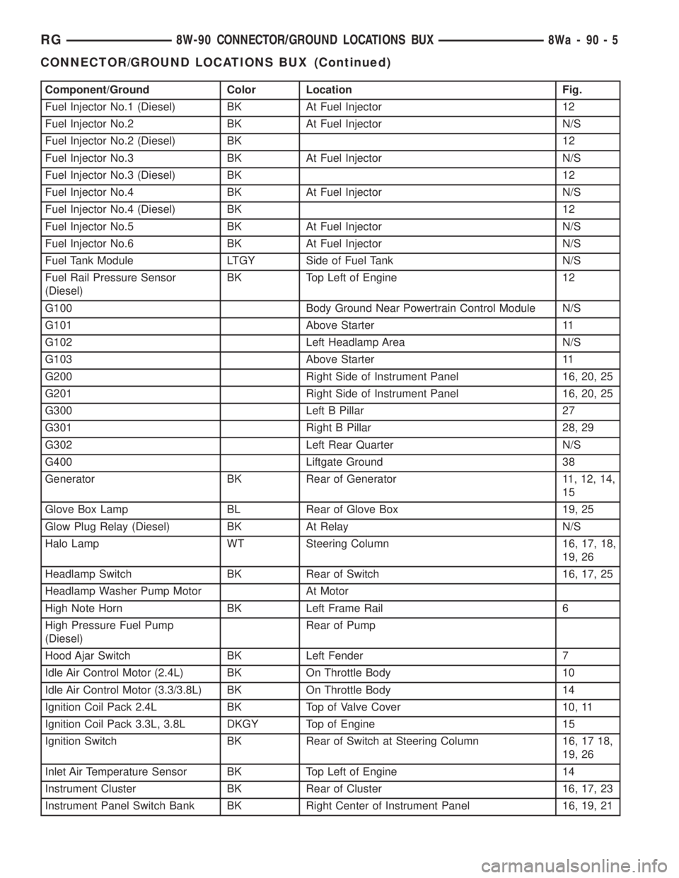
Fuel Injector No.1 (Diesel) BK At Fuel Injector 12
Fuel Injector No.2 BK At Fuel Injector N/S
Fuel Injector No.2 (Diesel) BK 12
Fuel Injector No.3 BK At Fuel Injector N/S
Fuel Injector No.3 (Diesel) BK 12
Fuel Injector No.4 BK At Fuel Injector N/S
Fuel Injector No.4 (Diesel) BK 12
Fuel Injector No.5 BK At Fuel Injector N/S
Fuel Injector No.6 BK At Fuel Injector N/S
Fuel Tank Module LTGY Side of Fuel Tank N/S
Fuel Rail Pressure Sensor
(Diesel)BK Top Left of Engine 12
G100 Body Ground Near Powertrain Control Module N/S
G101 Above Starter 11
G102 Left Headlamp Area N/S
G103 Above Starter 11
G200 Right Side of Instrument Panel 16, 20, 25
G201 Right Side of Instrument Panel 16, 20, 25
G300 Left B Pillar 27
G301 Right B Pillar 28, 29
G302 Left Rear Quarter N/S
G400 Liftgate Ground 38
Generator BK Rear of Generator 11, 12, 14,
15
Glove Box Lamp BL Rear of Glove Box 19, 25
Glow Plug Relay (Diesel) BK At Relay N/S
Halo Lamp WT Steering Column 16, 17, 18,
19, 26
Headlamp Switch BK Rear of Switch 16, 17, 25
Headlamp Washer Pump Motor At Motor
High Note Horn BK Left Frame Rail 6
High Pressure Fuel Pump
(Diesel)Rear of Pump
Hood Ajar Switch BK Left Fender 7
Idle Air Control Motor (2.4L) BK On Throttle Body 10
Idle Air Control Motor (3.3/3.8L) BK On Throttle Body 14
Ignition Coil Pack 2.4L BK Top of Valve Cover 10, 11
Ignition Coil Pack 3.3L, 3.8L DKGY Top of Engine 15
Ignition Switch BK Rear of Switch at Steering Column 16, 17 18,
19, 26
Inlet Air Temperature Sensor BK Top Left of Engine 14
Instrument Cluster BK Rear of Cluster 16, 17, 23
Instrument Panel Switch Bank BK Right Center of Instrument Panel 16, 19, 21
RG8W-90 CONNECTOR/GROUND LOCATIONS BUX8Wa-90-5
CONNECTOR/GROUND LOCATIONS BUX (Continued)
Page 2569 of 4284
Component/Ground Color Location Fig.
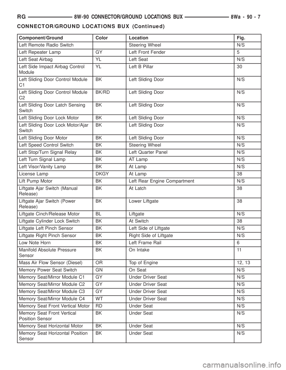
Left Remote Radio Switch Steering Wheel N/S
Left Repeater Lamp GY Left Front Fender 5
Left Seat Airbag YL Left Seat N/S
Left Side Impact Airbag Control
ModuleYL Left B Pillar 30
Left Sliding Door Control Module
C1BK Left Sliding Door N/S
Left Sliding Door Control Module
C2BK/RD Left Sliding Door N/S
Left Sliding Door Latch Sensing
SwitchBK Left Sliding Door N/S
Left Sliding Door Lock Motor BK Left Sliding Door N/S
Left Sliding Door Lock Motor/Ajar
SwitchBK Left Sliding Door N/S
Left Sliding Door Motor BK Left Sliding Door N/S
Left Speed Control Switch BK Steering Wheel N/S
Left Stop/Turn Signal Relay BK Left Quarter Panel N/S
Left Turn Signal Lamp BK AT Lamp N/S
Left Visor/Vanity Lamp BK At Lamp N/S
License Lamp DKGY At Lamp 38
Lift Pump Motor BK Left Rear Engine Compartment N/S
Liftgate Ajar Switch (Manual
Release)BK At Latch 38
Liftgate Ajar Switch (Power
Release)BK Lower Liftgate 38
Liftgate Cinch/Release Motor BL Liftgate N/S
Liftgate Cylinder Lock Switch BK At Switch 38
Liftgate Left Pinch Sensor BK Left Side of Liftgate N/S
Liftgate Right Pinch Sensor BK Right Side of Liftgate N/S
Low Note Horn BK Left Frame Rail 6
Manifold Absolute Pressure
SensorBK On Intake 11
Mass Air Flow Sensor (Diesel) OR Top of Engine 12, 13
Memory Power Seat Switch GN On Seat N/S
Memory Seat/Mirror Module C1 GY Under Driver Seat N/S
Memory Seat/Mirror Module C2 GY Under Driver Seat N/S
Memory Seat/Mirror Module C3 GY Under Driver Seat N/S
Memory Seat/Mirror Module C4 WT Under Driver Seat N/S
Memory Seat Front Vertical Motor RD Under Seat N/S
Memory Seat Front Vertical
Position SensorBK Under Seat N/S
Memory Seat Horizontal Motor BK Under Seat N/S
Memory Seat Horizontal Position
SensorBK Under Seat N/S
RG8W-90 CONNECTOR/GROUND LOCATIONS BUX8Wa-90-7
CONNECTOR/GROUND LOCATIONS BUX (Continued)
Page 2571 of 4284
Component/Ground Color Location Fig.
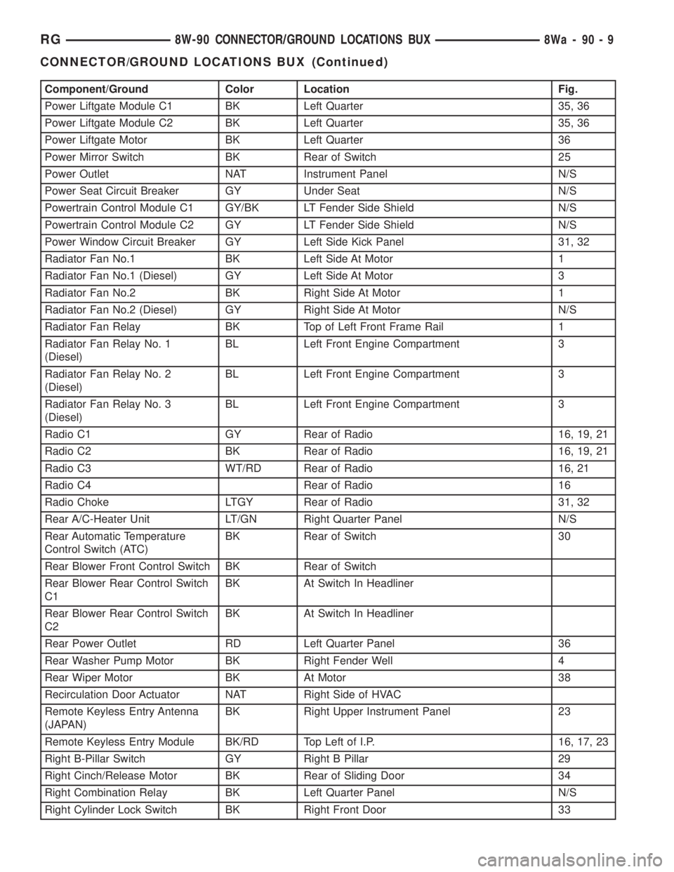
Power Liftgate Module C1 BK Left Quarter 35, 36
Power Liftgate Module C2 BK Left Quarter 35, 36
Power Liftgate Motor BK Left Quarter 36
Power Mirror Switch BK Rear of Switch 25
Power Outlet NAT Instrument Panel N/S
Power Seat Circuit Breaker GY Under Seat N/S
Powertrain Control Module C1 GY/BK LT Fender Side Shield N/S
Powertrain Control Module C2 GY LT Fender Side Shield N/S
Power Window Circuit Breaker GY Left Side Kick Panel 31, 32
Radiator Fan No.1 BK Left Side At Motor 1
Radiator Fan No.1 (Diesel) GY Left Side At Motor 3
Radiator Fan No.2 BK Right Side At Motor 1
Radiator Fan No.2 (Diesel) GY Right Side At Motor N/S
Radiator Fan Relay BK Top of Left Front Frame Rail 1
Radiator Fan Relay No. 1
(Diesel)BL Left Front Engine Compartment 3
Radiator Fan Relay No. 2
(Diesel)BL Left Front Engine Compartment 3
Radiator Fan Relay No. 3
(Diesel)BL Left Front Engine Compartment 3
Radio C1 GY Rear of Radio 16, 19, 21
Radio C2 BK Rear of Radio 16, 19, 21
Radio C3 WT/RD Rear of Radio 16, 21
Radio C4 Rear of Radio 16
Radio Choke LTGY Rear of Radio 31, 32
Rear A/C-Heater Unit LT/GN Right Quarter Panel N/S
Rear Automatic Temperature
Control Switch (ATC)BK Rear of Switch 30
Rear Blower Front Control Switch BK Rear of Switch
Rear Blower Rear Control Switch
C1BK At Switch In Headliner
Rear Blower Rear Control Switch
C2BK At Switch In Headliner
Rear Power Outlet RD Left Quarter Panel 36
Rear Washer Pump Motor BK Right Fender Well 4
Rear Wiper Motor BK At Motor 38
Recirculation Door Actuator NAT Right Side of HVAC
Remote Keyless Entry Antenna
(JAPAN)BK Right Upper Instrument Panel 23
Remote Keyless Entry Module BK/RD Top Left of I.P. 16, 17, 23
Right B-Pillar Switch GY Right B Pillar 29
Right Cinch/Release Motor BK Rear of Sliding Door 34
Right Combination Relay BK Left Quarter Panel N/S
Right Cylinder Lock Switch BK Right Front Door 33
RG8W-90 CONNECTOR/GROUND LOCATIONS BUX8Wa-90-9
CONNECTOR/GROUND LOCATIONS BUX (Continued)
Page 2637 of 4284
(24) Remove rear engine mount bracket. (Refer to
9 - ENGINE/ENGINE MOUNTING/REAR MOUNT -
REMOVAL)
(25) Mark flex plate to torque converter and
remove torque converter bolts.
(26) Pinch-off power steering supply hose at pump.
Remove hose from pump.
(27) Remove and set aside the power steering
pump and bracket. Do not disconnect pressure line.
(28) Lower vehicle.(29) Remove A/C lines at compressor and cap open-
ings.
(30) Remove engine ground straps (strap at engine
right mount and at starter).
(31) Raise vehicle enough to allow engine dolly
Special Tool 6135, cradle Special Tool 6710 with
Posts Special Tool 6848 to be installed under vehicle
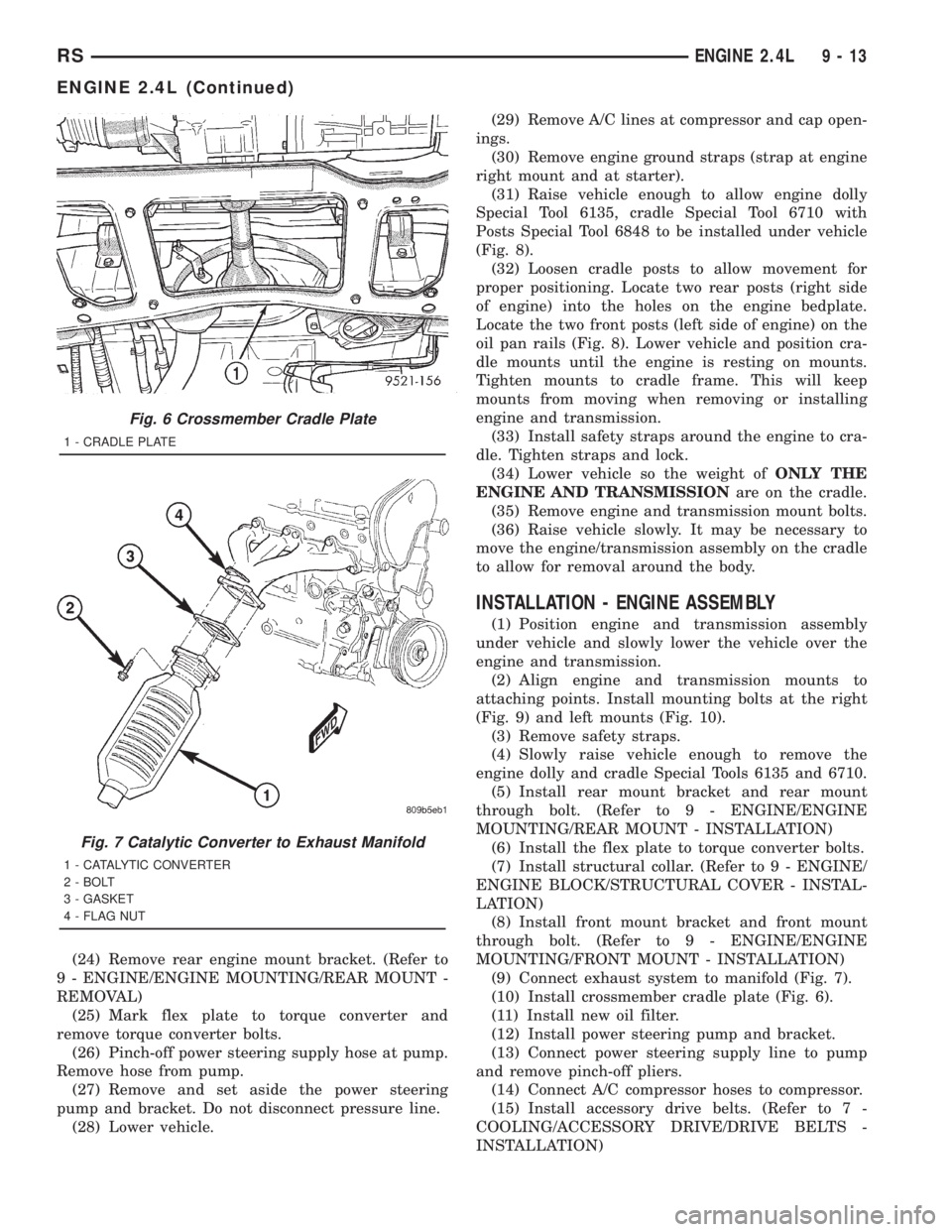
(Fig. 8).
(32) Loosen cradle posts to allow movement for
proper positioning. Locate two rear posts (right side
of engine) into the holes on the engine bedplate.
Locate the two front posts (left side of engine) on the
oil pan rails (Fig. 8). Lower vehicle and position cra-
dle mounts until the engine is resting on mounts.
Tighten mounts to cradle frame. This will keep
mounts from moving when removing or installing
engine and transmission.
(33) Install safety straps around the engine to cra-
dle. Tighten straps and lock.
(34) Lower vehicle so the weight ofONLY THE
ENGINE AND TRANSMISSIONare on the cradle.
(35) Remove engine and transmission mount bolts.
(36) Raise vehicle slowly. It may be necessary to
move the engine/transmission assembly on the cradle
to allow for removal around the body.
INSTALLATION - ENGINE ASSEMBLY
(1) Position engine and transmission assembly
under vehicle and slowly lower the vehicle over the
engine and transmission.
(2) Align engine and transmission mounts to
attaching points. Install mounting bolts at the right
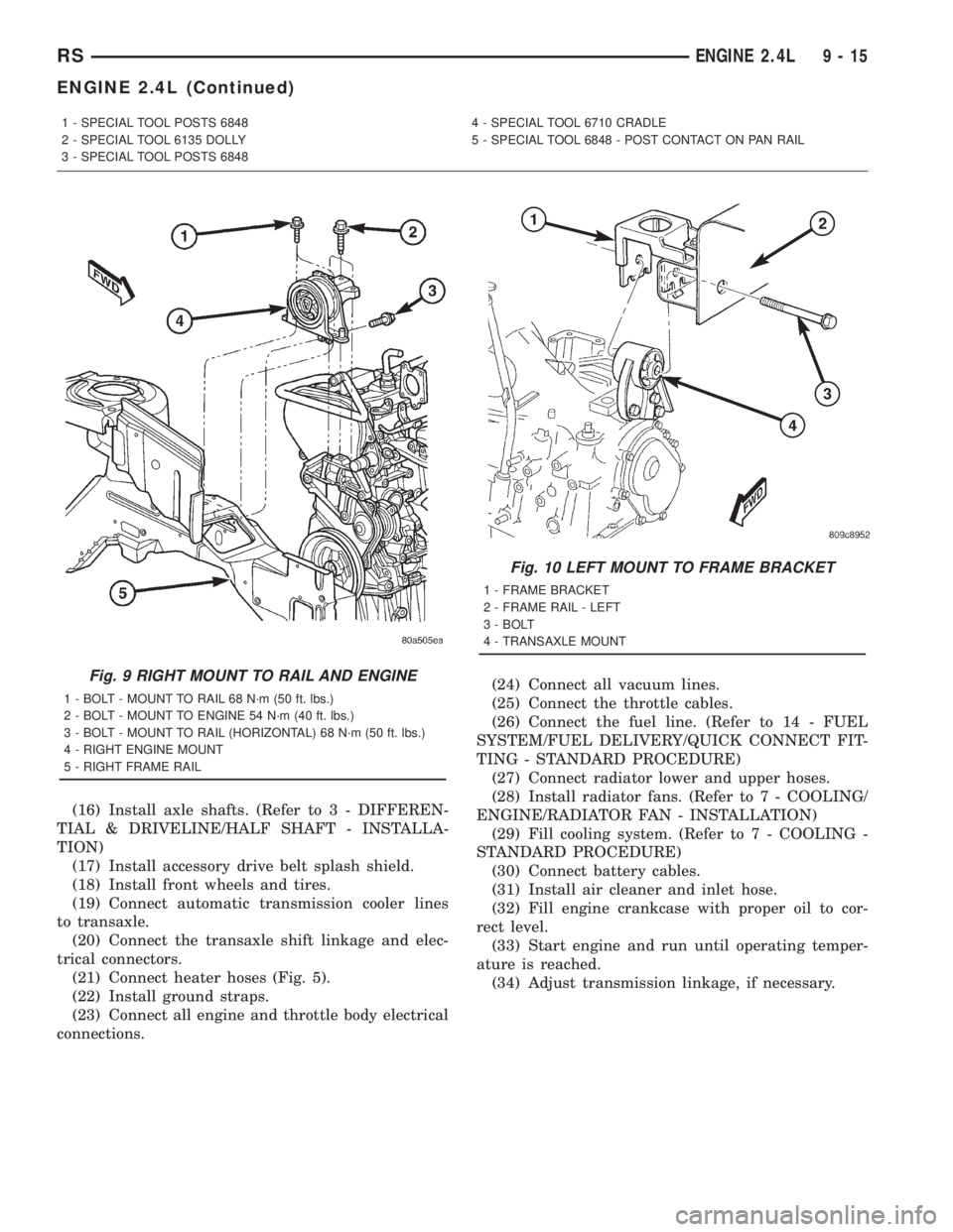
(Fig. 9) and left mounts (Fig. 10).
(3) Remove safety straps.
(4) Slowly raise vehicle enough to remove the
engine dolly and cradle Special Tools 6135 and 6710.
(5) Install rear mount bracket and rear mount
through bolt. (Refer to 9 - ENGINE/ENGINE
MOUNTING/REAR MOUNT - INSTALLATION)
(6) Install the flex plate to torque converter bolts.
(7) Install structural collar. (Refer to 9 - ENGINE/
ENGINE BLOCK/STRUCTURAL COVER - INSTAL-
LATION)
(8) Install front mount bracket and front mount
through bolt. (Refer to 9 - ENGINE/ENGINE
MOUNTING/FRONT MOUNT - INSTALLATION)
(9) Connect exhaust system to manifold (Fig. 7).
(10) Install crossmember cradle plate (Fig. 6).
(11) Install new oil filter.
(12) Install power steering pump and bracket.
(13) Connect power steering supply line to pump
and remove pinch-off pliers.
(14) Connect A/C compressor hoses to compressor.
(15) Install accessory drive belts. (Refer to 7 -
COOLING/ACCESSORY DRIVE/DRIVE BELTS -
INSTALLATION)
Fig. 6 Crossmember Cradle Plate
1 - CRADLE PLATE
Fig. 7 Catalytic Converter to Exhaust Manifold
1 - CATALYTIC CONVERTER
2 - BOLT
3 - GASKET
4 - FLAG NUT
RSENGINE 2.4L9-13
ENGINE 2.4L (Continued)
Page 2639 of 4284
(16) Install axle shafts. (Refer to 3 - DIFFEREN-
TIAL & DRIVELINE/HALF SHAFT - INSTALLA-
TION)
(17) Install accessory drive belt splash shield.
(18) Install front wheels and tires.
(19) Connect automatic transmission cooler lines
to transaxle.
(20) Connect the transaxle shift linkage and elec-
trical connectors.
(21) Connect heater hoses (Fig. 5).
(22) Install ground straps.
(23) Connect all engine and throttle body electrical
connections.(24) Connect all vacuum lines.
(25) Connect the throttle cables.
(26) Connect the fuel line. (Refer to 14 - FUEL
SYSTEM/FUEL DELIVERY/QUICK CONNECT FIT-
TING - STANDARD PROCEDURE)
(27) Connect radiator lower and upper hoses.
(28) Install radiator fans. (Refer to 7 - COOLING/
ENGINE/RADIATOR FAN - INSTALLATION)
(29) Fill cooling system. (Refer to 7 - COOLING -
STANDARD PROCEDURE)
(30) Connect battery cables.
(31) Install air cleaner and inlet hose.
(32) Fill engine crankcase with proper oil to cor-
rect level.
(33) Start engine and run until operating temper-
ature is reached.
(34) Adjust transmission linkage, if necessary.
1 - SPECIAL TOOL POSTS 6848 4 - SPECIAL TOOL 6710 CRADLE
2 - SPECIAL TOOL 6135 DOLLY 5 - SPECIAL TOOL 6848 - POST CONTACT ON PAN RAIL
3 - SPECIAL TOOL POSTS 6848
Fig. 9 RIGHT MOUNT TO RAIL AND ENGINE
1 - BOLT - MOUNT TO RAIL 68 N´m (50 ft. lbs.)
2 - BOLT - MOUNT TO ENGINE 54 N´m (40 ft. lbs.)
3 - BOLT - MOUNT TO RAIL (HORIZONTAL) 68 N´m (50 ft. lbs.)
4 - RIGHT ENGINE MOUNT
5 - RIGHT FRAME RAIL
Fig. 10 LEFT MOUNT TO FRAME BRACKET
1 - FRAME BRACKET
2 - FRAME RAIL - LEFT
3 - BOLT
4 - TRANSAXLE MOUNT
RSENGINE 2.4L9-15
ENGINE 2.4L (Continued)
Page 2671 of 4284
²Step 3: Final torque collar to transaxle bolts to
101 N´m (75 ft. lbs.)
²Step 4: Final torque collar to oil pan bolts to 54
N´m (40 ft. lbs.).
(2) Install engine front mount bracket and insula-
tor. (Refer to 9 - ENGINE/ENGINE MOUNTING/
FRONT MOUNT - INSTALLATION)
(3) Lower vehicle.
ENGINE MOUNTING
DESCRIPTION
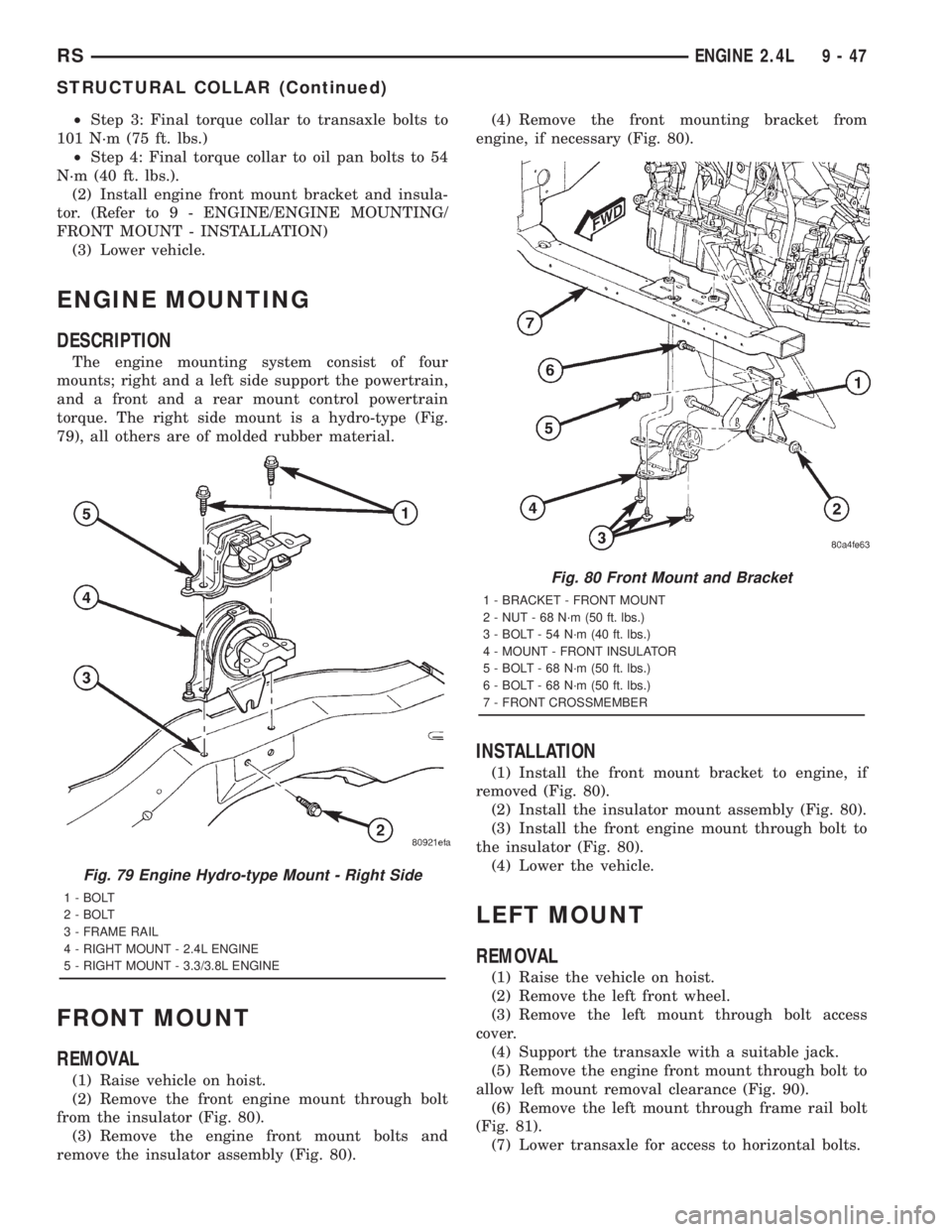
The engine mounting system consist of four
mounts; right and a left side support the powertrain,
and a front and a rear mount control powertrain
torque. The right side mount is a hydro-type (Fig.
79), all others are of molded rubber material.
FRONT MOUNT
REMOVAL
(1) Raise vehicle on hoist.
(2) Remove the front engine mount through bolt
from the insulator (Fig. 80).
(3) Remove the engine front mount bolts and
remove the insulator assembly (Fig. 80).(4) Remove the front mounting bracket from
engine, if necessary (Fig. 80).
INSTALLATION
(1) Install the front mount bracket to engine, if
removed (Fig. 80).
(2) Install the insulator mount assembly (Fig. 80).
(3) Install the front engine mount through bolt to
the insulator (Fig. 80).
(4) Lower the vehicle.
LEFT MOUNT
REMOVAL
(1) Raise the vehicle on hoist.
(2) Remove the left front wheel.
(3) Remove the left mount through bolt access
cover.
(4) Support the transaxle with a suitable jack.
(5) Remove the engine front mount through bolt to
allow left mount removal clearance (Fig. 90).
(6) Remove the left mount through frame rail bolt
(Fig. 81).
(7) Lower transaxle for access to horizontal bolts.
Fig. 79 Engine Hydro-type Mount - Right Side
1 - BOLT
2 - BOLT
3 - FRAME RAIL
4 - RIGHT MOUNT - 2.4L ENGINE
5 - RIGHT MOUNT - 3.3/3.8L ENGINE
Fig. 80 Front Mount and Bracket
1 - BRACKET - FRONT MOUNT
2 - NUT - 68 N´m (50 ft. lbs.)
3 - BOLT - 54 N´m (40 ft. lbs.)
4 - MOUNT - FRONT INSULATOR
5 - BOLT - 68 N´m (50 ft. lbs.)
6 - BOLT - 68 N´m (50 ft. lbs.)
7 - FRONT CROSSMEMBER
RSENGINE 2.4L9-47
STRUCTURAL COLLAR (Continued)
Page 2672 of 4284
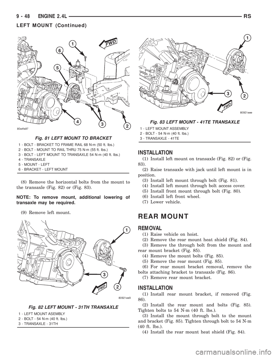
(8) Remove the horizontal bolts from the mount to
the transaxle (Fig. 82) or (Fig. 83).
NOTE: To remove mount, additional lowering of
transaxle may be required.
(9) Remove left mount.
INSTALLATION
(1) Install left mount on transaxle (Fig. 82) or (Fig.
83).
(2) Raise transaxle with jack until left mount is in
position.
(3) Install left mount through bolt (Fig. 81).
(4) Install left mount through bolt access cover.
(5) Install front mount through bolt (Fig. 80).
(6) Install left front wheel.
(7) Lower vehicle.
REAR MOUNT
REMOVAL
(1) Raise vehicle on hoist.
(2) Remove the rear mount heat shield (Fig. 84).
(3) Remove the through bolt from the mount and
rear mount bracket (Fig. 85).
(4) Remove the mount bolts (Fig. 85).
(5) Remove the rear mount (Fig. 85).
(6) For rear mount bracket removal, remove the
bolts attaching bracket to transaxle (Fig. 86).
(7) Remove rear mount bracket.
INSTALLATION
(1) Install rear mount bracket, if removed (Fig.
86).
(2) Install the rear mount and bolts (Fig. 85).
Tighten bolts to 54 N´m (40 ft. lbs.).
(3) Install the mount through bolt to the mount
and bracket (Fig. 85). Tighten through bolt to 54 N´m
(40 ft. lbs.).
(4) Install the rear mount heat shield (Fig. 84).
Fig. 81 LEFT MOUNT TO BRACKET
1 - BOLT - BRACKET TO FRAME RAIL 68 N´m (50 ft. lbs.)
2 - BOLT - MOUNT TO RAIL THRU 75 N´m (55 ft. lbs.)
3 - BOLT - LEFT MOUNT TO TRANSAXLE 54 N´m (40 ft. lbs.)
4 - TRANSAXLE
5 - MOUNT - LEFT
6 - BRACKET - LEFT MOUNT
Fig. 82 LEFT MOUNT - 31TH TRANSAXLE
1 - LEFT MOUNT ASEMBLY
2 - BOLT - 54 N´m (40 ft. lbs.)
3 - TRANSAXLE - 31TH
Fig. 83 LEFT MOUNT - 41TE TRANSAXLE
1 - LEFT MOUNT ASSEMBLY
2 - BOLT - 54 N´m (40 ft. lbs.)
3 - TRANSAXLE - 41TE
9 - 48 ENGINE 2.4LRS
LEFT MOUNT (Continued)
Page 2674 of 4284
RIGHT MOUNT
REMOVAL
(1) Remove air cleaner housing lid and clean air
hose from throttle body.
(2) Remove air cleaner element and housing.
(3) Disconnect make-up air hose from cylinder
head cover.
(4) Remove the load on the right engine mount by
carefully supporting the engine assembly with a floor
jack.
(5) Disconnect electrical harness support clips from
engine mount bracket.
(6) Remove the vertical bolts attaching the engine
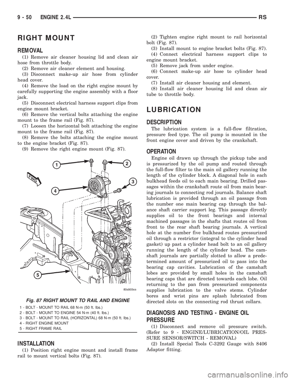
mount to the frame rail (Fig. 87).
(7) Loosen the horizontal bolt attaching the engine
mount to the frame rail (Fig. 87).
(8) Remove the bolts attaching the engine mount
to the engine bracket (Fig. 87).
(9) Remove the right engine mount (Fig. 87).
INSTALLATION
(1) Position right engine mount and install frame
rail to mount vertical bolts (Fig. 87).(2) Tighten engine right mount to rail horizontal
bolt (Fig. 87).
(3) Install mount to engine bracket bolts (Fig. 87).
(4) Connect electrical harness support clips to
engine mount bracket.
(5) Remove jack from under engine.
(6) Connect make-up air hose to cylinder head
cover.
(7) Install air cleaner housing and element.
(8) Install air cleaner housing lid and clean air
tube to throttle body.
LUBRICATION
DESCRIPTION
The lubrication system is a full-flow filtration,
pressure feed type. The oil pump is mounted in the
front engine cover and driven by the crankshaft.
OPERATION
Engine oil drawn up through the pickup tube and
is pressurized by the oil pump and routed through
the full-flow filter to the main oil gallery running the
length of the cylinder block. A diagonal hole in each
bulkhead feeds oil to each main bearing. Drilled pas-
sages within the crankshaft route oil from main bear-
ing journals to connecting rod journals. Balance shaft
lubrication is provided through an oil passage from
the number one main bearing cap through the bal-
ance shaft carrier support leg. This passage directly
supplies oil to the front bearings and internal
machined passages in the shafts that routes oil from
front to the rear shaft bearing journals. A vertical
hole at the number five bulkhead routes pressurized
oil through a restrictor (integral to the cylinder head
gasket) up past a cylinder head bolt to an oil gallery
running the length of the cylinder head. The cam-
shaft journals are partially slotted to allow a prede-
termined amount of pressurized oil to pass into the
bearing cap cavities. Lubrication of the camshaft
lobes are provided by small holes in the camshaft
bearing caps that are directed towards each lobe. Oil
returning to the pan from pressurized components
supplies lubrication to the valve stems. Cylinder
bores and wrist pins are splash lubricated from
directed slots on the connecting rod thrust collars.
DIAGNOSIS AND TESTING - ENGINE OIL
PRESSURE
(1) Disconnect and remove oil pressure switch.
(Refer to 9 - ENGINE/LUBRICATION/OIL PRES-
SURE SENSOR/SWITCH - REMOVAL)
(2) Install Special Tools C-3292 Gauge with 8406
Adaptor fitting.
Fig. 87 RIGHT MOUNT TO RAIL AND ENGINE
1 - BOLT - MOUNT TO RAIL 68 N´m (50 ft. lbs.)
2 - BOLT - MOUNT TO ENGINE 54 N´m (40 ft. lbs.)
3 - BOLT - MOUNT TO RAIL (HORIZONTAL) 68 N´m (50 ft. lbs.)
4 - RIGHT ENGINE MOUNT
5 - RIGHT FRAME RAIL
9 - 50 ENGINE 2.4LRS