2001 CHRYSLER VOYAGER change wheel
[x] Cancel search: change wheelPage 33 of 4284
Ifneither of the following codes is an active code:
ACTIVE DTC SQUIB STATUS
Driver squib 1 open Status of Airbag is
Driver Squib 2 open Unknown.
3.1.2 CLOCKSPRING
The clockspring is mounted on the steering col-
umn behind the steering wheel. This assembly
consist of a plastic housing which contains a flat,
ribbon-like, electrically conductive tape that winds
and unwinds with the steering wheel rotation. The
clockspring is used to maintain a continuous elec-
trical circuit between the instrument panel wiring
and the driver airbag, the horn, and the vehicle
speed control switches if equipped. The clockspring
must be properly centered when it is reinstalled on
the steering column following any service proce-
dure, or it could be damaged. The clockspring can-
not be repaired and it must be replaced.
3.1.3 PASSENGER AIRBAG
The airbag door in the instrument panel top cover
the glove box is the most visible part of the passen-
ger side airbag system. The airbag door has a living
hinge at the top, which is secured to the instrument
panel top cover. Located under the airbag door is
the airbag cushion and its supporting components.
The airbag module includes a housing to which the
cushion and hybrid inflators are attached and
sealed. The 2001 Minivan is equipped with front
passenger airbag with dual stage inflators that
include a small canister of highly compressed argon
gas. The ORC uses vehicle crash severity, front
passenger seat belt switch status (buckled or un-
buckled) inputs to determine the level of airbag
deployment. When supplied with the proper electri-
cal signal, the hybrid inflator or inflators discharge
the compressed gas it contains directly into the
cushion. The airbag module cannot be repaired, and
must be replaced if deployed or in any way dam-
aged.
WARNING: THE PASSENGER AIRBAG
MODULE CONTAINS ARGON GAS
PRESSURIZED TO 17236.89 Kpa (2500 PSI).
DO NOT ATTEMPT TO DISMANTLE AN
AIRBAG MODULE OR TAMPER WITH ITS
INFLATOR. DO NOT PUNCTURE,
INCINERATE, OR BRING INTO CONTACT
WITH ELECTRICITY. DO NOT STORE AT
TEMPERATURE EXCEEDING 93ÉC (200ÉF).
REPLACE AIRBAG SYSTEM COMPONENTS
ONLY WITH PARTS SPECIFIED IN THE
MOPAR PARTS CATALOG. SUBSTITUTE
PARTS MAY APPEAR INTERCHANGEABLE,
BUT INTERNAL DIFFERENCES MAY RESULT
IN INFERIOR OCCUPANT PROTECTION. THE
FASTENERS, SCREWS, AND BOLTS
ORIGINALLY USED FOR THE AIRBAG
SYSTEM COMPONENTS HAVE SPECIAL
COATINGS AND ARE SPECIFICALLY
DESIGNED FOR THE AIRBAG SYSTEM. THEY
MUST NEVER BE REPLACED WITH ANY
SUBSTITUTES. ANY TIME A NEW FASTENER
IS NEEDED, REPLACE IT WITH THE
CORRECT FASTENERS PROVIDED IN THE
SERVICE PACKAGE OR SPECIFIED IN THE
MOPAR PARTS CATALOG.
4
GENERAL INFORMATION
Page 35 of 4284
if the system is functioning properly. If the test
finds a problem the SIACM will set both active and
stored diagnostic trouble codes. If a DTC is active
the SIACM will request that the airbag warning
lamp be turned on. The results of the system test
are transmitted on the PCI Bus to the ORC once
each second or on change in lamp state. If the
warning lamp status message from the either SI-
ACM contains a lamp on request, the ORC will set
an active DTC. At the same time as the DTC is set
the ORC sends a PCI Bus message to the mechan-
ical instrument cluster (MIC) requesting the airbag
warning lamp be turned on. Observe all ORC warn-
ing and caution statements when servicing or han-
dling the SIACM. SIACM are not repairable and
must be replaced if they are dropped.
WARNING: THE AIRBAG SYSTEM IS A
SENSITIVE, COMPLEX ELECTRO-
MECHANICAL UNIT. BEFORE ATTEMPTING
TO DIAGNOSE OR SERVICE ANY AIRBAG
SYSTEM OR RELATED STEERING WHEEL,
STEERING COLUMN, OR INSTRUMENT
PANEL COMPONENTS YOU MUST FIRST
DISCONNECT AND ISOLATE THE BATTERY
NEGATIVE (GROUND) CABLE. WAIT TWO
MINUTES FOR THE SYSTEM CAPACITOR TO
DISCHARGE BEFORE FURTHER SYSTEM
SERVICE. THIS IS THE ONLY SURE WAY TO
DISABLE THE AIRBAG SYSTEM. FAILURE
TO DO THIS COULD RESULT IN ACCIDENTAL
AIRBAG DEPLOYMENT AND POSSIBLE
PERSONAL INJURY. NEVER STRIKE OR
KICK THE AIRBAG CONTROL MODULE, AS
IT CAN DAMAGE THE IMPACT SENSOR OR
AFFECT ITS CALIBRATION. IF AN AIRBAG
CONTROL MODULE IS ACCIDENTALLY
DROPPED DURING SERVICE, THE MODULE
MUST BE SCRAPPED AND REPLACED WITH
A NEW UNIT.
The airbag warning lamp is the only point at
which the customer can observe symptoms of a
system malfunction. Whenever the ignition key is
turned to the run or start position, the MIC per-
forms a lamp check by turning the airbag warning
indicator on for 6-8 seconds. After the lamp check, if
the indicator turns on, it means that the ORC has
checked the system and found it to be free of
discernible malfuctions. If the lamp remains on,
there could be an active fault in the system or the
MIC lamp circuit may be internally shorted to
ground. If the lamp comes on and stays on for a
period longer than 6-8 seconds then goes off, there
is usually an intermittent problem in the system.
3.1.7 SEAT AIRBAGS (SAB)
The left and right seat airbag modules are located
in the outboard end of the front seat backs. The
airbag module contains a bag, an inflator (a small
canister of highly compressed argon gas) and a
mounting bracket. The seat airbag module cannot
be repaired and must be replaced if deployed or in
any way damaged. When supplied with the proper
electrical signal the inflator seals the hole in the
airbag cushion so it can discharge the compressed
gas it contains directly into the cushion. Upon
deployment, the seat back trim cover will tear open
and allow the seat airbag to fully deploy between
the seat and the door.
WARNING: SEAT AIRBAG CONTAINS ARGON
GAS PRESSURIZED TO OVER 17236.89 Kpa
(2500 PSI). DO NOT ATTEMPT TO
DISMANTLE AN AIRBAG MODULE OR
TAMPER WITH ITS INFLATOR. DO NOT
PUNCTURE, INCINERATE, OR BRING INTO
CONTACT WITH ELECTRICITY. DO NOT
STORE AT TEMPERATURE EXCEEDING 93ÉC
(200ÉF). REPLACE AIRBAG SYSTEM
COMPONENTS ONLY WITH PARTS
SPECIFIED IN THE CHRYSLER MOPAR
PARTS CATALOG. SUBSTITUTE PARTS MAY
APPEAR INTERCHANGEABLE, BUT
INTERNAL DIFFERENCES MAY RESULT IN
INFERIOR OCCUPANT PROTECTION. THE
FASTENERS, SCREWS, AND BOLTS
ORIGINALLY USED FOR THE AIRBAG
SYSTEM COMPONENTS HAVE SPECIAL
COATINGS AND ARE SPECIFICALLY
DESIGNED FOR THE AIRBAG SYSTEM. THEY
MUST NEVER BE REPLACED WITH ANY
SUBSTITUTES. ANY TIME A NEW FASTENER
IS NEEDED, REPLACE IT WITH THE
CORRECT FASTENERS PROVIDED IN THE
SERVICE PACKAGE OR SPECIFIED IN THE
MOPAR PARTS CATALOG.
3.1.8 ORC/SIACM DIAGNOSTIC TROUBLE
CODES
Airbag diagnostic trouble codes consist of active
and stored codes. If more than one code exists,
diagnostic priority should be given to the active
codes. Each diagnostic trouble code is diagnosed by
following a specific testing procedure. The diagnos-
tic test procedures contain step-by-step instructions
for determining the cause of the trouble codes. It is
not necessary to perform all of the tests in this book
to diagnose an individual code. Always begin by
reading the diagnostic trouble codes using the DRB.
Always begin diagnostic with the Table of Contents
6
GENERAL INFORMATION
Page 36 of 4284
section 7.0. This will direct you to the specific test(s)
that must be performed. Active diagnostic trouble
codes for the airbag system are not permanent and
will change the moment the reason for the code is
corrected. In certain test procedures within this
manual, diagnostic trouble codes are used as a
diagnostic tool.
3.1.9 ACTIVE CODES
The code becomes active as soon as the malfunc-
tion is detected or key-on, whichever occurs first. An
active trouble code indicates an on-going malfunc-
tion. This means that the defect is currently there
every time the airbag control module checks that
circuit or component. It is impossible to erase an
active code. Active codes automatically erase by
themselves when the reason for the code has been
corrected. With the exception of the warning lamp
trouble codes or malfunctions, when a malfunction
is detected, the airbag lamp remains lit for a mini-
mum of 12 seconds or as long as the malfunction is
present.
3.1.10 STORED CODES
Airbag codes are automatically stored in the
ORC's memory as soon as the malfunction is de-
tected. The exception is the Loss of Ignition Run
Only code which is an active code only. A stored code
indicates there was an active code present at some
time. However, the code currently may not be
present as an active code, although another code
could be active. When a trouble code occurs, the
airbag warning indicator illuminates for 12 seconds
minimum (even if the problem existed for less than
12 seconds). The code is stored, along with the time
in minutes it was active, and the number of times
the ignition has been cycled since the problem was
last detected. The minimum time shown for any
code will be one minute, even if the code was
actually present for less than one minute. Thus, the
time shown for a code will be one minute, even if the
code was actually present for less than one minute.
Thus, the time shown for a code that was present
for two minutes 13 seconds, for example, would be
three minutes. If a malfunction is detected a diag-
nostic trouble code is stored and will remain stored.
When and if the malfunction ceases to exist, an
ignition cycle count will be initiated for that code. If
the ignition cycle count reaches 100 without a
reoccurrence of the same malfunction, the diagnos-
tic trouble code is erased and that ignition cycle
counter is reset to zero. If the malfunction reoccurs
before the count reaches 100, then the ignition cycle
counter will be reset and diagnostic trouble code
will continue to be a stored code. If a malfunction is
not active while performing a diagnostic test proce-
dure, the active code diagnostic test will not locatethe source of the problem. In this case, the stored
code can indicate an area to inspect. If no obvious
problems are found, erase stored codes, and with
the ignition on wiggle the wire harness and connec-
tors, rotate the steering wheel from stop to stop.
Recheck for codes periodically as you work through
the system. This procedure may uncover a malfunc-
tion that is difficult to locate.
3.2 AUDIO SYSTEM
The following radios are all on the PCI Bus
system - RBB, RBK, RAZ, RAD, RBT, and RBY. The
remaining radio also available, the RAS, is NOT on
the PCI Bus. The PCI Bus inputs into the radio are
used for VF dimming, remote steering wheel con-
trols and cabin EQ preference. PCI Bus outputs
from the radio are used for the Name Brand
Speaker (NBS) relay activation, as well as cabin EQ
preference.
The RBB and RBK radios have the capability of
containing multiple vehicle unique equalization
curves (cabin EQ preferences) within the radio.
These curves will reside in the radio's flash memory.
The radio is capable of storing up to 20 unique
equalization curves. The latent curves can be se-
lected via the Front Control Module transmitting a
PCI Bus message to the radio in response to a radio
request for equalization message. Upon receipt of a
valid equalization select message response, the ra-
dio will switch to output the corresponding equal-
ization curve.
All the radios, except the RAS, are capable of
displaying faults and allowing certain actuation
tests through the use of the DRBIIIt. When at-
tempting to perform PCI Bus diagnostics, the first
step is to identify the radio in use in the vehicle.
When trouble shooting output shorts or ªoutputº
error messages, the following applies:
On radios without an external amplifier, the term
output refers to the path between the radio and the
speaker. This type of circuit can be monitored all
the way through the speaker connections by the
radio assembly. When the radio displays a shorted
output DTC with this type of system, the speaker,
radio, or wiring could be at fault. The output DTC
could refer to the front or rear output or a left or
right output. The reason for the difference is the
pairing of the output sections of the radio. Some are
paired left and right, others are paired front and
rear.
On radios with an external amplifier, the term
ªoutputº refers to the circuit between the radio
connector and the amplifier. The radio is capable of
monitoring only this portion and can tell nothing
about the circuit between the amplifier and the
speakers. Consequently, a shorted output DTC on
7
GENERAL INFORMATION
Page 37 of 4284
this type of system would only refer to this circuit.
A faulty speaker could not cause this DTC.
3.2.1 REMOTE RADIO CONTROLS
These radios can be controlled via remote radio
switches (optional). These switches are located on
the back side of the steering wheel. They control
mode, preset, seek up, seek down, volume up and
volume down functions.
These functions are inputs to the Body Control
Module and can be read with the DRBIIItunder
ªbody computerº. The switches are a multiplexed
signal to the BCM. The radio control MUX circuit is
a 5 volt line that is pulled to ground through
different value resistors built into the switches.
This causes a voltage drop to be seen by the BCM
and it sends a specific message to the radio on the
PCI Bus circuit. The radio then responses to the
message.
This circuit is fairly simple to troubleshoot. The
circuit must be complete from the switches in the
steering wheel to the BCM. The ground must be
complete so that the switches can cause the voltage
drop for the BCM to see. The circuit passes through
the clockspring so continuity through this devise
must be verified.
3.2.2 CD CHANGER
The new in-dash CD Changer is designed to fit
into the existing cubby bin in the center stack. This
new cartridge-less CD Changer is controlled by
your radio, and allows you to individually load up to
four discs at a time. However, due to its compact
design, the CD Changer can only carry out one
operation at a time. For example, you can not load
a new disc while playing another at the same time.
Each operation happens sequentially.
The radio unit installed with your system pro-
vides control over all features of the CD Changer
with the exception of the CD load and eject func-
tions, which are controlled by buttons located on the
front of the CD Changer. The radio also supplies the
power, ground, PCI Bus, left and right speaker
output thru a single DIN cable. All features you
would expect, such as Disc Up/Down, Track Up/
Down, Random and Scan are controlled by the
radio, which also displays all relevant CD Changer
information on the radio display.
The CD Changer contains a Load/Eject button
and an indicator light for each of the four disc
positions. The individual light indicates whether a
CD is currently loaded in that particular chamber of
the CD Changer. Pressing the individual Load/Eject
button for a particular chamber will eject a disc
currently present in that chamber. If the chamber iscurrently empty, actuating the Load/Eject button
will position that chamber to receive and load a new
disc in that chamber.
3.3 BODY CONTROL MODULE
The body control module (BCM) supplies vehicle
occupants with visual and audible information and
controls various vehicle functions. To provide and
receive information, the module is interfaced to the
vehicle's serial bus communications network (PCI).
This network consists of the powertrain control
module (PCM), the engine control module (ECM) -
diesel only, the transmission control module (TCM),
the mechanical instrument cluster (MIC), the front
control module (FCM), the occupant restraint con-
troller (ORC), the compass/mini-trip (CMTC), the
electronic vehicle information center (EVIC), the
controller antilock brake (CAB), the HVAC control
module (ATC & MTC), the power sliding door (Left
& Right) modules (PSD), the power liftgate module
(PLG), the Audio system, the side impact airbag
control (left & right) modules (SIACM), the memory
seat/mirror module (MSMM), the RKE/thatcham
alarm module and the sentry key immobilizer mod-
ule (SKIM). The BCM is operational when battery
power is supplied to the module.
The body control module provides the following
features:
²Power Door Locks
²Automatic Door Lock
²Door Lock Inhibit
²Central Locking (with VTSS Only)
²Battery Protection
²The BCM will automatically turn off all exterior
lamps after 3 minutes and all interior lamps after
15 minutes after the ignition is turned off, if they
are not turned off by the driver.
²Chime
²Compass/Minitrip Support
²Interior Lighting (Courtesy/Reading Lamps)
²BCM Diagnostic Reporting
²Electronic Liftgate Release (with Power Door
Locks)
²Exterior Lighting
²Power Folding Mirrors
²Remote Radio Controls
²Headlamp Time Delay (with/without Autohead-
lamps)
²Automatic Headlamps (with electrochromatic
mirror)
²Illuminated Entry
²Fade to Off
8
GENERAL INFORMATION
Page 57 of 4284
defined as the amount of time from the start of a
wipe to the beginning of the next wipe. The rear
wiper system delay time is based on the following:
7.75 - (MPH x .05) = Seconds delay
Examples:
At zero (0) MPH the delay is 7.75 seconds.
At 100 MPH the delay is 2.75 seconds.
3.21.8 WIPE AFTER WASH
When the driver presses the wash button for over
1.5 seconds and releases it, the wiper will continue
to run for 2 additional wipe cycles.
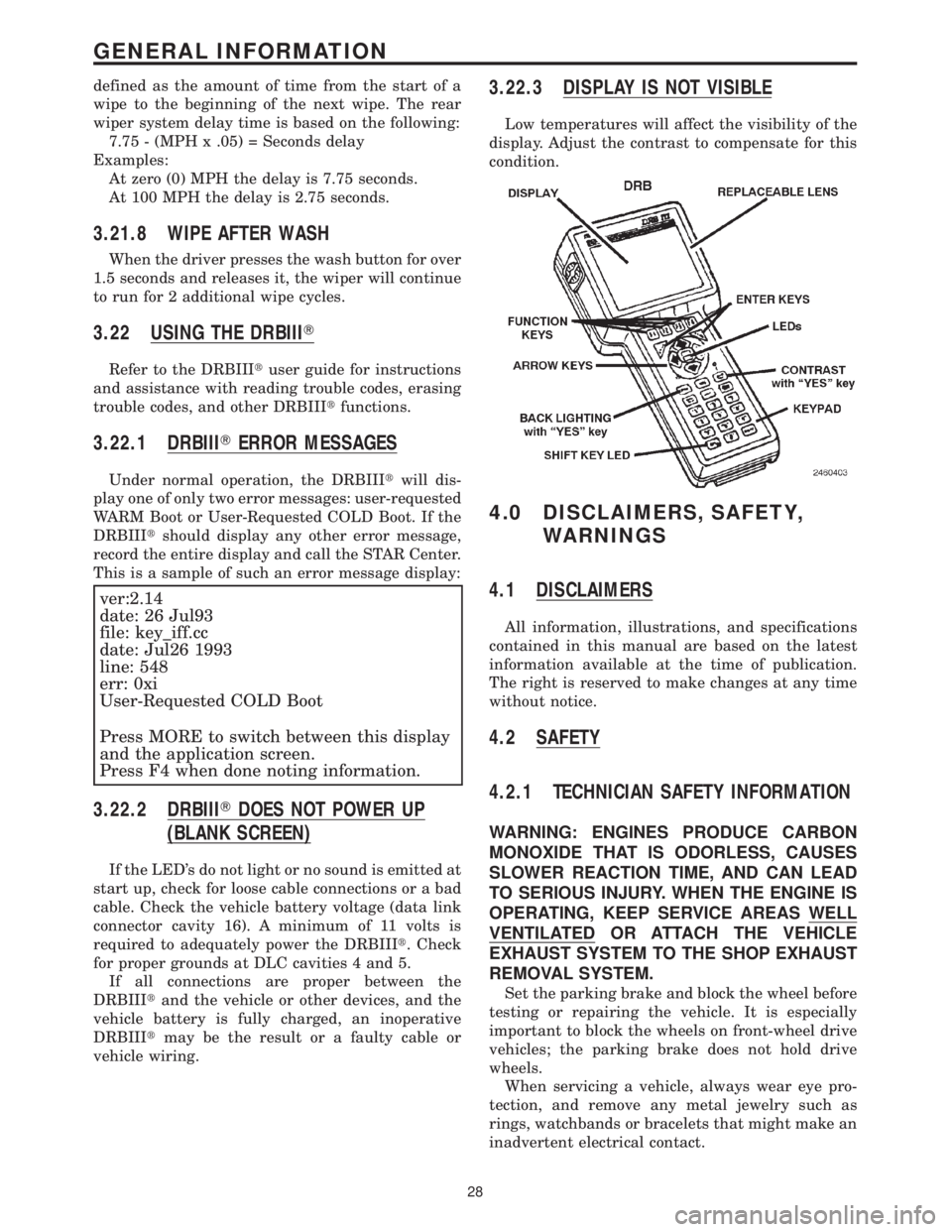
3.22 USING THE DRBIIIT
Refer to the DRBIIItuser guide for instructions
and assistance with reading trouble codes, erasing
trouble codes, and other DRBIIItfunctions.
3.22.1 DRBIIITERROR MESSAGES
Under normal operation, the DRBIIItwill dis-
play one of only two error messages: user-requested
WARM Boot or User-Requested COLD Boot. If the
DRBIIItshould display any other error message,
record the entire display and call the STAR Center.
This is a sample of such an error message display:
ver:2.14
date: 26 Jul93
file: key_iff.cc
date: Jul26 1993
line: 548
err: 0xi
User-Requested COLD Boot
Press MORE to switch between this display
and the application screen.
Press F4 when done noting information.
3.22.2 DRBIIITDOES NOT POWER UP
(BLANK SCREEN)
If the LED's do not light or no sound is emitted at
start up, check for loose cable connections or a bad
cable. Check the vehicle battery voltage (data link
connector cavity 16). A minimum of 11 volts is
required to adequately power the DRBIIIt. Check
for proper grounds at DLC cavities 4 and 5.
If all connections are proper between the
DRBIIItand the vehicle or other devices, and the
vehicle battery is fully charged, an inoperative
DRBIIItmay be the result or a faulty cable or
vehicle wiring.
3.22.3 DISPLAY IS NOT VISIBLE
Low temperatures will affect the visibility of the
display. Adjust the contrast to compensate for this
condition.
4.0 DISCLAIMERS, SAFETY,
WARNINGS
4.1 DISCLAIMERS
All information, illustrations, and specifications
contained in this manual are based on the latest
information available at the time of publication.
The right is reserved to make changes at any time
without notice.
4.2 SAFETY
4.2.1 TECHNICIAN SAFETY INFORMATION
WARNING: ENGINES PRODUCE CARBON
MONOXIDE THAT IS ODORLESS, CAUSES
SLOWER REACTION TIME, AND CAN LEAD
TO SERIOUS INJURY. WHEN THE ENGINE IS
OPERATING, KEEP SERVICE AREAS WELL
VENTILATED OR ATTACH THE VEHICLE
EXHAUST SYSTEM TO THE SHOP EXHAUST
REMOVAL SYSTEM.
Set the parking brake and block the wheel before
testing or repairing the vehicle. It is especially
important to block the wheels on front-wheel drive
vehicles; the parking brake does not hold drive
wheels.
When servicing a vehicle, always wear eye pro-
tection, and remove any metal jewelry such as
rings, watchbands or bracelets that might make an
inadvertent electrical contact.
28
GENERAL INFORMATION
Page 110 of 4284

ORC, WARNING INDICATOR CIRCUIT OPEN - STORED
When Monitored: When the ignition is On, the ORC monitors the PCI Bus for a message
from the MIC containing the airbag warning lamp status Ok or Open. The MIC transmits
the message one time at ignition on, upon lamp state change, or in response to the ORC
lamp message.
Set Condition: The code is set if the lamp state is open for 2 consecutive messages or 2
seconds.
ORC, WARNING INDICATOR CIRCUIT SHORT - STORED
When Monitored: When the ignition is On, the ORC monitors the PCI Bus for a message
from the MIC containing the airbag warning lamp status Ok or Shorted. The MIC
transmits the message one time at ignition on and upon lamp state change.
Set Condition: If the lamp state is Shorted for 2 consecutive messages the code will be set.
POSSIBLE CAUSES
CHECKING FOR ACTIVE ORC DTC'S
STORED CODE PRESENT
TEST ACTION APPLICABILITY
1 Turn ignition on.
NOTE: Ensure the battery is fully charged.
Active codes must be resolved before diagnosing stored codes.
With the DRBIIIt, record and erase all DTCs from all modules.
With the DRB III monitor active codes as you work through the system.
Wiggle the wiring harness and connectors of the Airbag System and rotate the
steering wheel from stop to stop.
NOTE: Check connectors - Clean and repair as necessary.
You have just attempted to simulate the condition that initially set the trouble code
message.
The following additional checks may assist you in identifying a possible intermittent
problem:
- Visually inspect related wire harness connectors. Look for broken, bent, pushed out,
spread, corroded, or contaminated terminals.
- Visually inspect related harnesses. Look for chafed, pierced, pinched or partially
broken wire.
- Refer to Wiring Diagrams and Technical Service Bulletins that may apply.
Did the DTC become active ?All
Ye s®Select appropriate symptom from Symptom List and continue
with diagnosis.
No®No problem found at this time. Erase codes in all modules before
returning vehicle to customer.
81
AIRBAG
ORC, CALIBRATION MISMATCH - STORED ÐContinued
Page 1158 of 4284
1.0 INTRODUCTION
The procedures contained in this manual include
all the specifications, instructions, and graphics
needed to diagnose Mark 20 Antilock Braking Sys-
tem (ABS) and Mark 20 Antilock Braking System
with Traction Control. The diagnostics in this man-
ual are based on the failure condition or symptom
being present at time of diagnosis.
Please follow the recommendations below when
choosing your diagnostic path.
1. First make sure the DRBIIItis communicating
with the CAB. If the DRBIIItdisplays a ªNo
Responseº condition, you must diagnose that
first.
2. Read DTC's (diagnostic trouble codes) with the
DRBIIIt.
3. If no DTC's are present, identify the customer
complaint.
4. Once the DTC or customer complaint is identi-
fied, locate the matching test in the Table of
Contents and begin to diagnose the symptom.
All component location views are in Section 8.0.
All connector pinouts are in Section 9.0. All sche-
matics are in Section 10.0.
An * placed before the symptom description indi-
cates a concern with no associated DTC.
When repairs are required, refer to the appropri-
ate service manual for the proper removal and
repair procedure.
Diagnostic procedures change every year. New
diagnostic systems may be added; carry over sys-
tems may be enhanced. READ THIS MANUAL
BEFORE TRYING TO DIAGNOSE A VEHICLE
CODE. It is recommended that you review the
entire manual to become familiar with all new and
changed diagnostic procedures.
After using this book, if you have any comments
or recommendations, please fill out the form at the
back of the book and mail it back to us.
1.1 SYSTEM COVERAGE
This diagnostic procedure manual covers the an-
tilock braking system (ABS) and traction control
system found on: 2001 Chrysler Town and Country,
Dodge Caravan and Grand Caravan.
1.2 SIX-STEP TROUBLESHOOTING
PROCEDURE
Diagnosis of the controller antilock brake module
is done in six basic steps:
²verification of complaint
²verification of any related symptoms
²symptom analysis
²problem isolation
²repair of isolated problem
²verification of proper operation
2.0 IDENTIFICATION OF
SYSTEM
Vehicles equipped with the Teves Mark 20 an-
tilock brake system can be identified by the pres-
ence of the controller antilock brake module located
beneath the master cylinder.
3.0 SYSTEM DESCRIPTION AND
FUNCTIONAL OPERATION
3.1 TEVES MARK 20 SYSTEM
DESCRIPTION
The controller antilock brake module is used to
monitor wheel speeds and to modulate (control)
hydraulic pressure in each brake channel. The
modulated hydraulic pressure is used to prevent
wheel lock-up during braking.
The Teves Mark 20 system uses a diagonal split
hydraulic brake system.
In the standard brake mode
the master cylinder primary circuit supplies pressure
to the right front and left rear wheel brakes, and the
secondary master cylinder circuit supplies pressure
to the left front and right rear wheel brakes.
3.2 TRACTION CONTROL SYSTEM (TCS)
DESCRIPTION
The main purpose of traction control is to reduce
wheel slip and maintain traction at the driven
wheels when road surfaces are slippery. The trac-
tion control system reduces wheel slip by braking
the wheel that is losing traction. The system is
designed to operate at speeds below 56 km/h (35
mph).
The Controller Antilock Brake (CAB) monitors
wheel speeds. If, during acceleration, the module
detects front (drive) wheel slip and the brakes are
not applied, the CAB will enter traction control
mode. Traction control works in the following order
when drive wheel slip is detected.
1. Close the (normally open) isolation valves.
2. Start pump/motor and supply volume/pressure
to front hydraulic circuits (pump runs continu-
ously during traction control).
3. Open and close build and decay valves to main-
tain minimum wheel slip and maximum trac-
tion.
1
GENERAL INFORMATION
Page 1162 of 4284
4.0 DISCLAIMERS, SAFETY,
WARNINGS
4.1 DISCLAIMERS
All information, illustrations, and specifications
contained in this manual are based on the latest
information available at the time of publication.
The right is reserved to make changes at any time
without notice.
4.2 SAFETY
4.2.1 TECHNICIAN SAFETY INFORMATION
WARNING: ENGINES PRODUCE CARBON
MONOXIDE THAT IS ODORLESS, CAUSES
SLOWER REACTION TIME, AND CAN LEAD
TO SERIOUS INJURY. WHEN THE ENGINE IS
OPERATING, KEEP SERVICE AREAS WELL
VENTILATED OR ATTACH THE VEHICLE
EXHAUST SYSTEM TO THE SHOP EXHAUST
REMOVAL SYSTEM.
Set the parking brake and block the wheels before
testing or repairing the vehicle. It is especially
important to block the wheels on front-wheel drive
vehicles; the parking brake does not hold the drive
wheels.
When servicing a vehicle, always wear eye pro-
tection, and remove any metal jewelry such as
rings, watchbands or bracelets that might make an
inadvertent electrical contact.
When diagnosing a chassis problem, it is impor-
tant to follow approved procedures where applica-
ble. These procedures can be found in the service
manual. Following these procedures is very impor-
tant to the safety of individuals performing diag-
nostic tests.
4.2.2 VEHICLE PREPARATION FOR
TESTING
Make sure the vehicle being tested has a fully
charged battery. If is does not, false diagnostic codes
or error messages may occur.
4.2.3 SERVICING SUB-ASSEMBLIES
Some components of the chassis system are in-
tended to be serviced as an assembly only. Attempt-
ing to remove or repair certain system sub-
components may result in personal injury and/or
improper system operation. Only those components
with approved repair and installation procedures in
the service manual should be serviced.
4.2.4 DRBIIITSAFETY INFORMATION
WARNING: EXCEEDING THE LIMITS OF THE
DRB MULTIMETER IS DANGEROUS. IT CAN
EXPOSE YOU TO SERIOUS OR POSSIBLY
FATAL INJURY. CAREFULLY READ AND
UNDERSTAND THE CAUTIONS AND THE
SPECIFICATION LIMITS.
²Follow the vehicle manufacturer 's service speci-
fications at all times.
²Do not use the DRBIIItif it has been damaged.
²Do not use the test leads if the insulation is
damaged or if metal is exposed.
²To avoid electrical shock, do not touch the test
leads, tips, or the circuit being tested.
²Choose the proper range and functions for the
measurement. Do not try voltage or current mea-
surements that may exceed the rated capacity.
²Do not exceed the limits shown in the table below:
FUNCTION INPUT LIMIT
Volts 0 - 500 peak volts AC
0 - 500 volts DC
Ohms (resistance)* 0 -1.12 megohms
Frequency Measured
Frequency Generated0-10kHz
Temperature -58 - 1100ÉF
-50 - 600ÉC
* Ohms cannot be measured if voltage is present.
Ohms can be measured only in a non-powered
circuit.
²Voltage between any terminal and ground must
not exceed 500v DC or 500v peak AC.
²Use caution when measuring voltage above 25v
DC or 25v AC.
²Use the low current shunt to measure circuits up
to 10A. Use the high current clamp to measure
circuits exceeding 10A.
²When testing for the presence of voltage or cur-
rent, make sure the meter is functioning cor-
rectly. Take a reading of a known voltage or
current before accepting a zero reading.
²When measuring current, connect the meter in
series with the load.
²Disconnect the live test lead before disconnecting
the common test lead.
²When using the meter function, keep the
DRBIIItaway from spark plug or coil wires to
avoid measuring error from outside interference.
5
GENERAL INFORMATION