2001 CHRYSLER VOYAGER change wheel
[x] Cancel search: change wheelPage 1174 of 4284
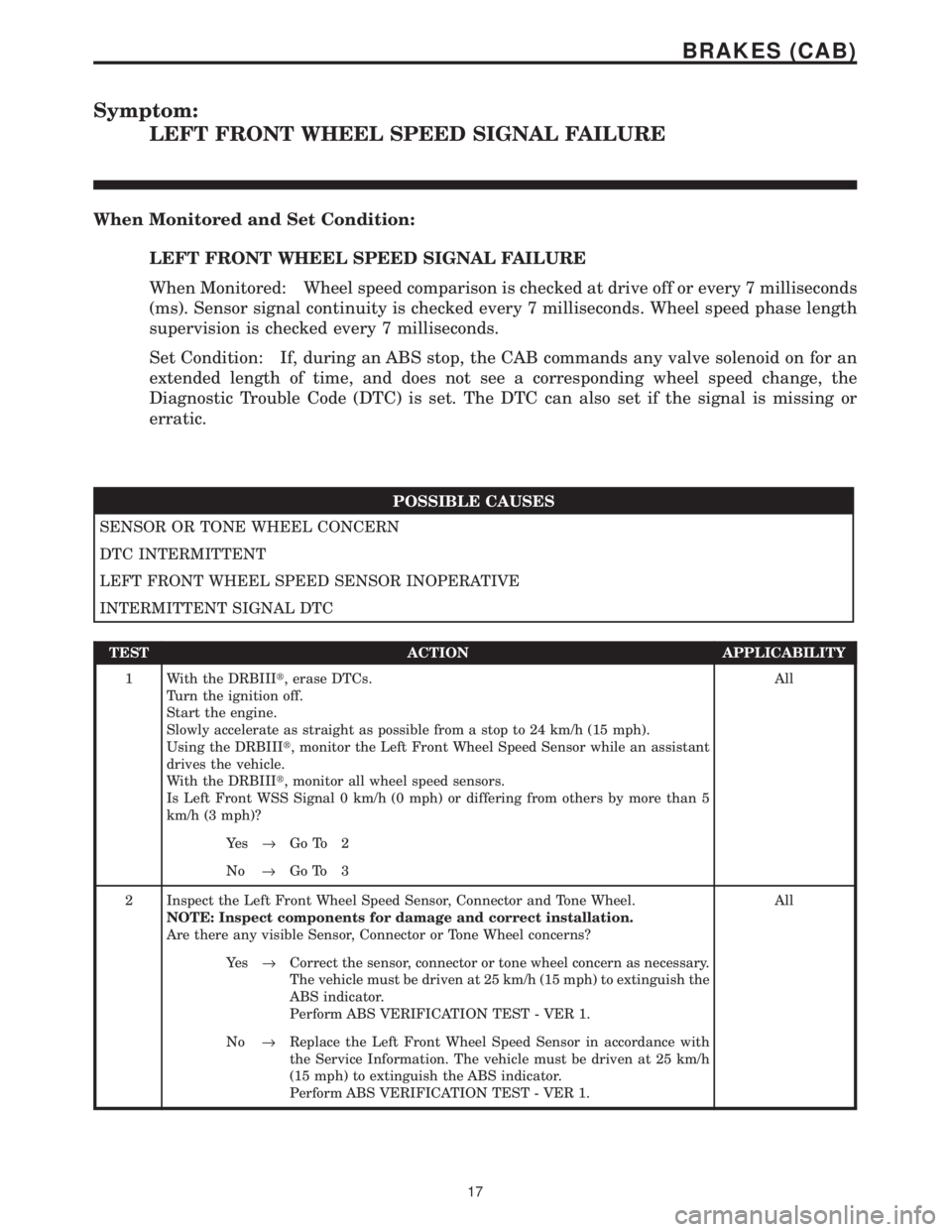
Symptom:
LEFT FRONT WHEEL SPEED SIGNAL FAILURE
When Monitored and Set Condition:
LEFT FRONT WHEEL SPEED SIGNAL FAILURE
When Monitored: Wheel speed comparison is checked at drive off or every 7 milliseconds
(ms). Sensor signal continuity is checked every 7 milliseconds. Wheel speed phase length
supervision is checked every 7 milliseconds.
Set Condition: If, during an ABS stop, the CAB commands any valve solenoid on for an
extended length of time, and does not see a corresponding wheel speed change, the
Diagnostic Trouble Code (DTC) is set. The DTC can also set if the signal is missing or
erratic.
POSSIBLE CAUSES
SENSOR OR TONE WHEEL CONCERN
DTC INTERMITTENT
LEFT FRONT WHEEL SPEED SENSOR INOPERATIVE
INTERMITTENT SIGNAL DTC
TEST ACTION APPLICABILITY
1 With the DRBIIIt, erase DTCs.
Turn the ignition off.
Start the engine.
Slowly accelerate as straight as possible from a stop to 24 km/h (15 mph).
Using the DRBIIIt, monitor the Left Front Wheel Speed Sensor while an assistant
drives the vehicle.
With the DRBIIIt, monitor all wheel speed sensors.
Is Left Front WSS Signal 0 km/h (0 mph) or differing from others by more than 5
km/h (3 mph)?All
Ye s®Go To 2
No®Go To 3
2 Inspect the Left Front Wheel Speed Sensor, Connector and Tone Wheel.
NOTE: Inspect components for damage and correct installation.
Are there any visible Sensor, Connector or Tone Wheel concerns?All
Ye s®Correct the sensor, connector or tone wheel concern as necessary.
The vehicle must be driven at 25 km/h (15 mph) to extinguish the
ABS indicator.
Perform ABS VERIFICATION TEST - VER 1.
No®Replace the Left Front Wheel Speed Sensor in accordance with
the Service Information. The vehicle must be driven at 25 km/h
(15 mph) to extinguish the ABS indicator.
Perform ABS VERIFICATION TEST - VER 1.
17
BRAKES (CAB)
Page 1176 of 4284
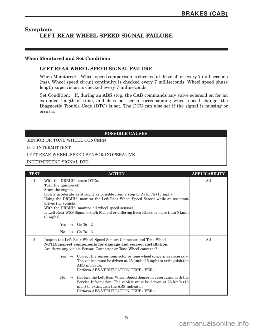
Symptom:
LEFT REAR WHEEL SPEED SIGNAL FAILURE
When Monitored and Set Condition:
LEFT REAR WHEEL SPEED SIGNAL FAILURE
When Monitored: Wheel speed comparison is checked at drive off or every 7 milliseconds
(ms). Wheel speed circuit continuity is checked every 7 milliseconds. Wheel speed phase
length supervision is checked every 7 milliseconds.
Set Condition: If, during an ABS stop, the CAB commands any valve solenoid on for an
extended length of time, and does not see a corresponding wheel speed change, the
Diagnostic Trouble Code (DTC) is set. The DTC can also set if the signal is missing or
erratic.
POSSIBLE CAUSES
SENSOR OR TONE WHEEL CONCERN
DTC INTERMITTENT
LEFT REAR WHEEL SPEED SENSOR INOPERATIVE
INTERMITTENT SIGNAL DTC
TEST ACTION APPLICABILITY
1 With the DRBIIIt, erase DTCs.
Turn the ignition off.
Start the engine.
Slowly accelerate as straight as possible from a stop to 24 km/h (15 mph).
Using the DRBIIIt, monitor the Left Rear Wheel Speed Sensor while an assistant
drives the vehicle.
With the DRBIIIt, monitor all wheel speed sensors.
Is Left Rear WSS Signal 0 km/h (0 mph) or differing from others by more than 5 km/h
(3 mph)?All
Ye s®Go To 2
No®Go To 3
2 Inspect the Left Rear Wheel Speed Sensor, Connector and Tone Wheel.
NOTE: Inspect components for damage and correct installation.
Are there any visible Sensor, Connector or Tone Wheel concerns?All
Ye s®Correct the sensor, connector or tone wheel concern as necessary.
The vehicle must be driven at 25 km/h (15 mph) to extinguish the
ABS indicator.
Perform ABS VERIFICATION TEST - VER 1.
No®Replace the Left Rear Wheel Speed Sensor in accordance with the
Service Information. The vehicle must be driven at 25 km/h (15
mph) to extinguish the ABS indicator.
Perform ABS VERIFICATION TEST - VER 1.
19
BRAKES (CAB)
Page 1181 of 4284
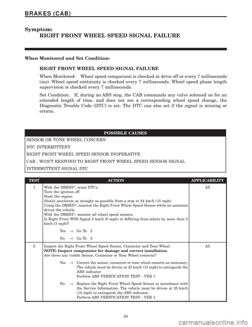
Symptom:
RIGHT FRONT WHEEL SPEED SIGNAL FAILURE
When Monitored and Set Condition:
RIGHT FRONT WHEEL SPEED SIGNAL FAILURE
When Monitored: Wheel speed comparison is checked at drive off or every 7 milliseconds
(ms). Wheel speed continuity is checked every 7 milliseconds. Wheel speed phase length
supervision is checked every 7 milliseconds.
Set Condition: If, during an ABS stop, the CAB commands any valve solenoid on for an
extended length of time, and does not see a corresponding wheel speed change, the
Diagnostic Trouble Code (DTC) is set. The DTC can also set if the signal is missing or
erratic.
POSSIBLE CAUSES
SENSOR OR TONE WHEEL CONCERN
DTC INTERMITTENT
RIGHT FRONT WHEEL SPEED SENSOR INOPERATIVE
CAB - WON'T RESPOND TO RIGHT FRONT WHEEL SPEED SENSOR SIGNAL
INTERMITTENT SIGNAL DTC
TEST ACTION APPLICABILITY
1 With the DRBIIIt, erase DTCs.
Turn the ignition off.
Start the engine.
Slowly accelerate as straight as possible from a stop to 24 km/h (15 mph).
Using the DRBIIIt, monitor the Right Front Wheel Speed Sensor while an assistant
drives the vehicle.
With the DRBIIIt, monitor all wheel speed sensors.
Is Right Front WSS Signal 0 km/h (0 mph) or differing from others by more than 5
km/h (3 mph)?All
Ye s®Go To 2
No®Go To 3
2 Inspect the Right Front Wheel Speed Sensor, Connector and Tone Wheel.
NOTE: Inspect components for damage and correct installation.
Are there any visible Sensor, Connector or Tone Wheel concerns?All
Ye s®Correct the sensor, connector or tone wheel concern as necessary.
The vehicle must be driven at 25 km/h (15 mph) to extinguish the
ABS indicator.
Perform ABS VERIFICATION TEST - VER 1.
No®Replace the Right Front Wheel Speed Sensor in accordance with
the Service Information. The vehicle must be driven at 25 km/h
(15 mph) to extinguish the ABS indicator.
Perform ABS VERIFICATION TEST - VER 1.
24
BRAKES (CAB)
Page 1183 of 4284
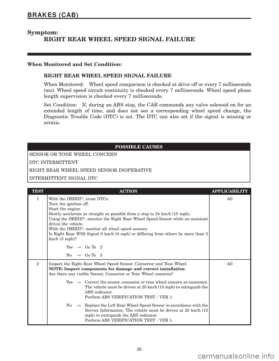
Symptom:
RIGHT REAR WHEEL SPEED SIGNAL FAILURE
When Monitored and Set Condition:
RIGHT REAR WHEEL SPEED SIGNAL FAILURE
When Monitored: Wheel speed comparison is checked at drive off or every 7 milliseconds
(ms). Wheel speed circuit continuity is checked every 7 milliseconds. Wheel speed phase
length supervision is checked every 7 milliseconds.
Set Condition: If, during an ABS stop, the CAB commands any valve solenoid on for an
extended length of time, and does not see a corresponding wheel speed change, the
Diagnostic Trouble Code (DTC) is set. The DTC can also set if the signal is missing or
erratic.
POSSIBLE CAUSES
SENSOR OR TONE WHEEL CONCERN
DTC INTERMITTENT
RIGHT REAR WHEEL SPEED SENSOR INOPERATIVE
INTERMITTENT SIGNAL DTC
TEST ACTION APPLICABILITY
1 With the DRBIIIt, erase DTCs.
Turn the ignition off.
Start the engine.
Slowly accelerate as straight as possible from a stop to 24 km/h (15 mph).
Using the DRBIIIt, monitor the Right Rear Wheel Speed Sensor while an assistant
drives the vehicle.
With the DRBIIIt, monitor all wheel speed sensors.
Is Right Rear WSS Signal 0 km/h (0 mph) or differing from others by more than 5
km/h (3 mph)?All
Ye s®Go To 2
No®Go To 3
2 Inspect the Right Rear Wheel Speed Sensor, Connector and Tone Wheel.
NOTE: Inspect components for damage and correct installation.
Are there any visible Sensor, Connector or Tone Wheel concerns?All
Ye s®Correct the sensor, connector or tone wheel concern as necessary.
The vehicle must be driven at 25 km/h (15 mph) to extinguish the
ABS indicator.
Perform ABS VERIFICATION TEST - VER 1.
No®Replace the Left Rear Wheel Speed Sensor in accordance with the
Service Information. The vehicle must be driven at 25 km/h (15
mph) to extinguish the ABS indicator.
Perform ABS VERIFICATION TEST - VER 1.
26
BRAKES (CAB)
Page 1220 of 4284
1.0 INTRODUCTION
The procedures contained in this manual include
all the specifications, instructions and graphics
needed to diagnose engine control module (ECM)
and sentry key immobilizer system (SKIS) prob-
lems; they are no start, diagnostic trouble code
(DTC), and no trouble code problems for the ECM.
The diagnostics in this manual are based on the
trouble condition or symptom being present at the
time of diagnosis.
When repairs are required, refer to the appropri-
ate service information for the proper removal and
repair procedure.
Diagnostic procedures change every year. New
diagnostic systems may be added; carryover sys-
tems may be enhanced. IT IS RECOMMENDED
THAT YOU REVIEW THE ENTIRE MANUAL TO
BECOME FAMILIAR WITH ALL NEW AND
CHANGED DIAGNOSTIC PROCEDURES.
This manual is designed to begin all diagnosis at
the DTC TEST, which is located at the beginning of
Section 7.0. This will cover all the necessary re-
quirements to begin a logical diagnostic path for
each problem. If there is a diagnostic trouble code
(DTC) detected, it will direct you to the trouble code
test. If there are no DTCs present, it will direct you
by symptom to a no trouble code test.
This book reflects many suggested changes from
readers of past issues. After using this book, if you
have any comments or recommendations, please fill
out the form at the back of the book and mail it back
to us.
1.1 SYSTEM COVERAGE
This diagnostic procedures manual covers all
2001 RG body vehicles equipped with the 2.5L VM
diesel engine.
1.2 SIX-STEP TROUBLESHOOTING
PROCEDURE
Diagnosis of the engine control module (ECM)
and sentry key immobilizer system (SKIS) is done
in six basic steps:
²verification of complaint
²verification of any related symptom
²symptom analysis
²problem isolation
²repair of isolated problem
²verification of proper operation
NOTE: All tests in this manual should be per-
formed with the engine at operating temperature,
unless specified within a particular test.
2.0 IDENTIFICATION OF
SYSTEM
The ECM is located in the left side of the engine
compartment between the left front headlamp and
the intelligent power module. The sentry key immo-
bilizer module (SKIM) is located below the steering
column behind the steering wheel.
3.0 SYSTEM DESCRIPTION AND
FUNCTIONAL OPERATION
3.1 GENERAL DESCRIPTION
The 2.5L VM diesel engine system is equipped
with the latest in technical advances. The on-board
diagnostics incorporated in the engine control mod-
ule and SKIM are intended to assist the field
technician in repairing vehicle problems by the
quickest means.
The engine system incorporates a common rail
fuel delivery design. This design utilizes electroni-
cally controlled solenoid valve type fuel injectors.
Each injector is controlled individually by the ECM.
Injector timing and fuel quantity are controlled by
the ECM based on inputs from the various sensors.
The precision control of the injectors by the ECM
helps to reduce the engine noise, odor and smoke.
3.2 FUNCTIONAL OPERATION
3.2.1 ECM ON-BOARD DIAGNOSTICS
The ECM has been programmed to monitor many
different circuits of the diesel fuel injection system.
This monitoring is called on-board diagnostics.
Certain criteria must be met for a trouble code to
be entered into the ECM memory. The criteria may
be a range of: engine rpm, engine temperature, time
or other input signals to the ECM. If all of the
criteria for monitoring a system or circuit are met,
and a problem is sensed, then a DTC will be stored
in the ECM memory.
It is possible that a DTC for a monitored circuit
may not be entered into the ECM memory, even
though a malfunction has occurred. This may hap-
pen when the monitoring criteria has not been met.
The ECM compares input signal voltages from
each input device with specifications (the estab-
lished high and low limits of the input range) that
are programmed into it for that device. If the input
voltage is not within the specifications and other
trouble code criteria are met, a DTC will be stored
in the ECM memory.
1
GENERAL INFORMATION
Page 1226 of 4284
4.0 DISCLAIMERS, SAFETY,
WARNINGS
4.1 DISCLAIMERS
All information, illustrations, and specifications
contained in this manual are based on the latest
information available at the time of publication.
The right is reserved to make changes at any time
without notice.
4.2 SAFETY
4.2.1 TECHNICIAN SAFETY INFORMATION
WARNING: ENGINES PRODUCE CARBON
MONOXIDE THAT IS ODORLESS, CAUSES
SLOWER REACTION TIME, AND CAN LEAD
TO SERIOUS INJURY. WHEN THE ENGINE IS
OPERATING, KEEP SERVICE AREAS WELL
VENTILATED OR ATTACH THE VEHICLE
EXHAUST SYSTEM TO THE SHOP EXHAUST
REMOVAL SYSTEM.
Set the parking brake and block the wheels before
testing or repairing the vehicle. It is especially
important to block the wheels on front wheel drive
vehicles; the parking brake does not hold the drive
wheels.
When servicing a vehicle, always wear eye pro-
tection, and remove any metal jewelry such as
watchbands or bracelets that might make electrical
contact.
When diagnosing a powertrain system problem,
it is important to follow approved procedures where
applicable. These procedures can be found in the
service manual. Following these procedures is very
important to the safety of individuals performing
diagnostic tests.
4.2.2 VEHICLE PREPARATION FOR
TESTING
Make sure the vehicle being tested has a fully
charged battery. If it does not, false diagnostic codes
or error messages may occur.
4.2.3 SERVICING SUB-ASSEMBLIES
Some components of the powertrain system are
intended to be serviced as an assembly only. At-
tempting to remove or repair certain system sub-
components may result in personal injury and/or
improper system operation. Only those components
with approved repair and installation procedures in
the service manual should be serviced.
4.2.4 DRBIIITSAFETY INFORMATION
WARNING: EXCEEDING THE LIMITS OF THE
DRBIIITMULTIMETER IS DANGEROUS. IT
CAN EXPOSE YOU TO SERIOUS OR
POSSIBLY FATAL INJURY. CAREFULLY
READ AND UNDERSTAND THE CAUTIONS
AND SPECIFICATION LIMITS.
Follow the vehicle manufacturer 's service specifi-
cations at all times.
²Do not use the DRBIIItif it has been damaged.
²Do not use the test leads if the insulation is
damaged or if metal is exposed.
²To avoid electrical shock, do not touch the test
leads, tip or the circuit being tested.
²Choose the proper range and function for the
measurement. Do not try voltage or current mea-
surements that may exceed the rated capacity.
²Do not exceed the limits shown in the table below:
FUNCTION INPUT LIMIT
Volts 0-500 peak volts AC
0-500 volts DC
Ohms (Resistance)* 0-1.12 megohms
Frequency Measure
Frequency Generated0-10 kHz
Temperature -58 - +1100ÉF
-50 - +600ÉC
* Ohms cannot be measured if voltage is present.
Ohms can be measured only in a non-powered
circuit.
²Voltage between any terminal and ground must
not exceed 500v DC or 500v peak AC.
²Use caution when measuring voltage above 25v
DC or 25v AC.
²The circuit being tested must be protected by a 10
amp fuse or circuit breaker.
²Use the low current shunt to measure circuits up
to 10 amps. Use the high current shunt to mea-
sure circuits exceeding 10 amps.
²When testing for the presence of voltage or cur-
rent, make sure the meter is functioning cor-
rectly. Take a reading of a known voltage or
current before accepting a zero reading.
²When measuring current, connect the meter in
series with the load.
²Disconnect the live test lead before disconnecting
the common test lead.
7
GENERAL INFORMATION
Page 1495 of 4284
LUBRICANTS AND GREASES
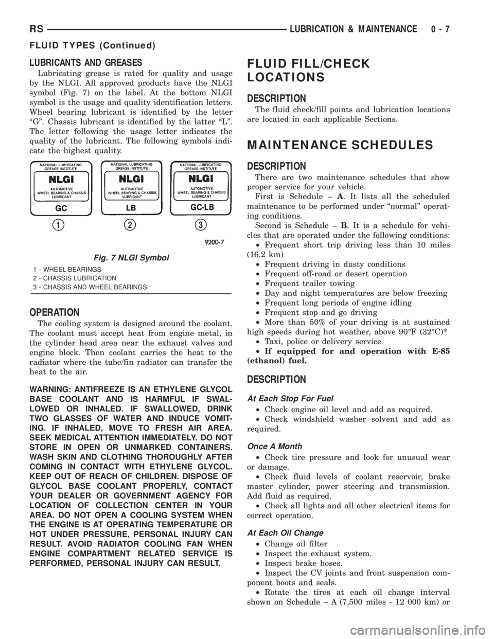
Lubricating grease is rated for quality and usage
by the NLGI. All approved products have the NLGI
symbol (Fig. 7) on the label. At the bottom NLGI
symbol is the usage and quality identification letters.
Wheel bearing lubricant is identified by the letter
ªGº. Chassis lubricant is identified by the latter ªLº.
The letter following the usage letter indicates the
quality of the lubricant. The following symbols indi-
cate the highest quality.
OPERATION
The cooling system is designed around the coolant.
The coolant must accept heat from engine metal, in
the cylinder head area near the exhaust valves and
engine block. Then coolant carries the heat to the
radiator where the tube/fin radiator can transfer the
heat to the air.
WARNING: ANTIFREEZE IS AN ETHYLENE GLYCOL
BASE COOLANT AND IS HARMFUL IF SWAL-
LOWED OR INHALED. IF SWALLOWED, DRINK
TWO GLASSES OF WATER AND INDUCE VOMIT-
ING. IF INHALED, MOVE TO FRESH AIR AREA.
SEEK MEDICAL ATTENTION IMMEDIATELY. DO NOT
STORE IN OPEN OR UNMARKED CONTAINERS.
WASH SKIN AND CLOTHING THOROUGHLY AFTER
COMING IN CONTACT WITH ETHYLENE GLYCOL.
KEEP OUT OF REACH OF CHILDREN. DISPOSE OF
GLYCOL BASE COOLANT PROPERLY, CONTACT
YOUR DEALER OR GOVERNMENT AGENCY FOR
LOCATION OF COLLECTION CENTER IN YOUR
AREA. DO NOT OPEN A COOLING SYSTEM WHEN
THE ENGINE IS AT OPERATING TEMPERATURE OR
HOT UNDER PRESSURE, PERSONAL INJURY CAN
RESULT. AVOID RADIATOR COOLING FAN WHEN
ENGINE COMPARTMENT RELATED SERVICE IS
PERFORMED, PERSONAL INJURY CAN RESULT.
FLUID FILL/CHECK
LOCATIONS
DESCRIPTION
The fluid check/fill points and lubrication locations
are located in each applicable Sections.
MAINTENANCE SCHEDULES
DESCRIPTION
There are two maintenance schedules that show
proper service for your vehicle.
First is Schedule ±A. It lists all the scheduled
maintenance to be performed under ªnormalº operat-
ing conditions.
Second is Schedule ±B. It is a schedule for vehi-
cles that are operated under the following conditions:
²Frequent short trip driving less than 10 miles
(16.2 km)
²Frequent driving in dusty conditions
²Frequent off-road or desert operation
²Frequent trailer towing
²Day and night temperatures are below freezing
²Frequent long periods of engine idling
²Frequent stop and go driving
²More than 50% of your driving is at sustained
high speeds during hot weather, above 90ÉF (32ÉC)*
²Taxi, police or delivery service
²If equipped for and operation with E-85
(ethanol) fuel.
DESCRIPTION
At Each Stop For Fuel
²Check engine oil level and add as required.
²Check windshield washer solvent and add as
required.
Once A Month
²Check tire pressure and look for unusual wear
or damage.
²Check fluid levels of coolant reservoir, brake
master cylinder, power steering and transmission.
Add fluid as required.
²Check all lights and all other electrical items for
correct operation.
At Each Oil Change
²Change oil filter
²Inspect the exhaust system.
²Inspect brake hoses.
²Inspect the CV joints and front suspension com-
ponent boots and seals.
²Rotate the tires at each oil change interval
shown on Schedule ± A (7,500 miles - 12 000 km) or
Fig. 7 NLGI Symbol
1 - WHEEL BEARINGS
2 - CHASSIS LUBRICATION
3 - CHASSIS AND WHEEL BEARINGS
RSLUBRICATION & MAINTENANCE0-7
FLUID TYPES (Continued)
Page 1497 of 4284
112,500 Miles (180 000 km) or at 90 months
²Change the engine oil.
²Replace the engine oil filter.
²Inspect the brake linings.
120,000 Miles (192 000 km) or at 96 months
²Change the engine oil.
²Replace the engine oil filter.
²Replace the engine air cleaner element (fil-
ter).
²Check and replace the PCV valve, if neces-
sary.*
²Inspect the serpentine drive belt. Not required if
replaced at 75,000, 90,000 or 105,000 miles.
²Inspect the tie rod ends and boot seals.
*This maintenance is recommended by Daimler-
Chrysler Corporation to the owner but is not
required to maintain the emissions warranty.
NOTE: Inspection and service should also be per-
formed anytime a malfunction is observed or sus-
pected. Retain all receipts.
SCHEDULE±B±CHRYSLER TOWN AND
COUNTRY VEHICLES
Follow this schedule if the vehicle is usually oper-
ates under one or more of the following conditions.
²Frequent short trip driving less than 5 miles (8
km)
²Frequent driving in dusty conditions
²Frequent trailer towing
²Day and night temperatures are below freezing
²Frequent long periods of engine idling
²Frequent stop and go driving
²More than 50% of your driving is at sustained
high speeds during hot weather, above 90ÉF (32ÉC)*
²Taxi, police or delivery service
²If equipped for and operation with E-85
(ethanol) fuel.
3,000 Miles (5 000 km)
²Change the engine oil.
²Replace the engine oil filter.
6,000 Miles (10 000 km)
²Change the engine oil.
²Replace the engine oil filter.
9,000 Miles (14 000 km)
²Change the engine oil.
²Replace the engine oil filter.
²Inspect the brake linings.
12,000 Miles (19 000 km)
²Change the engine oil.
²Replace the engine oil filter.
15,000 Miles (24 000 km)
²Change the engine oil.
²Replace the engine oil filter.
²Inspect the engine air cleaner element (fil-
ter). Replace as necessary.*
²Change the All Wheel Drive (AWD) power trans-
fer unit fluid. (See the note at the end of Schedule ±
B.)
18,000 Miles (29 000 km)
²Change the engine oil.
²Replace the engine oil filter.
²Inspect the brake linings.
21,000 Miles (34 000 km)
²Change the engine oil.
²Replace the engine oil filter.
²Change the All Wheel Drive (AWD) overrunning
clutch and rear carrier fluid. (See the note at the end
of Schedule ± B.)
24,000 Miles (38 000 km)
²Change the engine oil.
²Replace the engine oil filter.
27,000 Miles (43 000 km)
²Change the engine oil.
²Replace the engine oil filter.
²Inspect the brake linings.
30,000 Miles (48 000 km)
²Change the engine oil.
²Replace the engine oil filter.
²Replace the engine air cleaner element (fil-
ter).
²Inspect the PCV valve, replace as neces-
sary.*
²Change the All Wheel Drive (AWD) power trans-
fer unit fluid. (See the note at the end of Schedule ±
B.)
²Inspect the tie rod ends and boot seals.
33,000 Miles (53 000 km)
²Change the engine oil.
²Replace the engine oil filter.
36,000 Miles (58 000 km)
²Change the engine oil.
²Replace the engine oil filter.
²Inspect the brake linings.
39,000 Miles (62 000 km)
²Change the engine oil.
²Replace the engine oil filter.
RSLUBRICATION & MAINTENANCE0-9
MAINTENANCE SCHEDULES (Continued)