2001 CHRYSLER VOYAGER change wheel
[x] Cancel search: change wheelPage 2700 of 4284
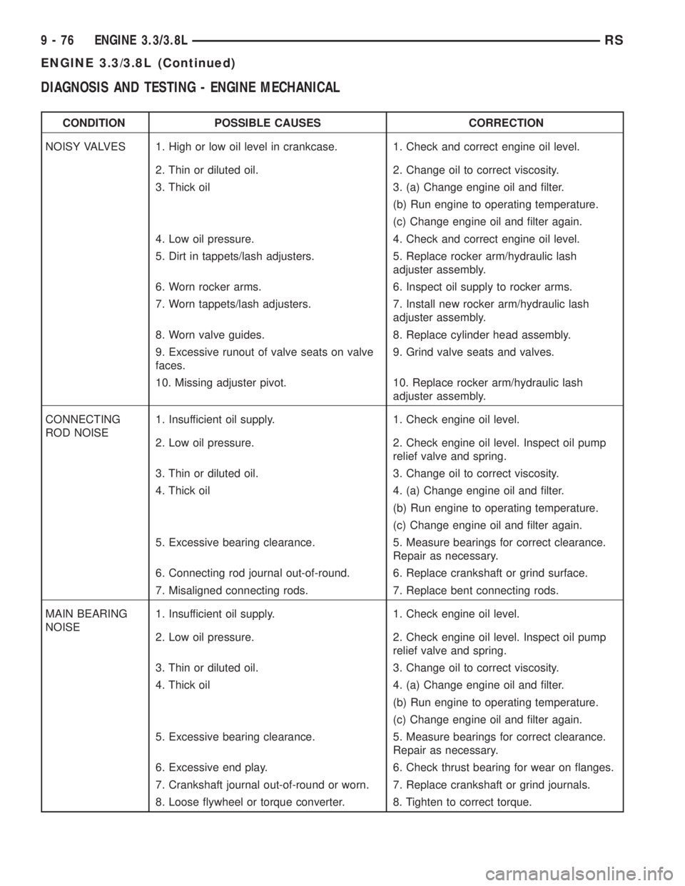
DIAGNOSIS AND TESTING - ENGINE MECHANICAL
CONDITION POSSIBLE CAUSES CORRECTION
NOISY VALVES 1. High or low oil level in crankcase. 1. Check and correct engine oil level.
2. Thin or diluted oil. 2. Change oil to correct viscosity.
3. Thick oil 3. (a) Change engine oil and filter.
(b) Run engine to operating temperature.
(c) Change engine oil and filter again.
4. Low oil pressure. 4. Check and correct engine oil level.
5. Dirt in tappets/lash adjusters. 5. Replace rocker arm/hydraulic lash
adjuster assembly.
6. Worn rocker arms. 6. Inspect oil supply to rocker arms.
7. Worn tappets/lash adjusters. 7. Install new rocker arm/hydraulic lash
adjuster assembly.
8. Worn valve guides. 8. Replace cylinder head assembly.
9. Excessive runout of valve seats on valve
faces.9. Grind valve seats and valves.
10. Missing adjuster pivot. 10. Replace rocker arm/hydraulic lash
adjuster assembly.
CONNECTING
ROD NOISE1. Insufficient oil supply. 1. Check engine oil level.
2. Low oil pressure. 2. Check engine oil level. Inspect oil pump
relief valve and spring.
3. Thin or diluted oil. 3. Change oil to correct viscosity.
4. Thick oil 4. (a) Change engine oil and filter.
(b) Run engine to operating temperature.
(c) Change engine oil and filter again.
5. Excessive bearing clearance. 5. Measure bearings for correct clearance.
Repair as necessary.
6. Connecting rod journal out-of-round. 6. Replace crankshaft or grind surface.
7. Misaligned connecting rods. 7. Replace bent connecting rods.
MAIN BEARING
NOISE1. Insufficient oil supply. 1. Check engine oil level.
2. Low oil pressure. 2. Check engine oil level. Inspect oil pump
relief valve and spring.
3. Thin or diluted oil. 3. Change oil to correct viscosity.
4. Thick oil 4. (a) Change engine oil and filter.
(b) Run engine to operating temperature.
(c) Change engine oil and filter again.
5. Excessive bearing clearance. 5. Measure bearings for correct clearance.
Repair as necessary.
6. Excessive end play. 6. Check thrust bearing for wear on flanges.
7. Crankshaft journal out-of-round or worn. 7. Replace crankshaft or grind journals.
8. Loose flywheel or torque converter. 8. Tighten to correct torque.
9 - 76 ENGINE 3.3/3.8LRS
ENGINE 3.3/3.8L (Continued)
Page 2925 of 4284

STEERING
TABLE OF CONTENTS
page page
STEERING
DESCRIPTION............................1
OPERATION.............................1
DIAGNOSIS AND TESTING..................1
POWER STEERING SYSTEM FLOW AND
PRESSURE TEST........................1STEERING SYSTEM DIAGNOSIS CHARTS....3
SPECIFICATIONS.........................9
SPECIAL TOOLS..........................9
COLUMN...............................10
GEAR.................................17
PUMP.................................24
STEERING
DESCRIPTION - POWER STEERING SYSTEM
This vehicle comes with power steering as stan-
dard equipment and it is the only steering system
available. The power steering system consists of
these major components:
²POWER STEERING PUMP
²POWER STEERING GEAR
²POWER STEERING FLUID RESERVOIR
²POWER STEERING FLUID SUPPLY HOSE
²POWER STEERING FLUID PRESSURE HOSE
²POWER STEERING FLUID RETURN HOSE
²POWER STEERING FLUID COOLER
For information on the first two components, refer
to their respective sections within this service man-
ual group. Information on all other components can
be found in POWER STEERING PUMP.
OPERATION - POWER STEERING SYSTEM
Turning of the steering wheel is converted into linear
(side-to-side) travel through the meshing of the helical
pinion teeth with the rack teeth within the steering
gear. The lateral travel pushes and pulls the tie rods to
change the direction of the vehicle's front wheels.
Power assist steering is provided by a belt driven
rotary type pump. It directs fluid through power
steering fluid hoses to the power steering gear where
it is used to assist the driver's turning effort.
Manual steering control of the vehicle can be main-
tained if power steering assist is lost. However, under
this condition, steering effort is significantly increased.
DIAGNOSIS AND TESTING - POWER STEERING
SYSTEM FLOW AND PRESSURE TEST
ALL ENGINES
The following procedure is to be used to test the
operation of the power steering system on this vehi-
cle. This test will provide the flow rate of the power
steering pump along with the maximum relief pres-sure. This test is to be performed any time a power
steering system problem is present to determine if
the power steering pump or power steering gear is
not functioning properly. The following flow and pres-
sure test is performed using the Power Steering Ana-
lyzer Kit, Special Tool 6815 (Fig. 1), hoses, Special
Tools 6905 and 6959, and fittings from adapter kit,
Special Tool 6893.
Assemble hoses on Power Steering Analyzer, Spe-
cial Tool 6815, as shown. Install Pressure Hose, Spe-
cial Tool 6905 (in 6893 kit), in the inlet fitting on
Power Steering Analyzer. Install Pressure Hose, Spe-
cial Tool 6713 (in 6815 kit) on Pressure Hose, Special
Tool 6905. Install Pressure Hose, Special Tool 6959,
in the outlet fitting on Power Steering Analyzer.
Install the following adapters from Adapter Set,
Special Tool 6893 (Fig. 2), on the analyzer hose ends:
Install Adapter Fitting, Special Tool 6844, on Pres-
sure Hose, Special Tool 6713. Install Adapter Fitting,
Special Tool 6826, on Pressure Hose, Special Tool
6959.
Fig. 1 Power Steering Analyzer With Hoses Installed
1 - OUTLET
2 - SPECIAL TOOL 6815
3 - INLET
RSSTEERING19-1
Page 2942 of 4284
ing gear. This travel pushes and pulls the tie rods to
change the direction of the vehicle's front wheels.
Power assist steering provided by the power steer-
ing pump is controlled by an open center, rotary type
control valve which directs oil from the pump to
either side of the integral rack piston upon demand.
Road feel is controlled by the diameter of a torsion
bar which initially steers the vehicle. As required
steering effort increases, as in a turn, the torsion bar
twists, causing relative rotary motion between the
rotary valve body and the valve spool. This move-
ment directs oil behind the integral rack piston
which, in turn, builds up hydraulic pressure and
assists in the turning effort.
Manual steering control of the vehicle can be main-
tained if power steering assist is lost. However,
under this condition, steering effort is significantly
increased.
SERVICE WARNINGS AND CAUTIONS
WARNING: POWER STEERING FLUID, ENGINE
PARTS AND EXHAUST SYSTEM MAY BE
EXTREMELY HOT IF ENGINE HAS BEEN RUNNING.
DO NOT START ENGINE WITH ANY LOOSE OR DIS-
CONNECTED HOSES. DO NOT ALLOW HOSES TO
TOUCH HOT EXHAUST MANIFOLD OR CATALYST.
WARNING: FLUID LEVEL SHOULD BE CHECKED
WITH THE ENGINE OFF TO PREVENT PERSONAL
INJURY FROM MOVING PARTS.
CAUTION: When the system is open, cap all open
ends of the hoses, power steering pump fittings or
power steering gear ports to prevent entry of for-
eign material into the components.
REMOVAL - GEAR
CAUTION: Positioning the steering column in the
locked position will prevent the clockspring from
being accidentally over-extended when the steering
column is disconnected from the intermediate
steering coupler.
(1) Remove cap from power steering fluid reser-
voir.
(2) Using a siphon pump, remove as much fluid as
possible from the power steering fluid reservoir.
(3) With the ignition key in the locked position
turn the steering wheel to the left until the steering
wheel is in the locked position.
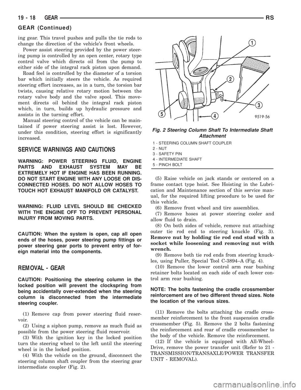
(4) With the vehicle on the ground, disconnect the
steering column shaft coupler from the steering gear
intermediate coupler (Fig. 2).(5) Raise vehicle on jack stands or centered on a
frame contact type hoist. See Hoisting in the Lubri-
cation and Maintenance section of this service man-
ual, for the required lifting procedure to be used for
this vehicle.
(6) Remove front wheel and tire assemblies.
(7) Remove hoses at power steering cooler and
allow fluid to drain.
(8) On both sides of vehicle, remove nut attaching
outer tie rod end to steering knuckle (Fig. 3).
Remove nut by holding tie rod end stud with a
socket while loosening and removing nut with
wrench.
(9) Remove both tie rod ends from steering knuck-
les, using Puller, Special Tool C-3894±A (Fig. 4).
(10) Remove the lower control arm rear bushing
retainer bolts located on each side of each lower con-
trol arm rear bushing.
NOTE: The bolts fastening the cradle crossmember
reinforcement are of two different thread sizes. Note
the location of the various sizes.
(11) Remove the bolts attaching the cradle cross-
member reinforcement to the front suspension cradle
crossmember (Fig. 5). Remove the 2 bolts fastening
the reinforcement and rear of cradle crossmember to
the body of the vehicle. Remove the reinforcement.
(12) If the vehicle is equipped with All-Wheel-
Drive, remove the power transfer unit (Refer to 21 -
TRANSMISSION/TRANSAXLE/POWER TRANSFER
UNIT - REMOVAL).
Fig. 2 Steering Column Shaft To Intermediate Shaft
Attachment
1 - STEERING COLUMN SHAFT COUPLER
2 - NUT
3 - SAFETY PIN
4 - INTERMEDIATE SHAFT
5 - PINCH BOLT
19 - 18 GEARRS
GEAR (Continued)
Page 2986 of 4284
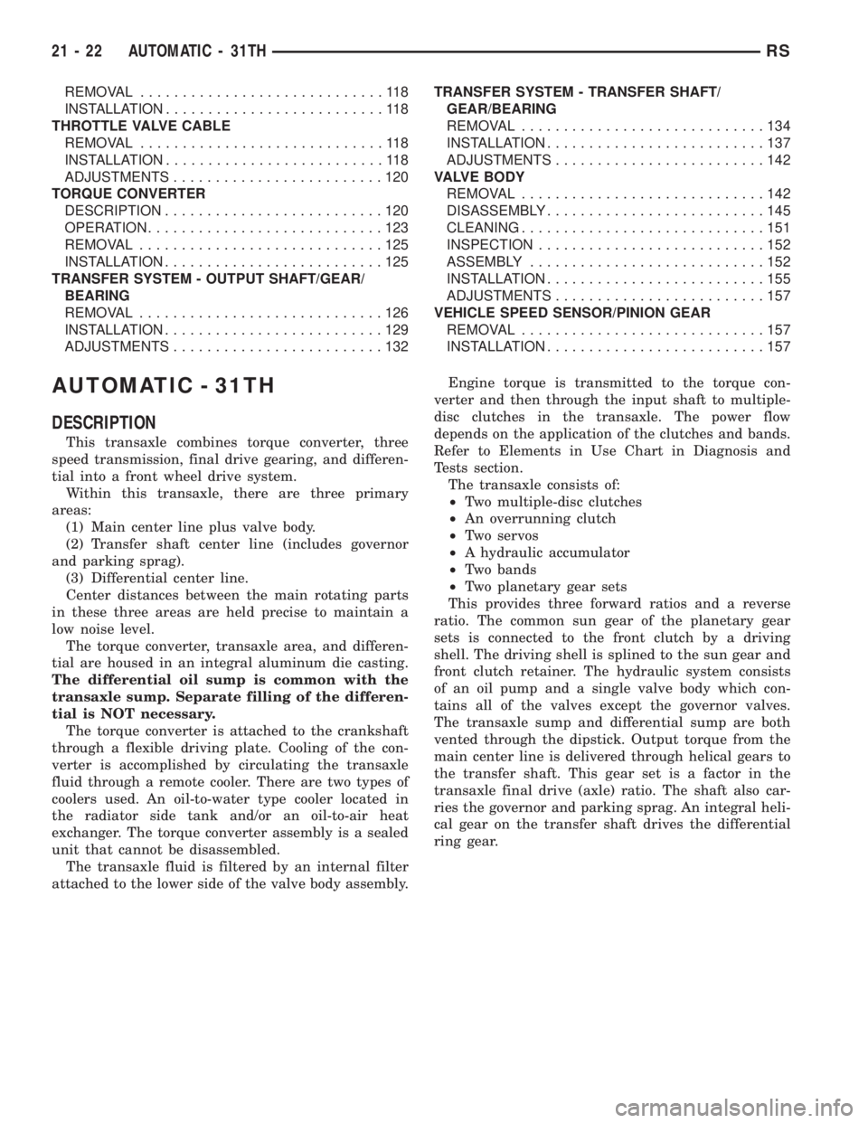
REMOVAL.............................118
INSTALLATION..........................118
THROTTLE VALVE CABLE
REMOVAL.............................118
INSTALLATION..........................118
ADJUSTMENTS.........................120
TORQUE CONVERTER
DESCRIPTION..........................120
OPERATION............................123
REMOVAL.............................125
INSTALLATION..........................125
TRANSFER SYSTEM - OUTPUT SHAFT/GEAR/
BEARING
REMOVAL.............................126
INSTALLATION..........................129
ADJUSTMENTS.........................132TRANSFER SYSTEM - TRANSFER SHAFT/
GEAR/BEARING
REMOVAL.............................134
INSTALLATION..........................137
ADJUSTMENTS.........................142
VALVE BODY
REMOVAL.............................142
DISASSEMBLY..........................145
CLEANING.............................151
INSPECTION...........................152
ASSEMBLY............................152
INSTALLATION..........................155
ADJUSTMENTS.........................157
VEHICLE SPEED SENSOR/PINION GEAR
REMOVAL.............................157
INSTALLATION..........................157
AUTOMATIC - 31TH
DESCRIPTION
This transaxle combines torque converter, three
speed transmission, final drive gearing, and differen-
tial into a front wheel drive system.
Within this transaxle, there are three primary
areas:
(1) Main center line plus valve body.
(2) Transfer shaft center line (includes governor
and parking sprag).
(3) Differential center line.
Center distances between the main rotating parts
in these three areas are held precise to maintain a
low noise level.
The torque converter, transaxle area, and differen-
tial are housed in an integral aluminum die casting.
The differential oil sump is common with the
transaxle sump. Separate filling of the differen-
tial is NOT necessary.
The torque converter is attached to the crankshaft
through a flexible driving plate. Cooling of the con-
verter is accomplished by circulating the transaxle
fluid through a remote cooler. There are two types of
coolers used. An oil-to-water type cooler located in
the radiator side tank and/or an oil-to-air heat
exchanger. The torque converter assembly is a sealed
unit that cannot be disassembled.
The transaxle fluid is filtered by an internal filter
attached to the lower side of the valve body assembly.Engine torque is transmitted to the torque con-
verter and then through the input shaft to multiple-
disc clutches in the transaxle. The power flow
depends on the application of the clutches and bands.
Refer to Elements in Use Chart in Diagnosis and
Tests section.
The transaxle consists of:
²Two multiple-disc clutches
²An overrunning clutch
²Two servos
²A hydraulic accumulator
²Two bands
²Two planetary gear sets
This provides three forward ratios and a reverse
ratio. The common sun gear of the planetary gear
sets is connected to the front clutch by a driving
shell. The driving shell is splined to the sun gear and
front clutch retainer. The hydraulic system consists
of an oil pump and a single valve body which con-
tains all of the valves except the governor valves.
The transaxle sump and differential sump are both
vented through the dipstick. Output torque from the
main center line is delivered through helical gears to
the transfer shaft. This gear set is a factor in the
transaxle final drive (axle) ratio. The shaft also car-
ries the governor and parking sprag. An integral heli-
cal gear on the transfer shaft drives the differential
ring gear.
21 - 22 AUTOMATIC - 31THRS
Page 3657 of 4284
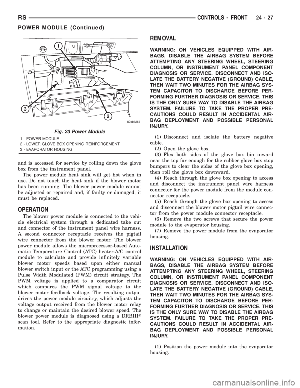
and is accessed for service by rolling down the glove
box from the instrument panel.
The power module heat sink will get hot when in
use. Do not touch the heat sink if the blower motor
has been running. The blower power module cannot
be adjusted or repaired and, if faulty or damaged, it
must be replaced.
OPERATION
The blower power module is connected to the vehi-
cle electrical system through a dedicated take out
and connector of the instrument panel wire harness.
A second connector receptacle receives the pigtail
wire connector from the blower motor. The blower
power module allows the microprocessor-based Auto-
matic Temperature Control (ATC) heater-A/C control
module to calculate and provide infinitely variable
blower motor speeds based upon either manual
blower switch input or the ATC programming using a
Pulse Width Modulated (PWM) circuit strategy. The
PWM voltage is applied to a comparator circuit
which compares the PWM signal voltage to the
blower motor feedback voltage. The resulting output
drives the power module circuitry, which adjusts the
voltage output received from the blower motor relay
to change or maintain the desired blower speed. The
blower power module is diagnosed using a DRBIIIt
scan tool. Refer to the appropriate diagnostic infor-
mation.
REMOVAL
WARNING: ON VEHICLES EQUIPPED WITH AIR-
BAGS, DISABLE THE AIRBAG SYSTEM BEFORE
ATTEMPTING ANY STEERING WHEEL, STEERING
COLUMN, OR INSTRUMENT PANEL COMPONENT
DIAGNOSIS OR SERVICE. DISCONNECT AND ISO-
LATE THE BATTERY NEGATIVE (GROUND) CABLE,
THEN WAIT TWO MINUTES FOR THE AIRBAG SYS-
TEM CAPACITOR TO DISCHARGE BEFORE PER-
FORMING FURTHER DIAGNOSIS OR SERVICE. THIS
IS THE ONLY SURE WAY TO DISABLE THE AIRBAG
SYSTEM. FAILURE TO TAKE THE PROPER PRE-
CAUTIONS COULD RESULT IN ACCIDENTAL AIR-
BAG DEPLOYMENT AND POSSIBLE PERSONAL
INJURY.
(1) Disconnect and isolate the battery negative
cable.
(2) Open the glove box.
(3) Flex both sides of the glove box bin inward
near the top far enough for the rubber glove box stop
bumpers to clear the sides of the glove box opening,
then roll the glove box downward.
(4) Reach through the glove box opening to access
and disconnect the instrument panel wire harness
connector for the power module from the module con-
nector receptacle.
(5) Reach through the glove box opening to access
and disconnect the blower motor pigtail wire connec-
tor from the power module connector receptacle.
(6) Remove the two screws that secure the power
module to the evaporator housing.
(7) Remove the power module from the evaporator
housing.
INSTALLATION
WARNING: ON VEHICLES EQUIPPED WITH AIR-
BAGS, DISABLE THE AIRBAG SYSTEM BEFORE
ATTEMPTING ANY STEERING WHEEL, STEERING
COLUMN, OR INSTRUMENT PANEL COMPONENT
DIAGNOSIS OR SERVICE. DISCONNECT AND ISO-
LATE THE BATTERY NEGATIVE (GROUND) CABLE,
THEN WAIT TWO MINUTES FOR THE AIRBAG SYS-
TEM CAPACITOR TO DISCHARGE BEFORE PER-
FORMING FURTHER DIAGNOSIS OR SERVICE. THIS
IS THE ONLY SURE WAY TO DISABLE THE AIRBAG
SYSTEM. FAILURE TO TAKE THE PROPER PRE-
CAUTIONS COULD RESULT IN ACCIDENTAL AIR-
BAG DEPLOYMENT AND POSSIBLE PERSONAL
INJURY.
(1) Position the power module into the evaporator
housing.
Fig. 23 Power Module
1 - POWER MODULE
2 - LOWER GLOVE BOX OPENING REINFORCEMENT
3 - EVAPORATOR HOUSING
RSCONTROLS - FRONT24-27
POWER MODULE (Continued)
Page 3706 of 4284

connector receptacle on the top of the expansion
valve.
(7) Remove the tape or plugs from the front liquid
line rear section and suction line fittings for the
expansion valve and both ports on the front of the
expansion valve.
(8) Lubricate new rubber O-ring seals with clean
refrigerant oil and install them on the front liquid
line rear section and suction line fittings for the
expansion valve.
(9) Reconnect the liquid line and suction line fit-
tings to the expansion valve.
(10) Install and tighten the nut that secures the
suction line and liquid line fittings to the stud on the
expansion valve. Tighten the nut to 23 N´m (17 ft.
lbs.).
(11) Remove the tape or plugs from the liquid line
rear section fitting for the filter-drier and the filter-
drier outlet port.
(12) Lubricate a new rubber O-ring seal with clean
refrigerant oil and install it on the liquid line fitting.
(13) Reconnect the liquid line fitting to the filter-
drier outlet port on the top of the filter-drier.
(14) Install and tighten the screw that secures the
liquid line fitting to the filter-drier. Tighten the screw
to 2 N´m (18 in. lbs.).
(15) Reconnect the headlamp and dash wire har-
ness connector for the A/C pressure transducer to the
transducer on the front liquid line rear section.
(16) Reconnect the drain tube to the wiper module
drain on the right side of the engine compartment.
(17) Reinstall the air cleaner housing into the
right side of the engine compartment.
(18) Reconnect the battery negative cable.
(19) Evacuate the refrigerant system. (Refer to 24
- HEATING & AIR CONDITIONING/PLUMBING -
FRONT/REFRIGERANT - STANDARD PROCE-
DURE - REFRIGERANT SYSTEM EVACUATE).
(20) Charge the refrigerant system. (Refer to 24 -
HEATING & AIR CONDITIONING/PLUMBING -
FRONT/REFRIGERANT - STANDARD PROCE-
DURE - REFRIGERANT SYSTEM CHARGE).
HEATER CORE
DESCRIPTION
The heater core is located in the distribution hous-
ing of the heater-A/C unit, under the instrument
panel. It is a heat exchanger made of rows of tubes
and fins. One end of the core is fitted with a molded
plastic tank that includes integral heater core inlet
and outlet ports. The removable heater core tubes
are held in place these ports by a sealing plate
secured with a screw to the heater core tank. This
removable heater core tube arrangement allows theheater core to be serviced without removing the heat-
er-A/C unit housing from the vehicle. The heater core
cannot be repaired and, if faulty or damaged, it must
be replaced.
OPERATION
Engine coolant is circulated through heater hoses
to the heater core at all times. As the coolant flows
through the heater core, heat removed from the
engine is transferred to the heater core fins and
tubes. Air directed through the heater core picks up
the heat from the heater core fins. The blend air door
allows control of the heater output air temperature
by controlling how much of the air flowing through
the heater-A/C unit housing is directed through the
heater core.
REMOVAL- HEATER CORE EXTENSION TUBES
WARNING: REFER TO THE APPLICABLE WARN-
INGS AND CAUTIONS FOR THIS SYSTEM BEFORE
PERFORMING THE FOLLOWING OPERATION.
(Refer to 24 - HEATING & AIR CONDITIONING/
PLUMBING FRONT - WARNING - HEATER PLUMB-
ING).
WARNING: ON VEHICLES EQUIPPED WITH AIR-
BAGS, DISABLE THE AIRBAG SYSTEM BEFORE
ATTEMPTING ANY STEERING WHEEL, STEERING
COLUMN, OR INSTRUMENT PANEL COMPONENT
DIAGNOSIS OR SERVICE. DISCONNECT AND ISO-
LATE THE BATTERY NEGATIVE (GROUND) CABLE,
THEN WAIT TWO MINUTES FOR THE AIRBAG SYS-
TEM CAPACITOR TO DISCHARGE BEFORE PER-
FORMING FURTHER DIAGNOSIS OR SERVICE. THIS
IS THE ONLY SURE WAY TO DISABLE THE AIRBAG
SYSTEM. FAILURE TO TAKE THE PROPER PRE-
CAUTIONS COULD RESULT IN ACCIDENTAL AIR-
BAG DEPLOYMENT AND POSSIBLE PERSONAL
INJURY.
(1) Drain the engine cooling system. (Refer to 7 -
COOLING - STANDARD PROCEDURE - COOLING
SYSTEM DRAIN).
(2) Disconnect and isolate the battery negative
cable.
(3) Disconnect the heater hoses from the heater
hose tubes. (Refer to 24 - HEATING & AIR CONDI-
TIONING/PLUMBING - FRONT/HEATER HOSE -
REMOVAL).
(4) Remove the silencer from beneath the driver
side end of the instrument panel. (Refer to 23 -
BODY/INSTRUMENT PANEL/INSTRUMENT
PANEL SILENCER - REMOVAL).
24 - 76 PLUMBING - FRONTRS
EXPANSION VALVE (Continued)
Page 3730 of 4284
(2) Lubricate new rubber O-ring seals with clean
refrigerant oil and install them on the evaporator
tube fittings.
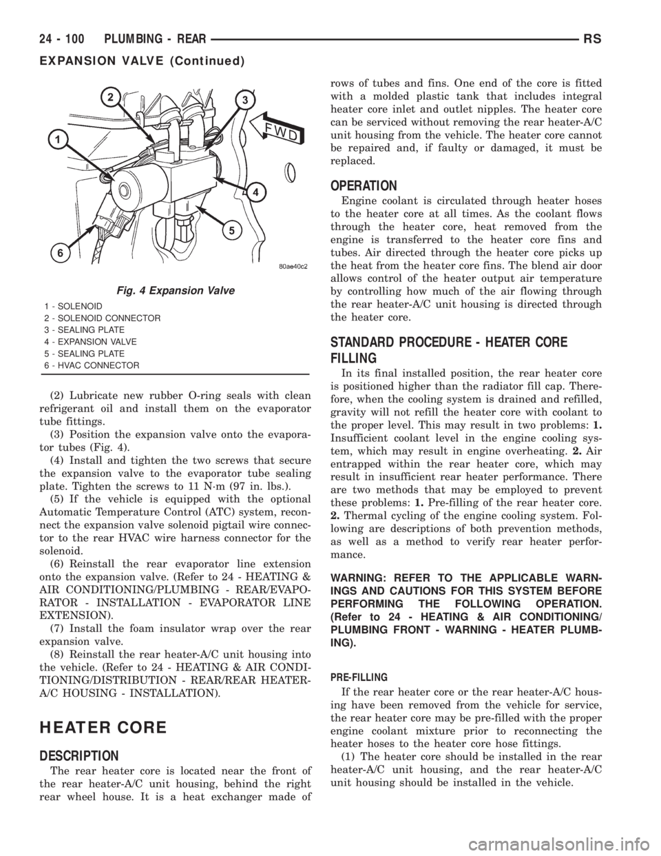
(3) Position the expansion valve onto the evapora-
tor tubes (Fig. 4).
(4) Install and tighten the two screws that secure
the expansion valve to the evaporator tube sealing
plate. Tighten the screws to 11 N´m (97 in. lbs.).
(5) If the vehicle is equipped with the optional
Automatic Temperature Control (ATC) system, recon-
nect the expansion valve solenoid pigtail wire connec-
tor to the rear HVAC wire harness connector for the
solenoid.
(6) Reinstall the rear evaporator line extension
onto the expansion valve. (Refer to 24 - HEATING &
AIR CONDITIONING/PLUMBING - REAR/EVAPO-
RATOR - INSTALLATION - EVAPORATOR LINE
EXTENSION).
(7) Install the foam insulator wrap over the rear
expansion valve.
(8) Reinstall the rear heater-A/C unit housing into
the vehicle. (Refer to 24 - HEATING & AIR CONDI-
TIONING/DISTRIBUTION - REAR/REAR HEATER-
A/C HOUSING - INSTALLATION).
HEATER CORE
DESCRIPTION
The rear heater core is located near the front of
the rear heater-A/C unit housing, behind the right
rear wheel house. It is a heat exchanger made ofrows of tubes and fins. One end of the core is fitted
with a molded plastic tank that includes integral
heater core inlet and outlet nipples. The heater core
can be serviced without removing the rear heater-A/C
unit housing from the vehicle. The heater core cannot
be repaired and, if faulty or damaged, it must be
replaced.
OPERATION
Engine coolant is circulated through heater hoses
to the heater core at all times. As the coolant flows
through the heater core, heat removed from the
engine is transferred to the heater core fins and
tubes. Air directed through the heater core picks up
the heat from the heater core fins. The blend air door
allows control of the heater output air temperature
by controlling how much of the air flowing through
the rear heater-A/C unit housing is directed through
the heater core.
STANDARD PROCEDURE - HEATER CORE
FILLING
In its final installed position, the rear heater core
is positioned higher than the radiator fill cap. There-
fore, when the cooling system is drained and refilled,
gravity will not refill the heater core with coolant to
the proper level. This may result in two problems:1.
Insufficient coolant level in the engine cooling sys-
tem, which may result in engine overheating.2.Air
entrapped within the rear heater core, which may
result in insufficient rear heater performance. There
are two methods that may be employed to prevent
these problems:1.Pre-filling of the rear heater core.
2.Thermal cycling of the engine cooling system. Fol-
lowing are descriptions of both prevention methods,
as well as a method to verify rear heater perfor-
mance.
WARNING: REFER TO THE APPLICABLE WARN-
INGS AND CAUTIONS FOR THIS SYSTEM BEFORE
PERFORMING THE FOLLOWING OPERATION.
(Refer to 24 - HEATING & AIR CONDITIONING/
PLUMBING FRONT - WARNING - HEATER PLUMB-
ING).
PRE-FILLING
If the rear heater core or the rear heater-A/C hous-
ing have been removed from the vehicle for service,
the rear heater core may be pre-filled with the proper
engine coolant mixture prior to reconnecting the
heater hoses to the heater core hose fittings.
(1) The heater core should be installed in the rear
heater-A/C unit housing, and the rear heater-A/C
unit housing should be installed in the vehicle.
Fig. 4 Expansion Valve
1 - SOLENOID
2 - SOLENOID CONNECTOR
3 - SEALING PLATE
4 - EXPANSION VALVE
5 - SEALING PLATE
6 - HVAC CONNECTOR
24 - 100 PLUMBING - REARRS
EXPANSION VALVE (Continued)
Page 3804 of 4284
SYMPTOM DIAGNOSTIC TEST
POOR FUEL ECONOMY CHECKING PCM POWER AND GND CKT
CHECKING THE FUEL PRESSURE
CHECKING ECT SENSOR
CHECKING THROTTLE POSITION SENSOR
CHECKING MAP SENSOR
CHECKING IDLE AIR CONTROL MOTOR OPERATION
CHECKING IAT SENSOR
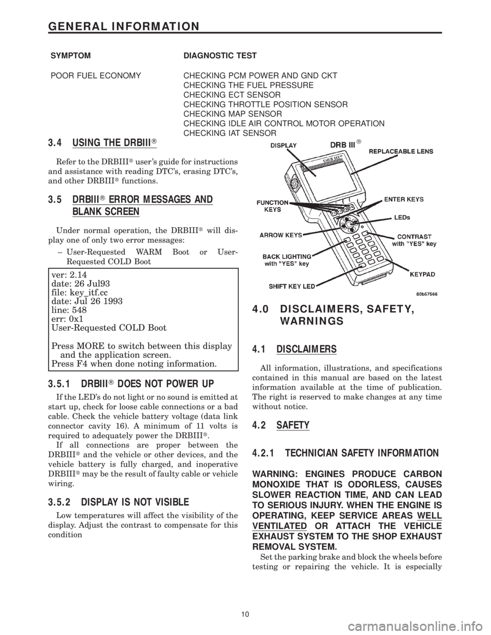
3.4 USING THE DRBIIIT
Refer to the DRBIIItuser 's guide for instructions
and assistance with reading DTC's, erasing DTC's,
and other DRBIIItfunctions.
3.5 DRBIIITERROR MESSAGES AND
BLANK SCREEN
Under normal operation, the DRBIIItwill dis-
play one of only two error messages:
± User-Requested WARM Boot or User-
Requested COLD Boot
ver: 2.14
date: 26 Jul93
file: key_itf.cc
date: Jul 26 1993
line: 548
err: 0x1
User-Requested COLD Boot
Press MORE to switch between this display
and the application screen.
Press F4 when done noting information.
3.5.1 DRBIIITDOES NOT POWER UP
If the LED's do not light or no sound is emitted at
start up, check for loose cable connections or a bad
cable. Check the vehicle battery voltage (data link
connector cavity 16). A minimum of 11 volts is
required to adequately power the DRBIIIt.
If all connections are proper between the
DRBIIItand the vehicle or other devices, and the
vehicle battery is fully charged, and inoperative
DRBIIItmay be the result of faulty cable or vehicle
wiring.
3.5.2 DISPLAY IS NOT VISIBLE
Low temperatures will affect the visibility of the
display. Adjust the contrast to compensate for this
condition
4.0 DISCLAIMERS, SAFETY,
WARNINGS
4.1 DISCLAIMERS
All information, illustrations, and specifications
contained in this manual are based on the latest
information available at the time of publication.
The right is reserved to make changes at any time
without notice.
4.2 SAFETY
4.2.1 TECHNICIAN SAFETY INFORMATION
WARNING: ENGINES PRODUCE CARBON
MONOXIDE THAT IS ODORLESS, CAUSES
SLOWER REACTION TIME, AND CAN LEAD
TO SERIOUS INJURY. WHEN THE ENGINE IS
OPERATING, KEEP SERVICE AREAS WELL
VENTILATED OR ATTACH THE VEHICLE
EXHAUST SYSTEM TO THE SHOP EXHAUST
REMOVAL SYSTEM.
Set the parking brake and block the wheels before
testing or repairing the vehicle. It is especially
10
GENERAL INFORMATION