2001 CHRYSLER VOYAGER fuel cap
[x] Cancel search: fuel capPage 48 of 4284
3.9.2.11 HVAC DIAGNOSTICS
The A/C ± Heater Control Module is fully addres-
sable with the DRBIIIt. Two of the Control Mod-
ule's diagnostic capabilities that the DRBIIItwill
actuate include the A/C Cooldown Test to test A/C
system performance and the HVAC Door Recalibra-
tion Test to determine actuator travel span. After
performing either test, the Control Module will
display one or more messages on the DRBIIIt
screen. The message will indicate either that the
HVAC system passed the test or that there is a fault
currently active in the HVAC system. The DRBIIIt
can also extract active and stored Diagnostic Trou-
ble Codes (DTCs) from the control module. Active
DTCs are faults that currently exit in the HVAC
system. Active DTCs cannot be erased until the
condition causing the code is repaired. Stored DTCs
are faults that occurred in the HVAC system since
the control module received the last ªclear diagnos-
tic infoº message.
3.10 CABIN HEATER
NOTE: The Cabin Heater, also known as the
Diesel Cabin Heater Assist (DCHA), will be
referred to as the DCHA throughout most of
the General Information and the Diagnostic
Procedures in this manual.
3.10.1 GENERAL SAFETY INFORMATION
WARNING: DO NOT OPERATE THE DCHA IN
AN ENCLOSED AREA SUCH AS A GARAGE
THAT DOES NOT HAVE EXHAUST
VENTILATION FACILITIES. ALWAYS VENT
THE DCHA's EXHAUST WHEN OPERATING
THE DCHA. FAILURE TO FOLLOW THESE
INSTRUCTIONS MAY RESULT IN PERSONAL
INJURY OR DEATH.
WARNING: ALLOW THE DCHA ASSEMBLY
TO COOL BEFORE PERFORMING A COM-
PONENT INSPECTION/REPAIR/REPLACE-
MENT. FAILURE TO FOLLOW THESE
INSTRUCTIONS MAY RESULT IN PERSONAL
INJURY.
WARNING: ALWAYS DISCONNECT THE
VEHICLE'S BATTERY PRIOR TO PER-
FORMING ANY TYPE OF WORK ON THE
DCHA. FAILURE TO FOLLOW THESE
INSTRUCTIONS MAY RESULT IN PERSONAL
INJURY OR DEATH.WARNING: NEVER ATTEMPT TO REPAIR THE
DCHA HEATER MODULE OR ANY OF ITS
INTERNAL COMPONENTS. ALWAYS PER-
FORM DCHA COMPONENT REPLACEMENT
IN ACCORDANCE WITH THE SERVICE
INFORMATION. FAILURE TO FOLLOW
THESE INSTRUCTIONS MAY RESULT IN
PERSONAL INJURY OR DEATH.
CAUTION: Do not actuate the DCHA Field
Mode Test with the engine off. Failure to
follow these instructions may result in
internal damage to the DCHA Heater Module.
CAUTION: Always Perform The Cabin Heater
Pre-Test Prior To Performing Any Other Cabin
Heater Test For The Test Result To Be Valid.
NOTE: Do not disconnect the vehicle's
battery or the DCHA's main power-supply
while the DCHA is in operation or in
run-down mode. Failure to follow these
instructions may result in excess emissions
from the DCHA Heater Module.
NOTE: Failure to prime the Dosing Pump
after draining the DCHA fuel line will prevent
DCHA heater activation during the first
attempt to start the heater. This will also set a
Diagnostic Trouble Code (DTC) in the DCHA
Control's memory. Do not perform the Dosing
Pump Priming Procedure if an attempt was
made to start the DCHA without priming the
Dosing Pump first. This will put excess fuel
in the DCHA Heater Module and cause smoke
to emit from the DCHA exhaust pipe when
heater activation occurs.
NOTE: Waxed fuel can obstruct the fuel line
and reduce flow. Check for the appropriate
winter grade fuel and replace as necessary.
3.10.2 COMPONENT DESCRIPTION AND
OPERATION
3.10.2.1 DCHA ASSEMBLY
The DCHA is a supplemental heater designed to
pre-heat the engine's coolant in order to supply the
vehicle's occupants with heat prior to the engine
reaching operating temperature. The DCHA assem-
bly mounts underneath the vehicle on the left side
floor pan near the front door opening. The DCHA
assembly connects to the vehicle's heater hoses and
has a fuel supply line that connects to the vehicle's
fuel tank.
19
GENERAL INFORMATION
Page 49 of 4284

The DCHA assembly consists of a:
²combustion air fan assembly
²burner housing
²burner insert
²control unit/heat exchanger
²combustion chamber
²dosing pump
3.10.2.2 COMBUSTION AIR FAN
The combustion air fan assembly includes the:
²combustion air fan
²combustion air fan inlet
²fuel supply inlet
The combustion air fan delivers the air required
for combustion from the combustion air inlet to the
burner insert.
3.10.2.3 BURNER HOUSING
The burner housing includes the:
²coolant inlet
²coolant outlet
²exhaust outlet
The burner housing accommodates the burner
insert and is combined with the control unit/heat
exchanger as an assembly.
3.10.2.4 BURNER INSERT
The burner insert includes the:
²combustion pipe fuel cross section
²glow plug/flame sensor
Inside the burner insert fuel is distributed across
the combustion pipe fuel cross section. Combustion
of the fuel/air mixture takes place within the com-
bustion pipe to heat the exchanger. The glow plug/
flame sensor located in the burner insert ignites the
fuel/air mixture during heater start up. After heater
start up, the glow plug/flame sensor operates in the
flame sensor function. The glow plug/flame sensor
designed as an electrical resistor is located in the
burner insert opposite the flame side.
3.10.2.5 CONTROL UNIT/HEAT
EXCHANGER
The control unit/heat exchanger includes the:
²control unit
²temperature sensor
²overheat protection
²heat exchanger
²connector terminal
The control unit controls and monitors combus-
tion operation. The control unit is ventilated bymeans of a ventilation hose routed from the com-
bustion air collector compartment of the burner.
The heat exchanger transfers the heat generated by
combustion to the coolant circuit. The control unit/
heat exchanger and the burner housing are an
assembly and must not be disassembled.
The temperature sensor senses the coolant tem-
perature in the heat exchanger as an electrical
resistance. This signal is sent to the control unit for
processing.
The overheat protection, controlled by the tem-
perature resistor, protects the heater against undue
operating temperatures. The overheat protection
will switch the heater off if the water temperature
exceeds 105ÉC (221ÉF).
3.10.2.6 DOSING PUMP
The dosing pump is a combined delivery, dosing,
and shut-off system for the fuel supply of the heater.
The dosing pump receives its supply of fuel from the
vehicle's fuel tank.
3.10.3 OPERATION
3.10.3.1 ACTIVATION
When the ignition is in Run, the FCM monitors
the PCI bus for the Cabin Heater Activation re-
quest. The A/C ± Heater Control Module initiates
this request only when all conditions for Cabin
Heater activation are favorable (see below). The
request carries the status bit that the FCM requires
to activate its Cabin Heater Assist Control Output.
This output is a low side driver (coming from FCM
pin 15) which supplies a ground signal to the Cabin
Heater (pin 5). When the Cabin Heater receives this
ground signal input, it interprets this as an activa-
tion signal. The FCM low side driver is also capable
of diagnostic sensing. The driver will sense an open
circuit when the driver is off, and will sense a short
to voltage when the driver is on. The FCM will set
DTCs for both of these types of faults.
The DCHA will activate only when the:
²engine is running.
²coolant temperature is below 66ÉC (151ÉF).
²fuel tank has greater than 1/8 of a tank of fuel.
²Power switch on the A/C ± Heater Control Module
is on.
²Blend Control on the A/C ± Heater Control Mod-
ule is set above 95% reheat.
²Front Control Module (FCM) sees the Cabin
Heater Activation request that is bussed from the
A/C ± Heater Control Module.
When the DCHA starting sequence begins, the
glow plug and the combustion air fan are activated.
After 30 seconds, the fuel dosing pump begins oper-
20
GENERAL INFORMATION
Page 1215 of 4284
TABLE OF CONTENTS - Continued
P0100-MASS AIR FLOW SENSOR SUPPLY VOLTAGE TOO HIGH OR LOW......13
P0105-BAROMETRIC PRESSURE CIRCUIT SIGNAL VOLTAGE TOO HIGH.......20
P0105-BAROMETRIC PRESSURE CIRCUIT SIGNAL VOLTAGE TOO LOW........20
P0606-ECM ERROR GATE ARRAY - COMMUNICATION.......................20
P0606-ECM ERROR GATE ARRAY - COMMUNICATION NOT VERIFIED..........20
P0606-ECM ERROR GATE ARRAY - QUANTITY STOP........................20
P0606-ECM ERROR RECOVERY HAS OCCURRED..........................20
P0606-ECM ERROR REDUNDANT OVERRUN MONITORING..................20
P1206-CALCULATED INJECTOR VOLTAGE TOO HIGH........................20
P1206-CALCULATED INJECTOR VOLTAGE TOO LOW........................20
P1601-CAPACITOR VOLTAGE 1 VOLTAGE TOO HIGH........................20
P1601-CAPACITOR VOLTAGE 1 VOLTAGE TOO LOW.........................20
P1606-AFTER RUN SHUT OFF ERROR-INJECTION POWERSTAGE............20
P1606-AFTER RUN SHUT OFF ERROR-ZERO QUANTITY.....................20
P1610-VOLTAGE REGULATOR SIGNAL VOLTAGE TOO HIGH..................20
P1610-VOLTAGE REGULATOR SIGNAL VOLTAGE TOO LOW..................20
P1680-EEPROM PLAUSIBILITY CHECKSUM ERROR.........................20
P1680-EEPROM PLAUSIBILITY CODE WORD INCORRECT OR MISSING........20
P1680-EEPROM PLAUSIBILITY COMMUNICATION ERROR....................20
P1680-EEPROM PLAUSIBILITY VARIATION NUMBER ERROR.................20
P1680-EEPROM PLAUSIBILITY VIN CHECKSUM ERROR.....................20
P1680-EEPROM PLAUSIBILITY WRITE ERROR..............................20
P1696-EEPROM MEMORY WRITE DENIED.................................20
P0110-INTAKE AIR TEMP SENSOR CIRCUIT SIGNAL VOLTAGE TOO HIGH......24
P0110-INTAKE AIR TEMP SENSOR CIRCUIT SIGNAL VOLTAGE TOO LOW.......27
P0115-ENGINE COOLANT TEMP SENSOR CIRCUIT SIGNAL
VOLTAGE TOO HIGH....................................................29
P0115-ENGINE COOLANT TEMP SENSOR CIRCUIT SIGNAL
VOLTAGETOO LOW ....................................................32
P0190-FUEL PRESS SENSOR CIRCUIT MALF SIGNAL VOLTAGE TOO HIGH.....34
P0190-FUEL PRESS SENSOR CIRCUIT MALF SIGNAL VOLTAGE TOO LOW.....38
P0190-FUEL PRESS SENSOR CIRCUIT MALF SUPPLY VOLTAGE
TOO HIGH OR LOW.....................................................40
P0195-OIL TEMP SENSOR CIRCUIT MALF SIGNAL VOLTAGE TOO HIGH........41
P0195-OIL TEMP SENSOR CIRCUIT MALF SIGNAL VOLTAGE TOO LOW........44
P0201-CYLINDER 1-INJECTOR CIRCUIT CURRENT DECREASE...............46
P0201-CYLINDER 1-INJECTOR CIRCUIT LOAD DROP........................46
P0201-CYLINDER 1-INJECTOR CIRCUIT OVERCURRENT HIGH SIDE...........46
P0201-CYLINDER 1-INJECTOR CIRCUIT OVERCURRENT LOW SIDE...........46
P0202-CYLINDER 2-INJECTOR CIRCUIT CURRENT DECREASE...............50
P0202-CYLINDER 2-INJECTOR CIRCUIT LOAD DROP........................50
P0202-CYLINDER 2-INJECTOR CIRCUIT OVERCURRENT HIGH SIDE...........50
P0202-CYLINDER 2-INJECTOR CIRCUIT OVERCURRENT LOW SIDE...........50
P0203-CYLINDER 3-INJECTOR CIRCUIT CURRENT DECREASE...............54
P0203-CYLINDER 3-INJECTOR CIRCUIT LOAD DROP........................54
P0203-CYLINDER 3-INJECTOR CIRCUIT OVERCURRENT HIGH SIDE...........54
P0203-CYLINDER 3-INJECTOR CIRCUIT OVERCURRENT LOW SIDE...........54
P0204-CYLINDER 4-INJECTOR CIRCUIT CURRENT DECREASE...............58
P0204-CYLINDER 4-INJECTOR CIRCUIT LOAD DROP........................58
P0204-CYLINDER 4-INJECTOR CIRCUIT OVERCURRENT HIGH SIDE...........58
P0204-CYLINDER 4-INJECTOR CIRCUIT OVERCURRENT LOW SIDE...........58
P0235-BOOST PRESSURE SENSOR PLAUSIBILITY..........................62
P0235-BOOST PRESSURE SENSOR SIGNAL VOLTAGE TOO HIGH.............64
ii
Page 1224 of 4284
A/C PRESSURE SENSOR CIRCUIT SIGNAL
VOLTAGE TOO HIGH
A/C PRESSURE SENSOR CIRCUIT SIGNAL
VOLTAGE TOO LOW
A/C PRESSURE SENSOR CIRCUIT SUPPLY
VOLTAGE TOO HIGH OR LOW
A/C PRESSURE SENSOR CIRCUIT PLAUSI-
BILITY
SYSTEM VOLTAGE TOO HIGH
SYSTEM VOLTAGE TOO LOW
S/C SWITCH SIGNAL CIRCUIT SIGNAL VOLT-
AGE TOO HIGH
S/C SWITCH SIGNAL CIRCUIT SIGNAL VOLT-
AGE TOO LOW
S/C SWITCH SIGNAL CIRCUIT PLAUSIBILITY
ECM ERROR RECOVERY HAS OCCURRED
ECM ERROR REDUNDANT OVERRUN MONI-
TORING
ECM ERROR GATE ARRAY - QUANTITY STOP
ECM ERROR GATE ARRAY - COMMUNICA-
TION
ECM ERROR - COMMUNICATION NOT VERI-
FIED
STARTER RELAY CIRCUIT OPEN CIRCUIT
STARTER RELAY CIRCUIT SHORT CIRCUIT
GENERATOR FIELD CONTROL MALF BAT-
TERY VOLTAGE TOO HIGH
GENERATOR FIELD CONTROL MALF BAT-
TERY VOLTAGE TOO LOW
GENERATOR FIELD CONTROL MALF OPEN
CIRCUIT
GENERATOR FIELD CONTROL MALF SHORT
CIRCUIT
GENERATOR FIELD CONTROL MALF
CHARGING VOLTS TOO LOW
GENERATOR FIELD CONTROL MALF BAT-
TERY VOLTAGE DEVIATION TOO HIGH
GENERATOR FIELD CONTROL MALF BAT-
TERY VOLTAGE DEVIATION TOO LOW
GENERATOR FIELD CONTROL MALF UN-
STABLE CURRENT
SENSOR REFERENCE VOLTAGE A CKT VOLT-
AGE TOO HIGH
SENSOR REFERENCE VOLTAGE A CKT VOLT-
AGE TOO LOW
SENSOR REFERENCE VOLTAGE B CKT
VOLTAGE TOO HIGH
SENSOR REFERENCE VOLTAGE B CKT
VOLTAGE TOO LOW
A/C CLUTCH RELAY CIRCUIT OPEN CIRCUIT
A/C CLUTCH RELAY CIRCUIT SHORT CIR-
CUIT
ECM/PCM RELAY CONTROL CIRCUIT SHUTS
OFF TOO EARLY
ECM/PCM RELAY CONTROL CIRCUIT SHUTS
OFF TOO LATE
BRAKE SWITCH SIGNAL CIRCUITS INCOR-
RECT CAN MESSAGEBRAKE SWITCH SIGNAL CIRCUITS PLAUSI-
BILITY WITH REDUNDANT CONTACT
BRAKE SWITCH SIGNAL CIRCUITS PLAUSI-
BILITY WITH REDUNDANT CONTACT AFTER
INITIALIZATION
CLUTCH UPSTOP SWITCH PERF PLAUSIBIL-
ITY
CLUTCH UPSTOP SWITCH PERF PLAUSIBIL-
ITY WITH P/N SWITCH
FUEL RAIL PRESSURE MALFUNCTION
PRESSURE TOO HIGH - LIMITATION
FUEL RAIL PRESSURE MALFUNCTION
PRESSURE TOO LOW
FUEL RAIL PRESSURE MALFUNCTION SO-
LENOID OPEN
FUEL RAIL PRESSURE MALFUNCTION
LEAKAGE DETECTED
FUEL PRESSURE SOLENOID OPEN CIRCUIT
FUEL PRESSURE SOLENOID SHORT CIR-
CUIT
FUEL PRESSURE SOLENOID PLAUSIBILITY
IN AFTER-RUN
CALCULATED INJECTOR VOLTAGE - VOLT-
AGE 1 TOO LOW
CALCULATED INJECTOR VOLTAGE - VOLT-
AGE 2 TOO LOW
BATTERY SENSE LINE 1 VOLTAGE TOO
HIGH
BATTERY SENSE LINE 1 VOLTAGE TOO LOW
FUEL PRESS REG CURRENT CONTROL SIG-
NAL TOO HIGH
FUEL PRESS REG CURRENT CONTROL SIG-
NAL TOO LOW
GENERATOR FIELD CURRENT TOO HIGH
GENERATOR FIELD CURRENT TOO LOW
CAPACITOR VOLTAGE 1 VOLTAGE TOO HIGH
CAPACITOR VOLTAGE 1 VOLTAGE TOO LOW
CAPACITOR VOLTAGE 2 VOLTAGE TOO HIGH
CAPACITOR VOLTAGE 2 VOLTAGE TOO LOW
IGNITION SWITCH PLAUSIBILITY
AFTER RUN SHUT OFF ERROR - ZERO
QUANTITY
AFTERRUN SHUT OFF ERROR - INJ. POWER-
STAGE
VOLTAGE REGULATOR SIGNAL VOLTAGE
TOO HIGH
VOLTAGE REGULATOR SIGNAL VOLTAGE
TOO LOW
MIL/DIAG LAMP VIA J1850 BUS IN FRAME
RESPONSE ERROR
MIL/DIAG LAMP VIA J1850 BUS - STATUS
ERROR
J1850 COMMUNICATION BUS SHORT TO
VOLTAGE
J1850 COMMUNICATION BUS SHORT TO
GROUND
J1850 COMMUNICATION BUS TRANSMIT
BUFFER OVERRUN
5
GENERAL INFORMATION
Page 1319 of 4284
Symptom List:
P0500-VEHICLE SPEED SENSOR FREQUENCY TOO HIGH
P0500-VEHICLE SPEED SENSOR HIGH LEVEL DURATION
P0500-VEHICLE SPEED SENSOR PLAUSIBILITY
P0500-VEHICLE SPEED SENSOR SIGNAL VOLTAGE TOO HIGH
Test Note: All symptoms listed above are diagnosed using the same tests.
The title for the tests will be P0500-VEHICLE SPEED SEN-
SOR FREQUENCY TOO HIGH.
When Monitored and Set Condition:
P0500-VEHICLE SPEED SENSOR FREQUENCY TOO HIGH
When Monitored: With the engine running.
Set Condition: The ECM detects a vehicle speed greater than the vehicle is capable.
P0500-VEHICLE SPEED SENSOR PLAUSIBILITY
When Monitored: With the engine under load and engine speed greater than 2400 RPM
while vehicle speed is below 20 km/h (12 MPH).
Set Condition: The ECM compares the amount of fuel the fuel injectors are delivering to
the vehicle speed from the VSS. The VSS indicates a vehicle speed that cannot be achieved
with the present amount of fuel being delivered.
P0500-VEHICLE SPEED SENSOR SIGNAL VOLTAGE TOO HIGH
When Monitored: With the engine running.
Set Condition: The ECM detects a vehicle speed greater than 240 km/h (149 MPH).
POSSIBLE CAUSES
VEHICLE SPEED SENSOR SIGNAL CIRCUIT SHORTED TO SENSOR GROUND
INTERMITTENT CONDITION
IGNITION SWITCH OUTPUT CIRCUIT OPEN
SPEEDOMETER PINION AND DRIVE TEETH DAMAGED
VEHICLE SPEED SENSOR SIGNAL CIRCUIT SHORTED TO GROUND
VEHICLE SPEED SENSOR SIGNAL CIRCUIT SHORTED TO VOLTAGE
ENGINE CONTROL MODULE - SHORTED TO VOLTAGE
VEHICLE SPEED SENSOR SIGNAL CIRCUIT OPEN
SENSOR GROUND CIRCUIT OPEN
VEHICLE SPEED SENSOR
ENGINE CONTROL MODULE - INTERNAL FAULT
100
DRIVEABILITY - DIESEL
Page 1339 of 4284
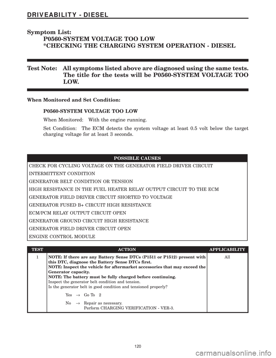
Symptom List:
P0560-SYSTEM VOLTAGE TOO LOW
*CHECKING THE CHARGING SYSTEM OPERATION - DIESEL
Test Note: All symptoms listed above are diagnosed using the same tests.
The title for the tests will be P0560-SYSTEM VOLTAGE TOO
LOW.
When Monitored and Set Condition:
P0560-SYSTEM VOLTAGE TOO LOW
When Monitored: With the engine running.
Set Condition: The ECM detects the system voltage at least 0.5 volt below the target
charging voltage for at least 3 seconds.
POSSIBLE CAUSES
CHECK FOR CYCLING VOLTAGE ON THE GENERATOR FIELD DRIVER CIRCUIT
INTERMITTENT CONDITION
GENERATOR BELT CONDITION OR TENSION
HIGH RESISTANCE IN THE FUEL HEATER RELAY OUTPUT CIRCUIT TO THE ECM
GENERATOR FIELD DRIVER CIRCUIT SHORTED TO VOLTAGE
GENERATOR FUSED B+ CIRCUIT HIGH RESISTANCE
ECM/PCM RELAY OUTPUT CIRCUIT OPEN
GENERATOR GROUND CIRCUIT HIGH RESISTANCE
GENERATOR FIELD DRIVER CIRCUIT OPEN
ENGINE CONTROL MODULE
TEST ACTION APPLICABILITY
1NOTE: If there are any Battery Sense DTCs (P1511 or P1512) present with
this DTC, diagnose the Battery Sense DTCs first.
NOTE: Inspect the vehicle for aftermarket accessories that may exceed the
Generator capacity.
NOTE: The battery must be fully charged before continuing.
Inspect the generator belt condition and tension.
Is the generator belt in good condition and tensioned properly?All
Ye s®Go To 2
No®Repair as necessary.
Perform CHARGING VERIFICATION - VER-3.
120
DRIVEABILITY - DIESEL
Page 1489 of 4284
LUBRICATION & MAINTENANCE
TABLE OF CONTENTS
page page
LUBRICATION & MAINTENANCE
SPECIFICATIONS.........................1
INTERNATIONAL SYMBOLS
DESCRIPTION............................1
PARTS & LUBRICANT RECOMMENDATION
STANDARD PROCEDURE...................2
LUBRICANT CLASSIFICATIONS.............2
PARTS AND LUBRICANT
RECOMMENDATIONS....................2
FLUID TYPES
DESCRIPTION............................3
OPERATION.............................7
FLUID FILL/CHECK LOCATIONS
DESCRIPTION............................7MAINTENANCE SCHEDULES
DESCRIPTION............................7
HOISTING
STANDARD PROCEDURE..................16
HOISTING............................16
JUMP STARTING
STANDARD PROCEDURE..................16
JUMP STARTING.......................16
TOWING
STANDARD PROCEDURE..................17
TOWING RECOMMENDATIONS............17
LUBRICATION &
MAINTENANCE
SPECIFICATIONS
SPECIFICATIONS - FLUID CAPACITIES
DESCRIPTION SPECIFICATION
Fuel Tank 75 L (20 gal.)
Engine Oil* - 2.4L 4.7 L (5.0 qts.)
Engine Oil* - 3.3/3.8L 4.0 L (4.5 qts.)
Cooling System** - 2.4L 10.7 L (11.4 qts.)
Cooling System** -
3.3/3.8L without Rear
Heater12.6 L (13.4 qts.)
Cooling System** -
3.3/3.8L with Rear Heater15.4 L (16.3 qts.)
Automatic Transaxle -
Service Fill3.8 L (4.0 qts.)
Automatic Transaxle -
31TH Overhaul Fill8.6 L (9.1 qts.)
Automatic Transaxle -
41TE Overhaul Fill9.2 L (9.7 qts.)
AWD Power Transfer Unit 1.15 L (2.4 pts.)
Power Steering 1.2 L (2.5 pts.)
AWD Bi-directional
Overrunning Clutch0.575 L (1.22 pts.)
DESCRIPTION SPECIFICATION
AWD Rear Carrier 0.7 L (1.48 pts.)
*(includes oil filter)
**(includes heater and recovery/reserve bottle)
INTERNATIONAL SYMBOLS
DESCRIPTION
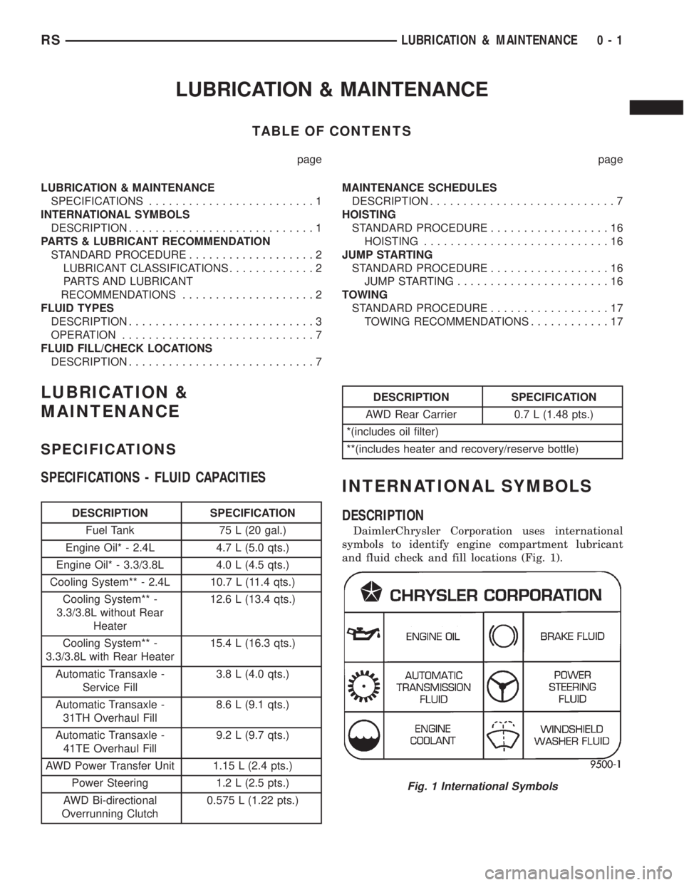
DaimlerChrysler Corporation uses international
symbols to identify engine compartment lubricant
and fluid check and fill locations (Fig. 1).
Fig. 1 International Symbols
RSLUBRICATION & MAINTENANCE0-1
Page 1491 of 4284
FLUID TYPES
DESCRIPTION
E-85 GENERAL INFORMATION
The information in this section is for Flexible Fuel
Vehicles (FFV) only. These vehicles can be identified
by the unique Fuel Filler Door Label that states
Ethanol (E-85) or Unleaded Gasoline Only. This sec-
tion only covers those subjects that are unique to
these vehicles. Please refer to the other sections of
this manual for information on features that are
common between Flexible Fuel and gasoline only
powered vehicles.
ETHANOL FUEL (E-85)
E-85 is a mixture of approximately 85% fuel etha-
nol and 15% unleaded gasoline.
WARNING: Ethanol vapors are extremely flammable
and could cause serious personal injury. Never
have any smoking materials lit in or near the vehi-
cle when removing the fuel filler tube cap (gas cap)
or filling the tank. Do not use E-85 as a cleaning
agent and never use it near an open flame.
FUEL REQUIREMENTS
The vehicle will operate on both unleaded gasoline
with an octane rating of 87, or E-85 fuel, or any mix-
ture of these two.
For best results, a refueling pattern that alternates
between E-85 and unleaded gasoline should be
avoided. When you do switch fuels, it is recom-
mended that
²you do not switch when the fuel gauge indicates
less than 1/4 full
²you do not add less than 5 gallons when refuel-
ing
²you operate the vehicle immediately after refuel-
ing for a period of at least 5 minutes
Observing these precautions will avoid possible
hard starting and/or significant deterioration in
driveability during warm up.
FFV STARTING
The characteristics of E-85 fuel make it unsuitable
for use when ambient temperatures fall below 0ÉF. In
the range of 0ÉF to 32ÉF, you may experience an
increase in the time it takes for your engine to start,
and a deterioration in driveability (sags and/or hesi-
tations) until the engine is fully warmed up.
CRUISING RANGE
Because E-85 fuel contains less energy per gallon
than gasoline, you will experience an increase in fuelconsumption. You can expect your MPG and your
driving range to decrease by about 30% compared to
gasoline operation.
ENGINE OIL
WARNING: NEW OR USED ENGINE OIL CAN BE
IRRITATING TO THE SKIN. AVOID PROLONGED OR
REPEATED SKIN CONTACT WITH ENGINE OIL.
CONTAMINANTS IN USED ENGINE OIL, CAUSED BY
INTERNAL COMBUSTION, CAN BE HAZARDOUS TO
YOUR HEALTH. THOROUGHLY WASH EXPOSED
SKIN WITH SOAP AND WATER. DO NOT WASH
SKIN WITH GASOLINE, DIESEL FUEL, THINNER, OR
SOLVENTS, HEALTH PROBLEMS CAN RESULT. DO
NOT POLLUTE, DISPOSE OF USED ENGINE OIL
PROPERLY. CONTACT YOUR DEALER OR GOVERN-
MENT AGENCY FOR LOCATION OF COLLECTION
CENTER IN YOUR AREA.
API SERVICE GRADE CERTIFIED
Use an engine oil that is API Service Grade Certi-
fied. MOPARtprovides engine oils that conform to
this service grade.
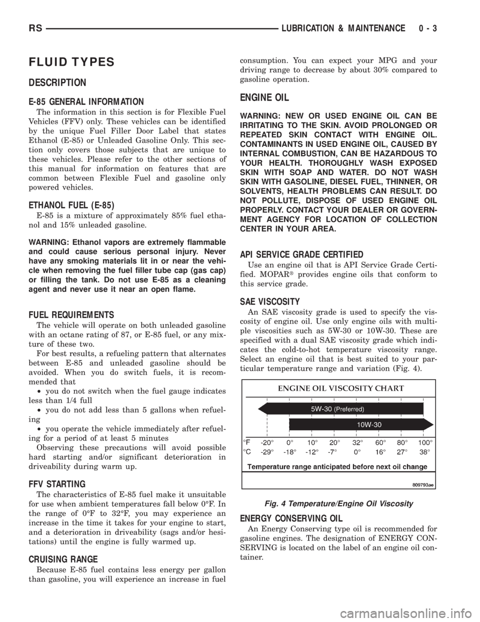
SAE VISCOSITY
An SAE viscosity grade is used to specify the vis-
cosity of engine oil. Use only engine oils with multi-
ple viscosities such as 5W-30 or 10W-30. These are
specified with a dual SAE viscosity grade which indi-
cates the cold-to-hot temperature viscosity range.
Select an engine oil that is best suited to your par-
ticular temperature range and variation (Fig. 4).
ENERGY CONSERVING OIL
An Energy Conserving type oil is recommended for
gasoline engines. The designation of ENERGY CON-
SERVING is located on the label of an engine oil con-
tainer.
Fig. 4 Temperature/Engine Oil Viscosity
RSLUBRICATION & MAINTENANCE0-3