2001 CHRYSLER VOYAGER warning light
[x] Cancel search: warning lightPage 4 of 4284
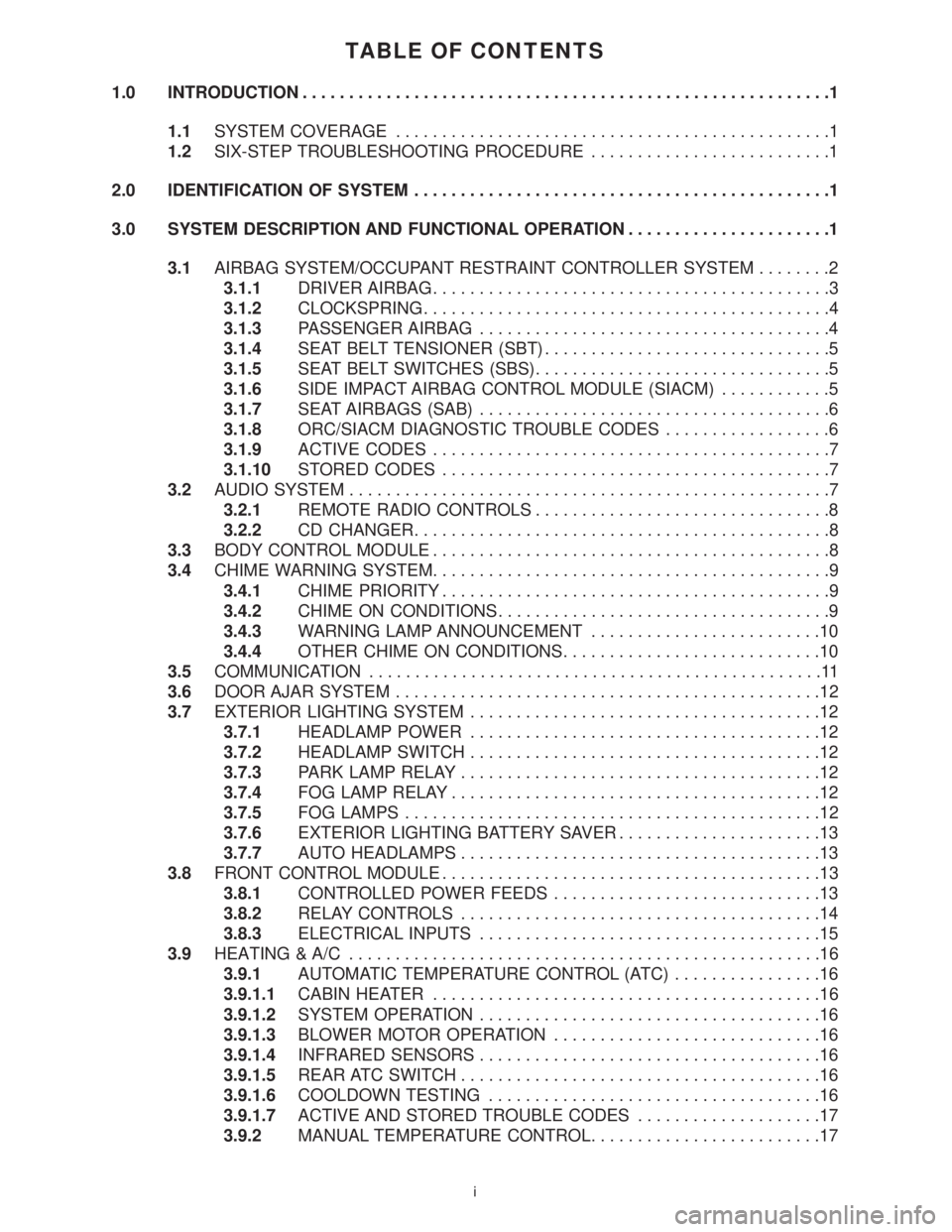
TABLE OF CONTENTS
1.0 INTRODUCTION.........................................................1
1.1SYSTEM COVERAGE...............................................1
1.2SIX-STEP TROUBLESHOOTING PROCEDURE..........................1
2.0 IDENTIFICATION OF SYSTEM.............................................1
3.0 SYSTEM DESCRIPTION AND FUNCTIONAL OPERATION......................1
3.1AIRBAG SYSTEM/OCCUPANT RESTRAINT CONTROLLER SYSTEM........2
3.1.1DRIVER AIRBAG...........................................3
3.1.2CLOCKSPRING............................................4
3.1.3PASSENGER AIRBAG......................................4
3.1.4SEAT BELT TENSIONER (SBT)...............................5
3.1.5SEAT BELT SWITCHES (SBS)................................5
3.1.6SIDE IMPACT AIRBAG CONTROL MODULE (SIACM)............5
3.1.7SEAT AIRBAGS (SAB)......................................6
3.1.8ORC/SIACM DIAGNOSTIC TROUBLE CODES..................6
3.1.9ACTIVE CODES...........................................7
3.1.10STORED CODES..........................................7
3.2AUDIO SYSTEM....................................................7
3.2.1REMOTE RADIO CONTROLS................................8
3.2.2CD CHANGER.............................................8
3.3BODY CONTROL MODULE...........................................8
3.4CHIME WARNING SYSTEM...........................................9
3.4.1CHIME PRIORITY..........................................9
3.4.2CHIME ON CONDITIONS....................................9
3.4.3WARNING LAMP ANNOUNCEMENT.........................10
3.4.4OTHER CHIME ON CONDITIONS............................10
3.5COMMUNICATION.................................................11
3.6DOOR AJAR SYSTEM..............................................12
3.7EXTERIOR LIGHTING SYSTEM......................................12
3.7.1HEADLAMP POWER......................................12
3.7.2HEADLAMP SWITCH......................................12
3.7.3PARK LAMP RELAY.......................................12
3.7.4FOG LAMP RELAY........................................12
3.7.5FOG LAMPS.............................................12
3.7.6EXTERIOR LIGHTING BATTERY SAVER......................13
3.7.7AUTO HEADLAMPS.......................................13
3.8FRONT CONTROL MODULE.........................................13
3.8.1CONTROLLED POWER FEEDS.............................13
3.8.2RELAY CONTROLS.......................................14
3.8.3ELECTRICAL INPUTS.....................................15
3.9HEATING & A/C...................................................16
3.9.1AUTOMATIC TEMPERATURE CONTROL (ATC)................16
3.9.1.1CABIN HEATER..........................................16
3.9.1.2SYSTEM OPERATION.....................................16
3.9.1.3BLOWER MOTOR OPERATION.............................16
3.9.1.4INFRARED SENSORS.....................................16
3.9.1.5REAR ATC SWITCH.......................................16
3.9.1.6COOLDOWN TESTING....................................16
3.9.1.7ACTIVE AND STORED TROUBLE CODES....................17
3.9.2MANUAL TEMPERATURE CONTROL.........................17
i
Page 38 of 4284
This feature dims the interior lighting (courtesy
lamps) gradually if the BCM does not receive any
new inputs that would cause the interior lamps to
remain on.
²PWM Instrument Panel Dimming
²Door Lock Inhibit
This feature disables the door lock functions if the
key is in the ignition and either front door is ajar.
Pressing the RKE lock/unlock button under these
conditions, result in normal lock/unlock activation.
²Power Sliding Door Switch Inputs
The BCM has 4 switch inputs for the power
sliding door feature: Located in the overhead con-
sole are the Left and Right side sliding door
switches to activate either or both sliding doors
under the proper conditions. Also are B-Pillar
switches located on the Left and Right B-pillar
posts.
²Power Liftgate Switch Input
The BCM has 1 Liftgate switch input located in
the overhead console
²Power Lockout Switch Input
The BCM has 1 Lockout switch that when en-
abled will disable the B-Pillar sliding door switches
from activating either sliding door when depressed.
When replacing a body control module there are 2
modules available, a Base and a Midline. The
Midline controller is used on vehicles that have
Power Door Locks. If a vehicle is equipped with the
Vehicle Theft Security System, the midline control-
ler becomes a premium when the theft feature is
enabled.
NOTE: DO NOT SWAP THE BODY CONTROL
MODULE BETWEEN VEHICLES OR BODY
CONTROL MODULES OFF THE SHELF.
Engineering does not recommend that service,
dealers or the plant swap Body Control Modules
(BCM) between vehicles or off the shelf. The BCM
has internal diagnostic capability that assists in
diagnosing the system. When an ªOpenº or a
ªShortº circuit exists, the diagnostic tool can be
used to read the BCM codes. The codes are very
descriptive in identifying the appropriate feature
that has faulted.
3.4 CHIME WARNING SYSTEM
The BCM monitors the door/liftgate ajar
switches, multifunction switches, headlight switch,
ignition switch, PCI bus, and the diagnostic tool to
perform various chime operations. The BCM uses a
low-side driver to control the chime located in the
cluster.
The chime system provides the Driver with warn-
ing chimes for:
²Seat belt
²Exterior lights on
²Key-in Ignition
²Key-in Accessory
²Engine temperature critical
²Low washer fluid
²Turn signals on
²Dome light on
²Low oil pressure
²Any warning lamp announcement
²High-speed warning Gulf Coast Countries (GCC)
only
The output sound intensity of the chime is ap-
proximately 72 decibels.
3.4.1 CHIME PRIORITY
The following list indicates the priority of the
chime when more than one chime is active at the
same time:
²Seat belt warning
²High-speed warning Gulf Coast Countries (GCC)
only
²Turn signal on
²Chime request
²Warning lamp announcement
The cluster is responsible to set priority on all
warning lamp announcement chimes.
3.4.2 CHIME ON CONDITIONS
The following is a list of the chime warnings and
when they will sound.
Driver 's Seat
belt Unbuckled:Sounds for approximately 662
seconds when the igntion is turned
on and driver 's seat belt is not
buckled, as a reminder to the
driver to buckle the seat belt.
Exterior Lights
On:Ignition is in the lock position,
the driver door is ajar, and the
headlight switch is left in any
position, other than auto or off.
The chime will sound as a warn-
ing to the driver until one of the
above conditions is removed or
until the battery protection time
of 3 minutes has expired.
Key-In Ignition: Ignition is in the lock position,
driver door is ajar and the key is
in the ignition. The chime will
sound until one of the above con-
ditions is removed or until the
battery protection time of 15 min-
utes has expired.
9
GENERAL INFORMATION
Page 39 of 4284
Turn Signal On: When the BCM detects a turn
signal input continuously for
1.0mile/0.6km and the vehicle
speed is greater than 15 mph/
24kph, the chime will sound until
the specific turn signal is can-
celled.
Dome Lights On: Ignition is in the lock position,
driver door ajar, and the dome
light switch is left in the on
position. The chime will sound
until one of the above conditions
is removed or until the battery
protection time of 15 minutes has
expired.
Low Oil Pres-
sure:The chime will sound when the
engine is operating and the oil
pressure drops below 4psi/27.5kPa.
Engine
Temperature
Critical:The chime will sound when the
engine is operating and the cool-
ant temperature exceeds 252ÉF/
122Cor 234É/112C(diesel).The
chime is continuous at 257ÉF/
125C and will chime for 4 min-
utes and stop if the temperature
drops below 255ÉF/123C.
Low Washer
FluidThe chime will sound when the
washer fluid drops below a spe-
cific level.
Warning Lamp
Announcement:A chime will sound to alert the
driver to scan the instrument
panel to see which warning lamp
is illuminated. The door/liftgate
ajar warning lamp will appear
without a chime if the vehicle is
running and a door or the liftgate
is opened. A chime will sound if
the door or liftgate is still open
and the vehicle speed is greater
than 4mph/6kph.
High-speed
warning Gulf
Coast Countries
(GCC) onlyThe chime will sound, acting as a
warning to the driver that the
vehicle speed has exceed
75mph62/120kph63.3.4.3 WARNING LAMP ANNOUNCEMENT
Low Fuel Lamp: The cluster will request a single
chime after the indicator is illu-
minated.
Volt Lamp: The cluster will request a single
chime after the indicator is illu-
minated.
Oil Pressure
Lamp:The cluster will request a single
chime after illuminating the in-
dicator above 450rpm vehicle op-
eration.
Headlight Out
Lamp:The cluster will request a single
chime after the indicator is illu-
minated.
Liftgate Ajar
Lamp:The BCM determines when to
chime for liftgate ajar.
Fasten Seat Belt
Lamp:The BCM will request five chimes
from the MIC when the ignition
is turned to the unlock/run/start
positions if the driver seat belt is
not buckled.
Check Engine
Lamp:The cluster will request a single
chime after the indicator is illu-
minated.
Low Washer
Fluid Lamp:The cluster will request a single
chime after the indicator is illu-
minated.
Engine Tempera-
ture Lamp:The cluster will request a single
chime when the indicator is first
illuminated at 252ÉF/122C.
3.4.4 OTHER CHIME ON CONDITIONS
Bulb Check: The chime will sound three times
during bulb check.
Programming of
an Additional
Key Fob:A double cluster chime will sound,
which signals that the program
mode has been initiated.
Programming for
Rolling Door
Locks:When the programming has been
completed, a single tone from the
chime system, will occur.
10
GENERAL INFORMATION
Page 51 of 4284

On vehicles equipped with AutoStick, the display
includes an O/D OFF indicator that is illuminated
when the driver presses the Overdrive Off button
on the transaxle shifter.
3.11.1 INSTRUMENT CLUSTER SELF TEST
1. Depress and hold the Odometer Reset button.
2. Turn the ignition switch to the RUN/START
position.
3. Release the Odometer reset button.
The Instrument Cluster will illuminate all indi-
cators and step the gauges through several calibra-
tion points. Also, the odometer will display any
stored codes that may have set.
3.11.2 MESSAGE CENTER
The Message Center is located above the brow of
the Instrument Cluster. It houses the following
warning indicators: Check Engine/Service Engine
Soon, high beam, left and right turn signals, Secu-
rity Alarm Set, and low oil pressure. On base
models equipped with the three-speed transaxle,
these indicators appear in the face of the cluster.
The Security Alarm set indicator is a red circle.
Activation of Instrument Cluster indicators is
coordinated with indicators in the message center
and EVIC to avoid redundancy. A revised safety
standard now requires that the seat belt warning
lamp in the Instrument Cluster remain lit if the
driver seat belt is not buckled. A headlamp out ISO
indicator has been added to the Instrument Cluster
to alert the driver when a headlamp is not function-
ing.
3.12 INTERIOR LIGHTING
3.12.1 COURTESY LAMP CONTROL
The body controller has direct control over all of
the vehicle's courtesy lamps. The body computer
will illuminate the courtesy lamps under any of the
following conditions:
1. Any door ajar and courtesy lamp switch on the
headlamp switch is not in the dome off position.
2. The courtesy lamp switch on the headlamp
switch is in the dome on position.
3. A Remote Keyless Entry unlock message is re-
ceived.
4. Driver door unlocked with key (with VTSS only).
3.12.2 ILLUMINATED ENTRY
Illuminated entry will be initiated when the cus-
tomer enters the vehicle by unlocking the doors
with the key fob, or with the key if the vehicle is
equipped with vehicle theft alarm. Upon exiting thevehicle, if the lock button is pressed with a door
open, illuminated entry will cancel when the door
closes. If the doors are closed and the ignition
switch is turned on, the illuminated entry also
cancels. The illuminated entry feature will not
operate if the courtesy lamp switch is in the dome
off position.
3.12.3 INTERIOR LIGHTING BATTERY
SAVER
If any of the interior lamps are left on after the
ignition is turned off, the BCM will turn them off
after 8 minutes. To return to normal operation, the
courtesy lamps will operate after the dome lamp
switch or door ajar switch changes state. The glove
box and switched reading lamps require that the
ignition be turned to the on/acc position.
3.13 MEMORY SYSTEM
The memory system consists of power driver 's
seat, power mirrors and radio presets. The Memory
Seat/Mirror Module (MSMM) is located under the
driver 's seat. It receives input from the following:
driver 's manual 8-way seat switch, driver 's seat
position sensors, PCI bus circuits, and the power
mirror sensors. The module uses these inputs to
perform the following functions: position the driv-
er 's memory seat, both exterior mirrors (during
recalls), and send/receive the memory system infor-
mation over the PCI bus.
The Memory Set Switch is wired to the Body
Control Module (BCM). When a button (either #1 or
#2) is pressed on the set switch causes the to BCM
send a message to the MSMM which in turn sends
a motion status messages to the BCM. If the BCM
receives no motion from the MSMM it will send a
recall message to the MSMM and radio (once igni-
tion is in run or accessory). The MSMM will in turn
position the drivers seat, both mirrors along with
recalling the radio presets. If the drivers seat or
either exterior mirror is inoperative from its own
respective switches, use the service information
and schematic to diagnose the problem. This man-
ual addresses the memory problems only and it is
assumed there is not a basic component failure.
3.13.1 POWER SEAT
The memory power seat provides the driver with
2 position settings for the driver 's seat. Each power
seat motor is connected to the MSMM with two
motor drive circuits. Each circuit is switched be-
tween battery and ground. By being able to bi-
directionally drive the circuits, the MSMM controls
the movement of the motors based on input from
the power seat switch or from the position sensors
when performing a memory recall. Each motor
22
GENERAL INFORMATION
Page 57 of 4284
defined as the amount of time from the start of a
wipe to the beginning of the next wipe. The rear
wiper system delay time is based on the following:
7.75 - (MPH x .05) = Seconds delay
Examples:
At zero (0) MPH the delay is 7.75 seconds.
At 100 MPH the delay is 2.75 seconds.
3.21.8 WIPE AFTER WASH
When the driver presses the wash button for over
1.5 seconds and releases it, the wiper will continue
to run for 2 additional wipe cycles.
3.22 USING THE DRBIIIT
Refer to the DRBIIItuser guide for instructions
and assistance with reading trouble codes, erasing
trouble codes, and other DRBIIItfunctions.
3.22.1 DRBIIITERROR MESSAGES
Under normal operation, the DRBIIItwill dis-
play one of only two error messages: user-requested
WARM Boot or User-Requested COLD Boot. If the
DRBIIItshould display any other error message,
record the entire display and call the STAR Center.
This is a sample of such an error message display:
ver:2.14
date: 26 Jul93
file: key_iff.cc
date: Jul26 1993
line: 548
err: 0xi
User-Requested COLD Boot
Press MORE to switch between this display
and the application screen.
Press F4 when done noting information.
3.22.2 DRBIIITDOES NOT POWER UP
(BLANK SCREEN)
If the LED's do not light or no sound is emitted at
start up, check for loose cable connections or a bad
cable. Check the vehicle battery voltage (data link
connector cavity 16). A minimum of 11 volts is
required to adequately power the DRBIIIt. Check
for proper grounds at DLC cavities 4 and 5.
If all connections are proper between the
DRBIIItand the vehicle or other devices, and the
vehicle battery is fully charged, an inoperative
DRBIIItmay be the result or a faulty cable or
vehicle wiring.
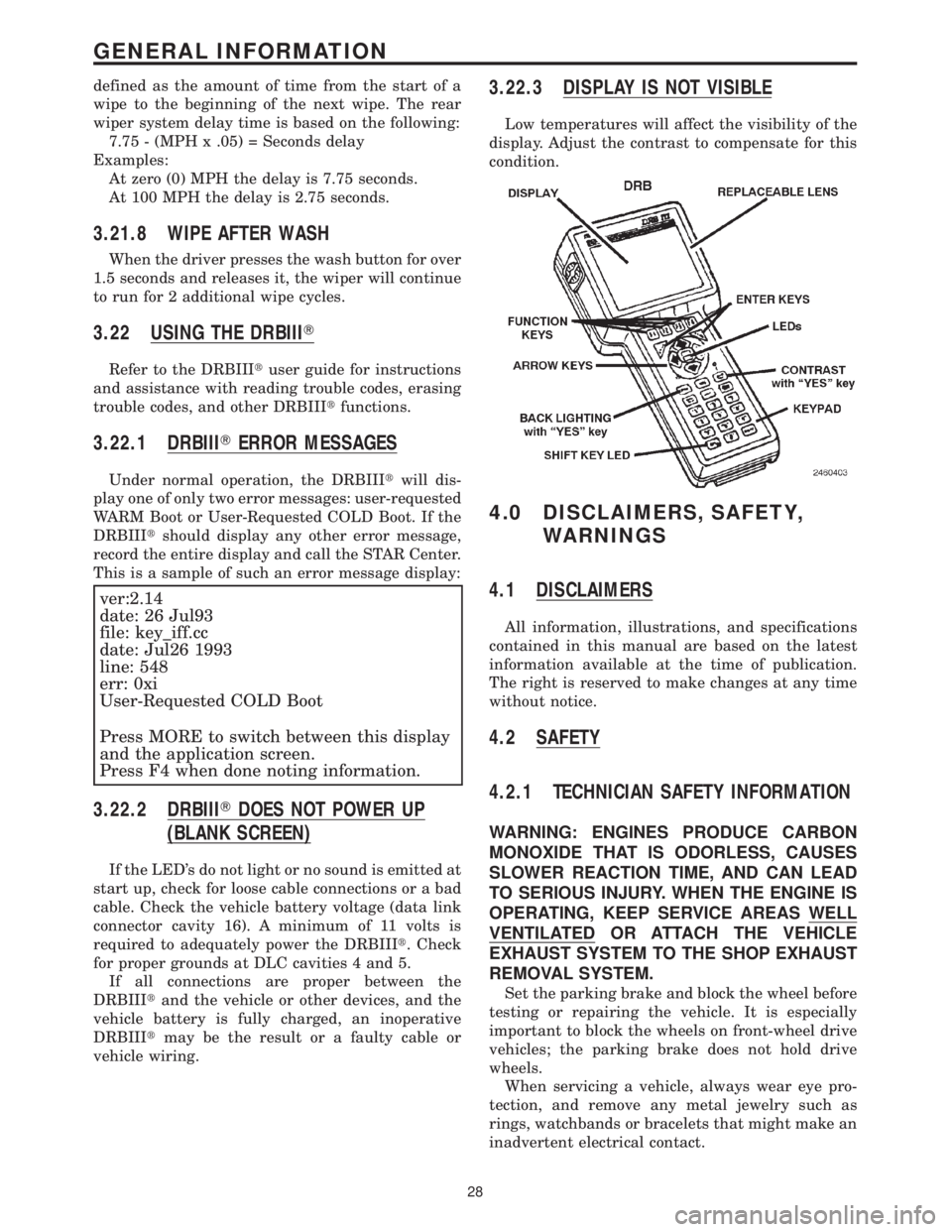
3.22.3 DISPLAY IS NOT VISIBLE
Low temperatures will affect the visibility of the
display. Adjust the contrast to compensate for this
condition.
4.0 DISCLAIMERS, SAFETY,
WARNINGS
4.1 DISCLAIMERS
All information, illustrations, and specifications
contained in this manual are based on the latest
information available at the time of publication.
The right is reserved to make changes at any time
without notice.
4.2 SAFETY
4.2.1 TECHNICIAN SAFETY INFORMATION
WARNING: ENGINES PRODUCE CARBON
MONOXIDE THAT IS ODORLESS, CAUSES
SLOWER REACTION TIME, AND CAN LEAD
TO SERIOUS INJURY. WHEN THE ENGINE IS
OPERATING, KEEP SERVICE AREAS WELL
VENTILATED OR ATTACH THE VEHICLE
EXHAUST SYSTEM TO THE SHOP EXHAUST
REMOVAL SYSTEM.
Set the parking brake and block the wheel before
testing or repairing the vehicle. It is especially
important to block the wheels on front-wheel drive
vehicles; the parking brake does not hold drive
wheels.
When servicing a vehicle, always wear eye pro-
tection, and remove any metal jewelry such as
rings, watchbands or bracelets that might make an
inadvertent electrical contact.
28
GENERAL INFORMATION
Page 59 of 4284
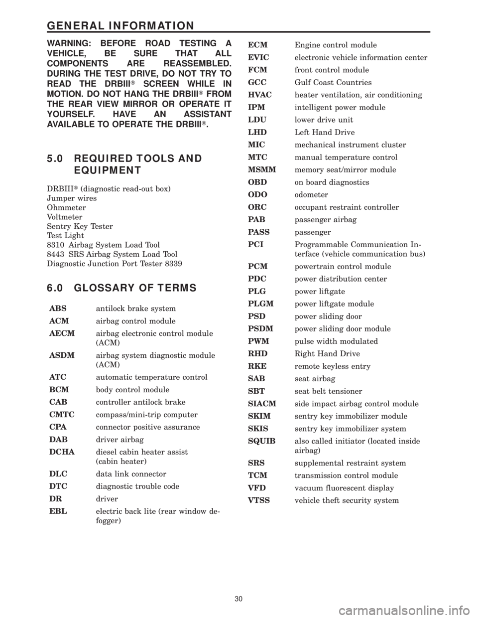
WARNING: BEFORE ROAD TESTING A
VEHICLE, BE SURE THAT ALL
COMPONENTS ARE REASSEMBLED.
DURING THE TEST DRIVE, DO NOT TRY TO
READ THE DRBIIITSCREEN WHILE IN
MOTION. DO NOT HANG THE DRBIIITFROM
THE REAR VIEW MIRROR OR OPERATE IT
YOURSELF. HAVE AN ASSISTANT
AVAILABLE TO OPERATE THE DRBIIIT.
5.0 REQUIRED TOOLS AND
EQUIPMENT
DRBIIIt(diagnostic read-out box)
Jumper wires
Ohmmeter
Voltmeter
Sentry Key Tester
Test Light
8310 Airbag System Load Tool
8443 SRS Airbag System Load Tool
Diagnostic Junction Port Tester 8339
6.0 GLOSSARY OF TERMS
ABSantilock brake system
ACMairbag control module
AECMairbag electronic control module
(ACM)
ASDMairbag system diagnostic module
(ACM)
AT Cautomatic temperature control
BCMbody control module
CABcontroller antilock brake
CMTCcompass/mini-trip computer
CPAconnector positive assurance
DABdriver airbag
DCHAdiesel cabin heater assist
(cabin heater)
DLCdata link connector
DTCdiagnostic trouble code
DRdriver
EBLelectric back lite (rear window de-
fogger)ECMEngine control module
EVICelectronic vehicle information center
FCMfront control module
GCCGulf Coast Countries
HVACheater ventilation, air conditioning
IPMintelligent power module
LDUlower drive unit
LHDLeft Hand Drive
MICmechanical instrument cluster
MTCmanual temperature control
MSMMmemory seat/mirror module
OBDon board diagnostics
ODOodometer
ORCoccupant restraint controller
PA Bpassenger airbag
PASSpassenger
PCIProgrammable Communication In-
terface (vehicle communication bus)
PCMpowertrain control module
PDCpower distribution center
PLGpower liftgate
PLGMpower liftgate module
PSDpower sliding door
PSDMpower sliding door module
PWMpulse width modulated
RHDRight Hand Drive
RKEremote keyless entry
SABseat airbag
SBTseat belt tensioner
SIACMside impact airbag control module
SKIMsentry key immobilizer module
SKISsentry key immobilizer system
SQUIBalso called initiator (located inside
airbag)
SRSsupplemental restraint system
TCMtransmission control module
VFDvacuum fluorescent display
VTSSvehicle theft security system
30
GENERAL INFORMATION
Page 63 of 4284
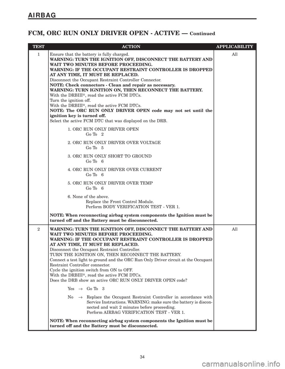
TEST ACTION APPLICABILITY
1 Ensure that the battery is fully charged.
WARNING: TURN THE IGNITION OFF, DISCONNECT THE BATTERY AND
WAIT TWO MINUTES BEFORE PROCEEDING.
WARNING: IF THE OCCUPANT RESTRAINT CONTROLLER IS DROPPED
AT ANY TIME, IT MUST BE REPLACED.
Disconnect the Occupant Restraint Controller Connector.
NOTE: Check connectors - Clean and repair as necessary.
WARNING: TURN IGNITION ON, THEN RECONNECT THE BATTERY.
With the DRBIIIt, read the active FCM DTCs.
Turn the ignition off.
With the DRBIIIt, read the active FCM DTCs.
NOTE: The ORC RUN ONLY DRIVER OPEN code may not set until the
ignition key is turned off.
Select the active FCM DTC that was displayed on the DRB.All
1. ORC RUN ONLY DRIVER OPEN
Go To 2
2. ORC RUN ONLY DRIVER OVER VOLTAGE
Go To 5
3. ORC RUN ONLY SHORT TO GROUND
Go To 6
4. ORC RUN ONLY DRIVER OVER CURRENT
Go To 6
5. ORC RUN ONLY DRIVER OVER TEMP
Go To 6
6. None of the above.
Replace the Front Control Module.
Perform BODY VERIFICATION TEST - VER 1.
NOTE: When reconnecting airbag system components the Ignition must be
turned off and the Battery must be disconnected.
2WARNING: TURN THE IGNITION OFF, DISCONNECT THE BATTERY AND
WAIT TWO MINUTES BEFORE PROCEEDING.
WARNING: IF THE OCCUPANT RESTRAINT CONTROLLER IS DROPPED
AT ANY TIME, IT MUST BE REPLACED.
Disconnect the Occupant Restraint Controller.
TURN THE IGNITION ON, THEN RECONNECT THE BATTERY.
Connect a test light to ground and the ORC Run Only Driver circuit at the Occupant
Restraint Controller connector.
Cycle the ignition switch from ON to OFF.
With the DRBIIIt, read the active FCM DTCs.
Does the DRB show an active ORC RUN ONLY DRIVER OPEN code?All
Ye s®Go To 3
No®Replace the Occupant Restraint Controller in accordance with
Service Instructions. WARNING: make sure the battery is discon-
nected and wait 2 minutes before proceeding.
Perform AIRBAG VERIFICATION TEST - VER 1.
NOTE: When reconnecting airbag system components the Ignition must be
turned off and the Battery must be disconnected.
34
AIRBAG
FCM, ORC RUN ONLY DRIVER OPEN - ACTIVE ÐContinued
Page 72 of 4284

TEST ACTION APPLICABILITY
1 Ensure that the battery is fully charged.
WARNING: TURN THE IGNITION OFF, DISCONNECT THE BATTERY AND
WAIT TWO MINUTES BEFORE PROCEEDING.
WARNING: IF THE OCCUPANT RESTRAINT CONTROLLER IS DROPPED
AT ANY TIME, IT MUST BE REPLACED.
Disconnect the Occupant Restraint Controller Connector.
NOTE: Check connectors - Clean and repair as necessary.
WARNING: TURN IGNITION ON, THEN RECONNECT THE BATTERY.
With the DRBIIIt, read the active FCM DTCs.
Turn the ignition off.
With the DRBIIIt, read the active FCM DTCs.
NOTE: The ORC RUN-START DRIVER OPEN code may not set until the
ignition key is turned off.
Select the active FCM DTC displayed on the DRB.All
1. ORC RUN-START DRIVER OPEN
Go To 2
2. ORC RUN-START DRIVER OVER VOLTAGE
Go To 5
3. ORC RUN-START SHORT TO GROUND
Go To 6
4. ORC RUN-START DRIVER OVER CURRENT
Go To 6
5. ORC RUN-START DRIVER OVER TEMP
Go To 6
6. None of the above.
Replace the Front Control Module.
Perform BODY VERIFICATION TEST - VER 1.
NOTE: When reconnecting airbag system components the Ignition must be
turned off and the Battery must be disconnected.
2WARNING: TURN THE IGNITION OFF, DISCONNECT THE BATTERY AND
WAIT TWO MINUTES BEFORE PROCEEDING.
WARNING: IF THE OCCUPANT RESTRAINT CONTROLLER IS DROPPED
AT ANY TIME, IT MUST BE REPLACED.
Disconnect the Occupant Restraint Controller.
TURN THE IGNITION ON, THEN RECONNECT THE BATTERY.
Connect a test light to ground and the ORC Run-Start Driver circuit at the ORC
connector.
Cycle the ignition switch from ON to OFF.
With the DRBIIIt, read the active FCM DTCs.
Does the DRB show an active ORC RUN-START DRIVER OPEN code?All
Ye s®Go To 3
No®Replace the Occupant Restraint Controller in accordance with
Service Instructions. WARNING: make sure the battery is discon-
nected and wait 2 minutes before proceeding.
Perform AIRBAG VERIFICATION TEST - VER 1.
NOTE: When reconnecting airbag system components the Ignition must be
turned off and the Battery must be disconnected.
43
AIRBAG
FCM, ORC RUN-START DRIVER OPEN - ACTIVE ÐContinued