2001 CHRYSLER VOYAGER fuse
[x] Cancel search: fusePage 25 of 4284
TABLE OF CONTENTS - Continued
LEFT REMOTE RADIO SWITCH - BLACK 2 WAY...........................1053
LEFT SEAT AIRBAG - YELLOW 2 WAY...................................1053
LEFT SIDE IMPACT AIRBAG CONTROL MODULE - YELLOW/RED 7 WAY......1053
LEFT SLIDING DOOR CONTROL MODULE C1 (POWER SLIDING DOOR) -
BLACK 8 WAY........................................................1053
LEFT SLIDING DOOR CONTROL MODULE C2 (POWER SLIDING DOOR) -
BLACK/RED 20 WAY..................................................1054
LEFT SLIDING DOOR LATCH SENSING SWITCH (POWER SLIDING DOOR) -
BLACK 6 WAY........................................................1054
LEFT SLIDING DOOR LOCK MOTOR (POWER SLIDING DOOR) - BLACK 4
WAY................................................................1054
LEFT SLIDING DOOR LOCK MOTOR/AJAR SWITCH (MANUAL
SLIDING DOOR) - BLACK 4 WAY........................................1055
LEFT SLIDING DOOR MOTOR (POWER SLIDING DOOR) - BLACK 8 WAY.....1055
LEFT STOP/TURN SIGNAL RELAY (TRAILER TOW) - BLACK 5 WAY..........1055
LEFT VISOR/VANITY LAMP (PREMIUM/LUXURY) - BLACK 2 WAY............1055
LICENSE LAMP (POWER LIFTGATE) - DK. GRAY 8 WAY....................1056
LICENSE LAMP (POWER RELEASE) - DK. GRAY 4 WAY....................1056
LIFTGATE AJAR SWITCH (MANUAL RELEASE) - BLACK 2 WAY..............1056
LIFTGATE AJAR SWITCH (POWER RELEASE) - BLACK 4 WAY..............1056
LIFTGATE CINCH/RELEASE MOTOR (POWER LIFTGATE) - BLUE 7 WAY......1057
LIFTGATE CYLINDER LOCK SWITCH - BLACK 2 WAY......................1057
LIFTGATE LEFT PINCH SENSOR (POWER LIFTGATE) - BLACK 2 WAY........1057
LIFTGATE RIGHT PINCH SENSOR (POWER LIFTGATE) - BLACK 2 WAY......1057
MEMORY POWER SEAT SWITCH - GREEN 10 WAY........................1058
MEMORY SEAT FRONT VERTICAL MOTOR - RED 2 WAY...................1058
MEMORY SEAT FRONT VERTICAL POSITION SENSOR - BLACK 3 WAY......1058
MEMORY SEAT HORIZONTAL MOTOR - BLACK 2 WAY.....................1058
MEMORY SEAT HORIZONTAL POSITION SENSOR - BLACK 3 WAY...........1058
MEMORY SEAT REAR VERTICAL MOTOR - RED 2 WAY....................1059
MEMORY SEAT REAR VERTICAL POSITION SENSOR - BLACK 3 WAY........1059
MEMORY SEAT RECLINER MOTOR - GREEN 2 WAY.......................1059
MEMORY SEAT RECLINER POSITION SENSOR - BLACK 3 WAY.............1059
MEMORY SEAT SWITCH - BLACK 2 WAY.................................1059
MEMORY SEAT/MIRROR MODULE C1 - GRAY 2 WAY......................1060
MEMORY SEAT/MIRROR MODULE C2 - GRAY 26 WAY.....................1060
MEMORY SEAT/MIRROR MODULE C3 - GRAY 16 WAY.....................1060
MEMORY SEAT/MIRROR MODULE C4 - WHITE 12 WAY....................1061
MODE DOOR ACTUATOR (ATC) - GRAY 2 WAY...........................1061
MODE DOOR ACTUATOR (MTC) - GRAY 2 WAY...........................1061
MULTI-FUNCTION SWITCH - BLACK 4 WAY...............................1061
OCCUPANT RESTRAINT CONTROLLER - YELLOW/RED 23 WAY.............1062
OVERHEAD CONSOLE (EXCEPT BASE) - BLACK 12 WAY..................1062
PASSENGER AIRBAG - YELLOW 4 WAY..................................1063
PASSENGER BLEND DOOR ACTUATOR (ATC) - GRAY 2 WAY...............1063
PASSENGER BLEND DOOR ACTUATOR (MTC) - GRAY 2 WAY...............1063
PASSENGER DOOR LOCK SWITCH - BLACK 3 WAY.......................1063
PASSENGER FOLDING MIRROR RELAY (BUILT-UP-EXPORT) - BLUE 9 WAY . .1064
PASSENGER SEAT BELT SWITCH-2WAY...............................1064
PASSENGER SEAT BELT TENSIONER-2WAY............................1064
FUSES (IPM).........................................................1066
ACCESSORY RELAY..................................................1066
DEFOGGER RELAY...................................................1066
xxii
Page 41 of 4284
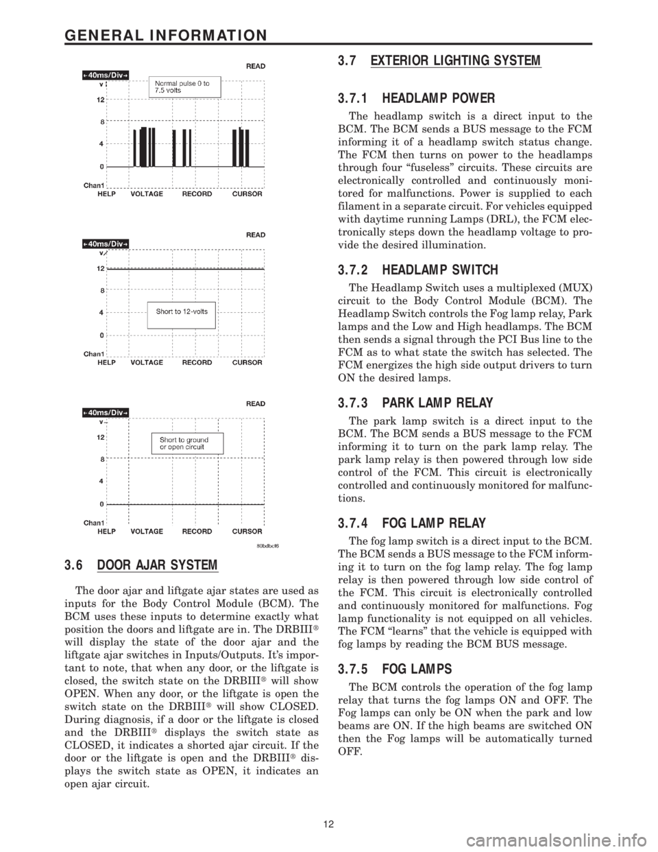
3.6 DOOR AJAR SYSTEM
The door ajar and liftgate ajar states are used as
inputs for the Body Control Module (BCM). The
BCM uses these inputs to determine exactly what
position the doors and liftgate are in. The DRBIIIt
will display the state of the door ajar and the
liftgate ajar switches in Inputs/Outputs. It's impor-
tant to note, that when any door, or the liftgate is
closed, the switch state on the DRBIIItwill show
OPEN. When any door, or the liftgate is open the
switch state on the DRBIIItwill show CLOSED.
During diagnosis, if a door or the liftgate is closed
and the DRBIIItdisplays the switch state as
CLOSED, it indicates a shorted ajar circuit. If the
door or the liftgate is open and the DRBIIItdis-
plays the switch state as OPEN, it indicates an
open ajar circuit.
3.7 EXTERIOR LIGHTING SYSTEM
3.7.1 HEADLAMP POWER
The headlamp switch is a direct input to the
BCM. The BCM sends a BUS message to the FCM
informing it of a headlamp switch status change.
The FCM then turns on power to the headlamps
through four ªfuselessº circuits. These circuits are
electronically controlled and continuously moni-
tored for malfunctions. Power is supplied to each
filament in a separate circuit. For vehicles equipped
with daytime running Lamps (DRL), the FCM elec-
tronically steps down the headlamp voltage to pro-
vide the desired illumination.
3.7.2 HEADLAMP SWITCH
The Headlamp Switch uses a multiplexed (MUX)
circuit to the Body Control Module (BCM). The
Headlamp Switch controls the Fog lamp relay, Park
lamps and the Low and High headlamps. The BCM
then sends a signal through the PCI Bus line to the
FCM as to what state the switch has selected. The
FCM energizes the high side output drivers to turn
ON the desired lamps.
3.7.3 PARK LAMP RELAY
The park lamp switch is a direct input to the
BCM. The BCM sends a BUS message to the FCM
informing it to turn on the park lamp relay. The
park lamp relay is then powered through low side
control of the FCM. This circuit is electronically
controlled and continuously monitored for malfunc-
tions.
3.7.4 FOG LAMP RELAY
The fog lamp switch is a direct input to the BCM.
The BCM sends a BUS message to the FCM inform-
ing it to turn on the fog lamp relay. The fog lamp
relay is then powered through low side control of
the FCM. This circuit is electronically controlled
and continuously monitored for malfunctions. Fog
lamp functionality is not equipped on all vehicles.
The FCM ªlearnsº that the vehicle is equipped with
fog lamps by reading the BCM BUS message.
3.7.5 FOG LAMPS
The BCM controls the operation of the fog lamp
relay that turns the fog lamps ON and OFF. The
Fog lamps can only be ON when the park and low
beams are ON. If the high beams are switched ON
then the Fog lamps will be automatically turned
OFF.
12
GENERAL INFORMATION
Page 42 of 4284
3.7.6 EXTERIOR LIGHTING BATTERY
SAVER
The BCM monitors the status of, and controls, the
Park Lamps, Headlamps and Fog Lamp relays. If
any exterior lamps are left ON after the ignition is
turned OFF, the BCM will turn them OFF after 3
minutes.
3.7.7 AUTO HEADLAMPS
This feature is available on vehicles equipped
with both the Electrocromatic Mirror (ECM) and
the Compass/Mini-Trip Computer (CMTC). When
the BCM detects a day/night signal from the CMTC,
an ECM is present and Auto Headlamp mode is
selected.
3.8 FRONT CONTROL MODULE
The Front Control Module (FCM) is an electrical
control and interface center located in the engine
compartment. When it is mated to the Power Dis-
tribution Center (PDC), it is referred to as the
Intelligent Power Module (IPM). The IPM, with its
fuses and relays provides power and signal distri-
bution throughout most of the vehicle. The FCM
receives both hard wire and digital electronic inputs
from the vehicle electrical system through the PDC.
Based on these inputs and the ignition switch
position, it provides direct power feeds and relay
control to some of the vehicles' most critical electri-
cal systems.
The Front Control Module provides the following
features:
Controlled power feeds:
²Front airbag system
²Side airbag system
²Headlamp power
²EATX module power (4 speed only)
²Front washer motor
²Rear washer motor
²Brake shift interlock system
Relay controls:
²Fog lamp relay (when equipped)
²Park lamp relay
²Front wiper on relay
²Front wiper high/low relay
²Accessory relay
²Horn relay
²Front & rear blower relay
²Name brand speakers (NBS) relay
²Electronic back light (EBL) run only relay
²Cabin heater relayElectrical inputs:
²Headlamp battery supplies1&2
²Module battery supply
²Power ground
²Ignition switch RUN or START position status
²Ignition switch START only status
²PCI Bus
²Stop lamp switch
²Horn switch
²Back-up switch
²Wiper park switch
²Washer fluid level switch
²Brake fluid level switch
²Ambient temperature sensor
²Right park lamp outage
²Left park lamp outage
²Battery IOD
²Battery (+) connection detection
²Flash reprogramming voltage
3.8.1 CONTROLLED POWER FEEDS
Front airbag system
The FCM provides power to the Occupant Re-
straint Control (ORC) system through two ªfuse-
lessº circuits (ORC RUN/START, and ORC RUN
only). These circuits are electronically controlled
and continuously monitored for malfunctions.
Power is supplied while the ignition switch is in the
RUN and START positions on pin 48 of the FCM
connector, and in the RUN only position on pin 29.
Side airbag system
The FCM provides power to the Side Impact
Airbag Control Module (SIACM) system through
one ªfuselessº circuit. This circuit is electronically
controlled and continuously monitored for malfunc-
tions. Power is supplied in the ignition RUN and
START positions on pin 28 of the FCM connector.
Headlamp power
The headlamp switch is a direct input to the
BCM. The BCM sends a PCI Bus message to the
FCM informing it of a headlamp switch status
change. The FCM then turns on power to the
headlamps through four ªfuselessº circuits. These
circuits are electronically controlled and continu-
ously monitored for malfunctions. Power is supplied
to each filament in a separate circuit (RH low on pin
6, RH high on pin 4, LH low on pin 3 and LH high
on pin 5). For vehicles equipped with Daytime
Running Lamps (DRL), the FCM electronically
steps down the headlamp voltage to provide the
desired illumination.
13
GENERAL INFORMATION
Page 55 of 4284

manual sliding door. When the child lock out switch
is on, the B pillar switches are disabled.
There is only one part number for the power
sliding door module (PSDM). The driver sliding
door harness has an additional ground circuit which
will identify it as the driver side. This eliminates
the need for a left and a right side module.
3.18.2 DIAGNOSTIC FEATURES
The PSDM can be flashed on vehicle via PCI bus
with a DRBIIItdiagnostic tool. The DRBIIItcan
read all inputs, actuate all outputs, read module
information, and read diagnostic trouble codes. As a
reminder, some DTC's can be set during normal
PSD operation.
3.18.3 SYSTEM INHIBITORS
1. Battery voltage too high or too low (above 16V,
below 9.5V)
2. Vehicle in gear
3. Vehicle speed > 0 mph/km/h
4. Child locks enabled inhibit the B pillar switch
operation
5. O/H console lockout will inhibit the B pillar
switches
6. Doors locked will inhibit all interior switches
from opening (Overhead Console, B Pillar). A
locked sliding door can be power closed.
3.19 REAR WINDOW DEFOG/HEATED
MIRROR/FRONT WIPER DE-ICE
The defroster button located on the HVAC control
controls the rear window defogger, heated side view
mirrors and front wiper de-icer grid. In addition the
front wiper de-ice function is turned on when front
defog/defrost mode is selected.
When the defroster button is pushed, the HVAC
control sends a bus message over the PCI bus to the
Front Control Module (FCM) which controls the
Rear Window Defogger relay. The defroster LED
will illuminate when the defroster function is on.
The defroster will function for 10 minutes or can be
cycled off sooner by pressing the defroster button
again. The front wiper de-icer grid receives its 12
volts from the accessory relay through fuse 11 and
the HVAC control module supplies the grid ground.
3.20 VEHICLE THEFT SECURITY SYSTEM
3.20.1 BASE ALARM SYSTEM
The Vehicle Theft Security System (VTSS) is part
of the Body Control Module (BCM). The BCM
monitors the vehicle doors, liftgate, hood, and theignition for unauthorized operation. The alarm ac-
tivates by sounding the horn, flashing the head-
lamps and the VTSS indicator lamp. The VTSS does
not prevent engine operation, this is done with the
Sentry Key Immobilizer Module (SKIM). Passive
arming occurs in one of two ways. Upon normal
vehicle exit by removing the ignition key, opening
the driver door, locking the doors with the power
lock, and closing the driver door, or by removing the
ignition key, opening the driver door, closing the
driver door, and locking the doors with the Remote
Keyless Entry (RKE) transmitter. The VTSS indi-
cator lamp will flash for approximately 15 seconds
during the arming process. If there is no interrup-
tion during the arming process, upon completion
the VTSS indicator lamp will flash at a slower rate.
When the BCM receives an input to trigger the
alarm, the BCM will control the outputs of the
headlamps, horn, and VTSS lamp for approxi-
mately 18 minutes.
Arming (Active and Passive)
Active arming occurs when the RKE transmitter
is used to lock the vehicle doors, whether the doors
are open or closed. The arming process is complete
only after all doors are closed.
Passive arming occurs when the ignition key is
removed, the driver door is opened, and the doors
are locked with the power door lock switch, and the
door is closed.
Disarming (Active and Passive)
Active disarming occurs when the RKE transmit-
ter is used to unlock the vehicle doors. This disarm-
ing will also halt the alarm once it has been acti-
vated.
Passive disarming occurs upon normal vehicle
entry (unlocking driver door with the key). This
disarming will also halt the alarm once it has been
activated.
Tamper Alert
The VTSS tamper alert will sound the horn three
times upon disarming to indicate a tamper condi-
tion has occurred.
Manual Override
The system will not arm if the doors are locked
using the manual lock control or if the locks are
actuated by an inside occupant after the doors are
closed.
Diagnosis
For complaints about the Vehicle Theft Alarm
triggering on its own, use the DRBIIItand read the
Last VTSS Cause status.
26
GENERAL INFORMATION
Page 58 of 4284
When diagnosing a chassis system problem, it is
important to follow approved procedures where
applicable. These procedures can be found in this
General Information Section or in the service man-
ual procedures. Following these procedures is very
important to safety of individuals performing diag-
nostic tests.
4.2.2 VEHICLE PREPARATION FOR
TESTING
Make sure the vehicle being tested has a fully
charged battery. If it does not, false diagnostic codes
or error messages may occur.
4.2.3 SERVICING SUB-ASSEMBLIES
Some components of the chassis system are in-
tended to be serviced as an assembly only. Attempt-
ing to remove or repair certain system sub-
components may result in personal injury and/or
improper system operation. Only those components
with approved repair and installation procedures in
the service manual should be serviced.
4.2.4 DRBIIITSAFETY INFORMATION
WARNING: EXCEEDING THE LIMITS OF THE
DRBIIITMULTIMETER IS DANGEROUS. IT
CAN EXPOSE YOU TO SERIOUS OR
POSSIBLY FATAL INJURY. CAREFULLY
READ AND UNDERSTAND THE CAUTIONS
AND THE SPECIFICATION LIMITS.
²Follow the vehicle manufacturer 's service speci-
fications at all times.
²Do not use the DRBIIItif it has been damaged.
²Do not use the test leads if the insulation is
damaged or if metal is exposed.
²To avoid electrical shock, do not touch the test
leads, tips, or the circuit being tested.
²Choose the proper range and functions for the
measurement. Do not try voltage or current mea-
surement that may exceed the rated capacity.
²Do not exceed the limits shown in the table below:
FUNCTION INPUT LIMIT
Volts 0 - 500 peak volts AC
0 - 500 volts DC
Ohms (resistance)* 0 -1.12 megohms
Frequency Measured
Frequency Generated0-10kHz
Temperature -58 - 1100ÉF
-50 - 600ÉC* Ohms cannot be measured if voltage is present.
Ohms can be measured only in a non-powered
circuit.
²Voltage between any terminal and ground must
not exceed 500v DC or 500v peak AC.
²Use caution when measuring voltage above 25v
DC or 25v AC.
²Use the low current shunt to measure circuits up
to 10A. Use the high current clamp to measure
circuits exceeding 10A.
²When testing for the presence of voltage or cur-
rent, make sure the meter is functioning cor-
rectly. Take a reading of a known voltage or
current before accepting a zero reading.
²When measuring current, connect the meter in
series with the load.
²Disconnect the live test lead before disconnecting
the common test lead.
²When using the meter function, keep the
DRBIIItaway from spark plug or coil wires to
avoid measuring error from outside interference.
4.3 WARNINGS
4.3.1 VEHICLE DAMAGE WARNINGS
Before disconnecting any control module, make
sure the ignition is ªoffº. Failure to do so could
damage the module.
When testing voltage or continuity at any control
module, use the terminal side (not the wire end) of
the connector. Do not probe a wire through the
insulation; this will damage it and eventually cause
it to fail because of corrosion. Be careful when
performing electrical tests so as to prevent acciden-
tal shorting of terminals. Such mistakes can dam-
age fuses or components. Also, a second code could
be set, making diagnosis of the original problem
more difficult.
4.3.2 ROAD TESTING A COMPLAINT
VEHICLE
Some complaints will require a test drive as part
of the repair verification procedure. The purpose of
the test drive is to try to duplicate the diagnostic
code or symptom condition.
29
GENERAL INFORMATION
Page 218 of 4284
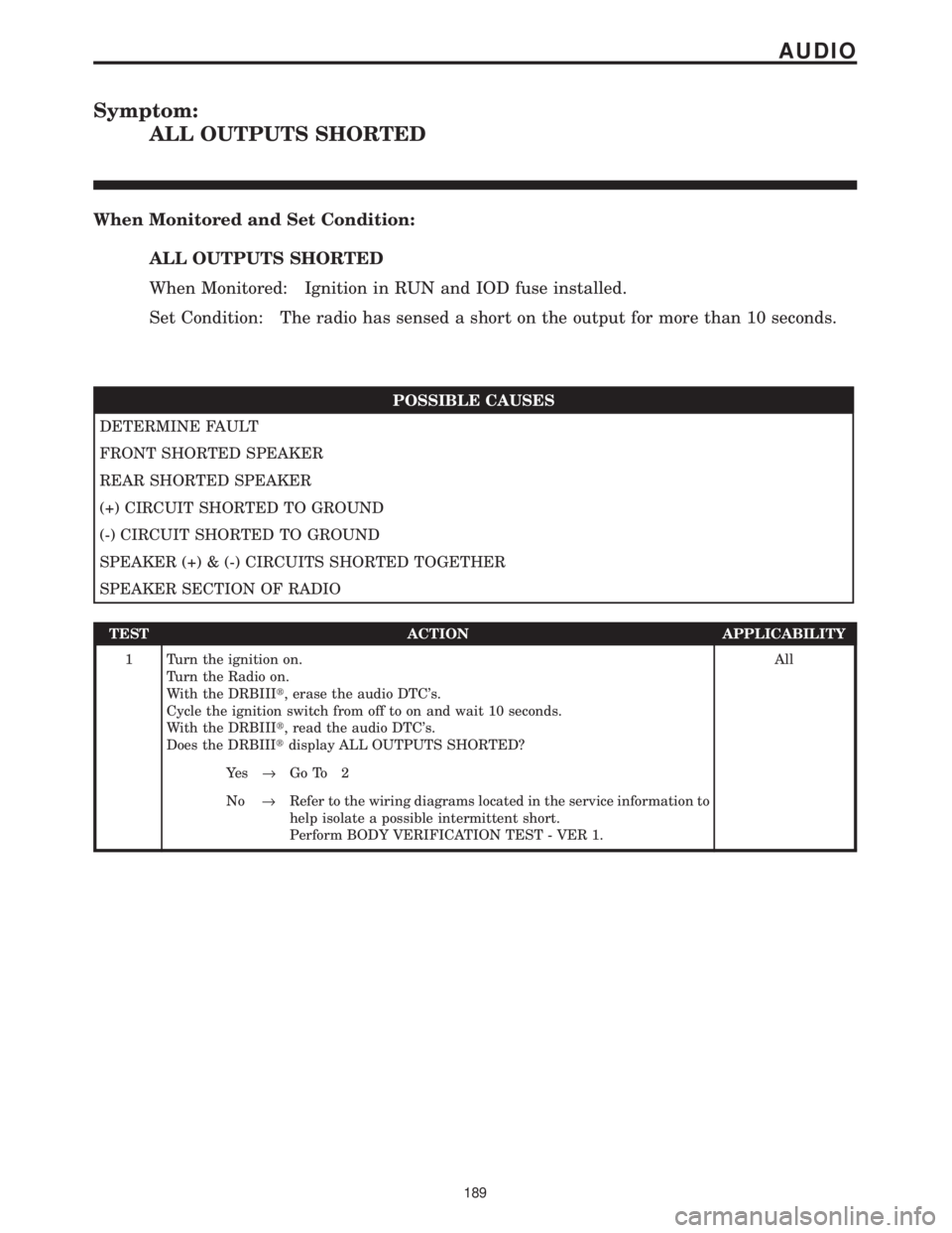
Symptom:
ALL OUTPUTS SHORTED
When Monitored and Set Condition:
ALL OUTPUTS SHORTED
When Monitored: Ignition in RUN and IOD fuse installed.
Set Condition: The radio has sensed a short on the output for more than 10 seconds.
POSSIBLE CAUSES
DETERMINE FAULT
FRONT SHORTED SPEAKER
REAR SHORTED SPEAKER
(+) CIRCUIT SHORTED TO GROUND
(-) CIRCUIT SHORTED TO GROUND
SPEAKER (+) & (-) CIRCUITS SHORTED TOGETHER
SPEAKER SECTION OF RADIO
TEST ACTION APPLICABILITY
1 Turn the ignition on.
Turn the Radio on.
With the DRBIIIt, erase the audio DTC's.
Cycle the ignition switch from off to on and wait 10 seconds.
With the DRBIIIt, read the audio DTC's.
Does the DRBIIItdisplay ALL OUTPUTS SHORTED?All
Ye s®Go To 2
No®Refer to the wiring diagrams located in the service information to
help isolate a possible intermittent short.
Perform BODY VERIFICATION TEST - VER 1.
189
AUDIO
Page 230 of 4284
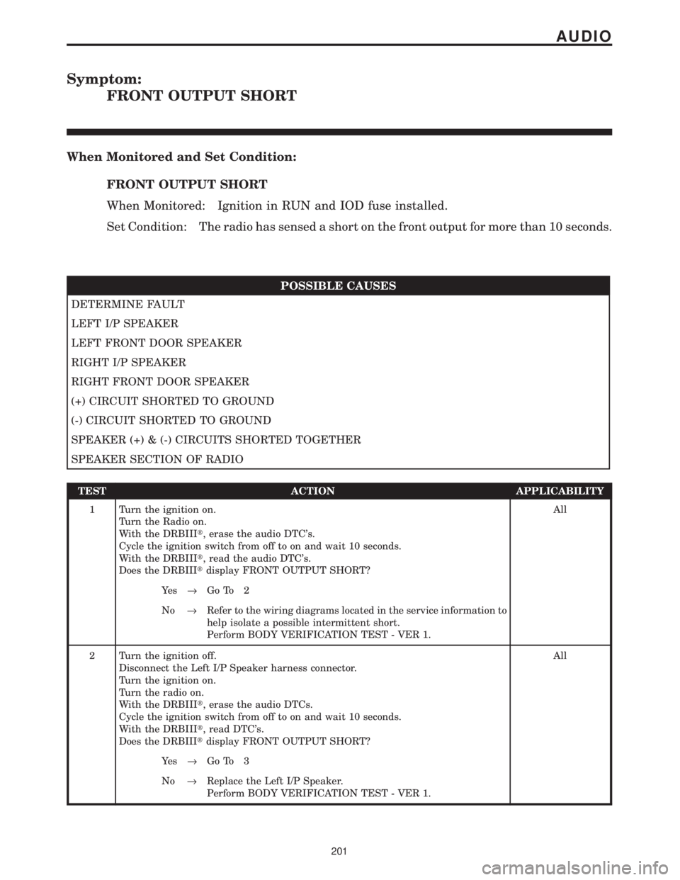
Symptom:
FRONT OUTPUT SHORT
When Monitored and Set Condition:
FRONT OUTPUT SHORT
When Monitored: Ignition in RUN and IOD fuse installed.
Set Condition: The radio has sensed a short on the front output for more than 10 seconds.
POSSIBLE CAUSES
DETERMINE FAULT
LEFT I/P SPEAKER
LEFT FRONT DOOR SPEAKER
RIGHT I/P SPEAKER
RIGHT FRONT DOOR SPEAKER
(+) CIRCUIT SHORTED TO GROUND
(-) CIRCUIT SHORTED TO GROUND
SPEAKER (+) & (-) CIRCUITS SHORTED TOGETHER
SPEAKER SECTION OF RADIO
TEST ACTION APPLICABILITY
1 Turn the ignition on.
Turn the Radio on.
With the DRBIIIt, erase the audio DTC's.
Cycle the ignition switch from off to on and wait 10 seconds.
With the DRBIIIt, read the audio DTC's.
Does the DRBIIItdisplay FRONT OUTPUT SHORT?All
Ye s®Go To 2
No®Refer to the wiring diagrams located in the service information to
help isolate a possible intermittent short.
Perform BODY VERIFICATION TEST - VER 1.
2 Turn the ignition off.
Disconnect the Left I/P Speaker harness connector.
Turn the ignition on.
Turn the radio on.
With the DRBIIIt, erase the audio DTCs.
Cycle the ignition switch from off to on and wait 10 seconds.
With the DRBIIIt, read DTC's.
Does the DRBIIItdisplay FRONT OUTPUT SHORT?All
Ye s®Go To 3
No®Replace the Left I/P Speaker.
Perform BODY VERIFICATION TEST - VER 1.
201
AUDIO
Page 233 of 4284

Symptom:
LEFT OUTPUT SHORT
When Monitored and Set Condition:
LEFT OUTPUT SHORT
When Monitored: Ignition in RUN and IOD fuse installed.
Set Condition: The radio has sensed a short on the left output for more than 10 seconds.
POSSIBLE CAUSES
DETERMINE FAULT
LEFT I/P SPEAKER
LEFT FRONT DOOR SPEAKER
LEFT REAR PILLAR SPEAKER
LEFT REAR SPEAKER
(+) CIRCUIT SHORTED TO GROUND
(-) CIRCUIT SHORTED TO GROUND
SPEAKER (+) & (-) CIRCUITS SHORTED TOGETHER
SPEAKER SECTION OF RADIO
TEST ACTION APPLICABILITY
1 Turn the ignition on.
Turn the Radio on.
With the DRBIIIt, erase the audio DTC's.
Cycle the ignition switch from off to on and wait 10 seconds.
With the DRBIIIt, read the audio DTC's.
Does the DRBIIItdisplay LEFT OUTPUT SHORT?All
Ye s®Go To 2
No®Refer to the wiring diagrams located in the service information to
help isolate a possible intermittent short.
Perform BODY VERIFICATION TEST - VER 1.
2 Turn the ignition off.
Disconnect the Left I/P Speaker harness connector.
Turn the ignition on.
Turn the radio on.
With the DRBIIIt, erase the audio DTCs.
Cycle the ignition switch from off to on and wait 10 seconds.
With the DRBIIIt, read DTC's.
Does the DRBIIItdisplay LEFT OUTPUT SHORT?All
Ye s®Go To 3
No®Replace the Left I/P Speaker.
Perform BODY VERIFICATION TEST - VER 1.
204
AUDIO