2001 CHRYSLER VOYAGER warning light
[x] Cancel search: warning lightPage 363 of 4284
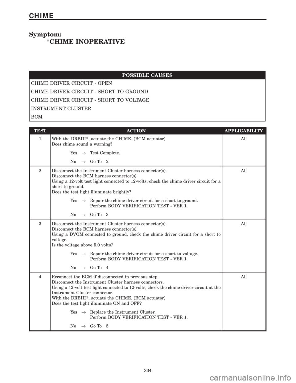
Symptom:
*CHIME INOPERATIVE
POSSIBLE CAUSES
CHIME DRIVER CIRCUIT - OPEN
CHIME DRIVER CIRCUIT - SHORT TO GROUND
CHIME DRIVER CIRCUIT - SHORT TO VOLTAGE
INSTRUMENT CLUSTER
BCM
TEST ACTION APPLICABILITY
1 With the DRBIIIt, actuate the CHIME. (BCM actuator)
Does chime sound a warning?All
Ye s®Test Complete.
No®Go To 2
2 Disconnect the Instrument Cluster harness connector(s).
Disconnect the BCM harness connector(s).
Using a 12-volt test light connected to 12-volts, check the chime driver circuit for a
short to ground.
Does the test light illuminate brightly?All
Ye s®Repair the chime driver circuit for a short to ground.
Perform BODY VERIFICATION TEST - VER 1.
No®Go To 3
3 Disconnect the Instrument Cluster harness connector(s).
Disconnect the BCM harness connector(s).
Using a DVOM connected to ground, check the chime driver circuit for a short to
voltage.
Is the voltage above 5.0 volts?All
Ye s®Repair the chime driver circuit for a short to voltage.
Perform BODY VERIFICATION TEST - VER 1.
No®Go To 4
4 Reconnect the BCM if disconnected in previous step.
Disconnect the Instrument Cluster harness connectors.
Using a 12-volt test light connected to 12-volts, check the chime driver circuit at the
Instrument Cluster connector.
With the DRBIIIt, actuate the CHIME. (BCM actuator)
Does the test light illuminate ON and OFF?All
Ye s®Replace the Instrument Cluster.
Perform BODY VERIFICATION TEST - VER 1.
No®Go To 5
334
CHIME
Page 437 of 4284

Symptom:
*NO RESPONSE FROM ORC
POSSIBLE CAUSES
CHECKING FOR VOLTAGE AT ORC
ORC GROUND CIRCUIT OPEN
PCI BUS CIRCUIT OPEN
OCCUPANT RESTRAINT CONTROLLER
TEST ACTION APPLICABILITY
1NOTE: Check the FCM for DTC's. If DTC's are present, go to the appropriate
category and perform the DTC.
Ensure that the battery is fully charged.
WARNING: TURN THE IGNITION OFF, DISCONNECT THE BATTERY AND
WAIT TWO MINUTES BEFORE PROCEEDING.
Disconnect the Occupant Restraint Controller harness connector.
Turn the ignition on and then reconnect the Battery.
Using a 12-volt test light connected to ground, probe the ORC Run Only Driver
Circuit and the ORC Run/Start Driver Circuit at the ORC connector.
NOTE: One open circuit will not cause a NO RESPONSE condition.
Is the test light illuminated on both circuits?All
Ye s®Go To 2
No®Repair the ORC Run Only Driver and ORC Run/Start Driver
circuits for an open.
Perform AIRBAG VERIFICATION TEST - VER 1.
NOTE: When reconnecting airbag system components, the ignition must be
turned off and the battery must be disconnected.
2Ensure that the battery is fully charged.
WARNING: TURN THE IGNITION OFF, DISCONNECT THE BATTERY AND
WAIT TWO MINUTES BEFORE PROCEEDING.
Disconnect the Occupant Restraint Controller harness connector.
Measure the resistance between ground and the ground circuit.
Is the resistance below 5.0 ohms?All
Ye s®Go To 3
No®Repair the Ground circuit for an open.
Perform AIRBAG VERIFICATION TEST - VER 1.
When reconnecting Airbag system components, the ignition must be turned
off and the battery must be disconnected.
408
COMMUNICATION
Page 608 of 4284

TEST ACTION APPLICABILITY
3 Turn the ignition off.
Disconnect the BCM C4 harness connector.
Disconnect the Instrument Cluster harness connector.
Turn the ignition on.
Using a 12-volt test light connected to ground, probe the Instrument Cluster Wake
Up Sense circuit.
Is the test light illuminated?All
Ye s®Repair the Instrument Cluster Wake Up Sense circuit for a short
to voltage.
Perform BODY VERIFICATION TEST - VER 1.
No®Replace the Instrument Cluster.
Perform BODY VERIFICATION TEST - VER 1.
4WARNING: WHEN THE ENGINE IS OPERATING, DO NOT STAND IN A
DIRECT LINE WITH THE FAN. DO NOT PUT YOUR HANDS NEAR THE
PULLEYS, BELTS OR FAN. DO NOT WEAR LOOSE CLOTHING.
NOTE: The conditions that set the DTC are not present at this time. The
following list may help in identifying the intermittent condition.
With the engine running at normal operating temperature, monitor the DRB
parameters related to the DTC while wiggling the wiring harness. Look for param-
eter values to change and/or a DTC to set.
Refer to any Technical Service Bulletins (TSB) that may apply.
Visually inspect the related wiring harness. Look for any chafed, pierced, pinched, or
partially broken wires.
Visually inspect the related wiring harness connectors. Look for broken, bent, pushed
out, or corroded terminals.
Were any of the above conditions present?All
Ye s®Repair as necessary
Perform BODY VERIFICATION TEST - VER 1.
No®Test Complete.
579
INSTRUMENT CLUSTER
IOD WAKEUP CLUSTER OUTPUT SHORT ÐContinued
Page 742 of 4284

TEST ACTION APPLICABILITY
4 Turn the ignition off.
Disconnect the EVIC harness connector.
Disconnect the Automatic Day/Night Mirror harness connector.
Measure the resistance of the Automatic Headlamp Switch Sensor circuit in the
EVIC harness connector to ground.
Is the resistance below 5.0 ohms?All
Ye s®Repair the Automatic Headlamp Switch Sensor circuit for a short
to ground.
Perform BODY VERIFICATION TEST - VER 1.
No®Go To 5
5 Turn the ignition off.
Disconnect the Automatic Day/Night Mirror harness connector.
Disconnect the EVIC harness connector.
Using a 12 volt test light connected to ground, probe the Automatic Headlamp Switch
Sensor circuit in the Automatic Day/Night Mirror harness connector.
Does the test illuminate brightly?All
Ye s®Repair the Automatic Headlamp Switch Sensor circuit for a
shorted to voltage.
Perform BODY VERIFICATION TEST - VER 1.
No®Go To 6
6 If there are no possible causes remaining, view repair. All
Repair
Replace the CMTC/EVIC Module.
Perform BODY VERIFICATION TEST - VER 1.
7WARNING: WHEN THE ENGINE IS OPERATING, DO NOT STAND IN A
DIRECT LINE WITH THE FAN. DO NOT PUT YOUR HANDS NEAR THE
PULLEYS, BELTS OR FAN. DO NOT WEAR LOOSE CLOTHING.
NOTE: The conditions that set the DTC are not present at this time. The
following list may help in identifying the intermittent condition.
With the engine running at normal operating temperature, monitor the DRB
parameters related to the DTC while wiggling the wiring harness. Look for param-
eter values to change and/or a DTC to set.
Refer to any Technical Service Bulletins (TSB) that may apply.
Visually inspect the related wiring harness. Look for any chafed, pierced, pinched, or
partially broken wires.
Visually inspect the related wiring harness connectors. Look for broken, bent, pushed
out, or corroded terminals.
Were any of the above conditions present?All
Ye s®Repair as necessary
Perform BODY VERIFICATION TEST - VER 1.
No®Test Complete.
713
OVERHEAD CONSOLE
EC MIRROR DAY/NIGHT LINE FAULT ÐContinued
Page 1161 of 4284
the brake pedal is applied the test will be run at 40
km/h (24 mph) regardless of brake switch state. If,
during the dynamic test, the brake pedal is applied,
the driver may feel the test through brake pedal
pulsations. This is a normal condition.
If any component exhibits a trouble condition
during system initialization or dynamic check, the
CAB will illuminate the ABS warning indicator and
TRAC OFF lamp if equipped.
3.3.6 DIAGNOSTIC MODE
To enter diagnostic mode, a vehicle speed must be
below 10 km/h (6 mph) and no ABS condition
present. If vehicle speed is not below 10 km/h
(6 mph), a ªNo Responseº message could be dis-
played by the DRBIIIt. The following are charac-
teristics of diagnostic mode:
± The amber ABS warning indicator will blink
rapidly (about 1/2 second ON and 1/2 second
OFF). If a hard trouble code, such as Valve
Power Feed Failure code is present, the indi-
cator will be illuminated without blinking un-
til the trouble condition is cleared.
± Antilock operation is disabled.
± The HCU valves cannot be actuated when the
vehicle speed is above 8 km/h (5 mph). If valve
actuation is attempted above 8 km/h (5 mph), a
ªNo Responseº message will be displayed on
the DRBIIIt.
3.4 DIAGNOSTIC TROUBLE CODES
The controller antilock brake may report any of
the following diagnostic trouble codes:
CLUSTER LAMP FAILURE
VALVE POWER FEED FAILURE
BUS SYSTEM COMMUNICATION FAILURE
CAB INTERNAL FAILURE
LEFT FRONT SENSOR CIRCUIT FAILURE
LEFT FRONT WHEEL SPEED SIGNAL
FAILURE
LEFT REAR SENSOR CIRCUIT FAILURE
LEFT REAR WHEEL SPEED SIGNAL
FAILURE
PUMP CIRCUIT FAILURE
RIGHT FRONT SENSOR CIRCUIT FAILURE
RIGHT FRONT WHEEL SPEED SIGNAL
FAILURE
RIGHT REAR SENSOR CIRCUIT FAILURE
RIGHT REAR WHEEL SPEED SIGNAL
FAILURE
SYSTEM OVERVOLTAGE
SYSTEM UNDERVOLTAGE
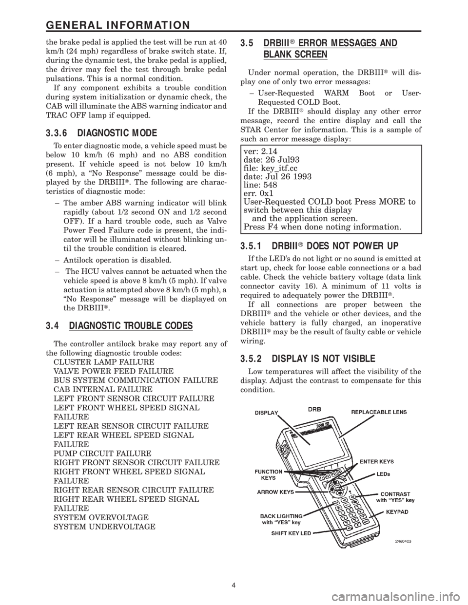
3.5 DRBIIITERROR MESSAGES AND
BLANK SCREEN
Under normal operation, the DRBIIItwill dis-
play one of only two error messages:
± User-Requested WARM Boot or User-
Requested COLD Boot.
If the DRBIIItshould display any other error
message, record the entire display and call the
STAR Center for information. This is a sample of
such an error message display:
ver: 2.14
date: 26 Jul93
file: key_itf.cc
date: Jul 26 1993
line: 548
err. 0x1
User-Requested COLD boot Press MORE to
switch between this display
and the application screen.
Press F4 when done noting information.
3.5.1 DRBIIITDOES NOT POWER UP
If the LED's do not light or no sound is emitted at
start up, check for loose cable connections or a bad
cable. Check the vehicle battery voltage (data link
connector cavity 16). A minimum of 11 volts is
required to adequately power the DRBIIIt.
If all connections are proper between the
DRBIIItand the vehicle or other devices, and the
vehicle battery is fully charged, an inoperative
DRBIIItmay be the result of faulty cable or vehicle
wiring.
3.5.2 DISPLAY IS NOT VISIBLE
Low temperatures will affect the visibility of the
display. Adjust the contrast to compensate for this
condition.
4
GENERAL INFORMATION
Page 1163 of 4284
4.3 WARNINGS
4.3.1 VEHICLE DAMAGE WARNINGS
Before disconnecting any control module, make
sure the ignition is ``off ''. Failure to do so could
damage the module.
When testing voltage or continuity at any control
module, use the terminal side (not the wire end) of
the connector. Do not probe a wire through the
insulation, this will damage it and eventually cause
it to fail because of corrosion.
Be careful when performing electrical tests so as
to prevent accidental shorting of terminals. Such
mistakes can damage fuses or components. Also, a
second code could be set, making diagnosis of the
original problem more difficult.
4.3.2 ROAD TESTING A COMPLAINT
VEHICLE
Some complaints will require a test drive as part
of the repair verification procedure. The purpose of
the test drive is to try to duplicate the diagnostic
code or symptom condition.
WARNING: BEFORE ROAD TESTING A
VEHICLE, BE SURE THAT ALL
COMPONENTS ARE REASSEMBLED.
DURING THE TEST DRIVE, DO NOT TRY TO
READ THE DRB SCREEN WHILE IN MOTION.
DO NOT HANG THE DRBIIITFROM THE
REAR VIEW MIRROR OR OPERATE IT
YOURSELF. HAVE AN ASSISTANT
AVAILABLE TO OPERATE THE DRBIIIT.
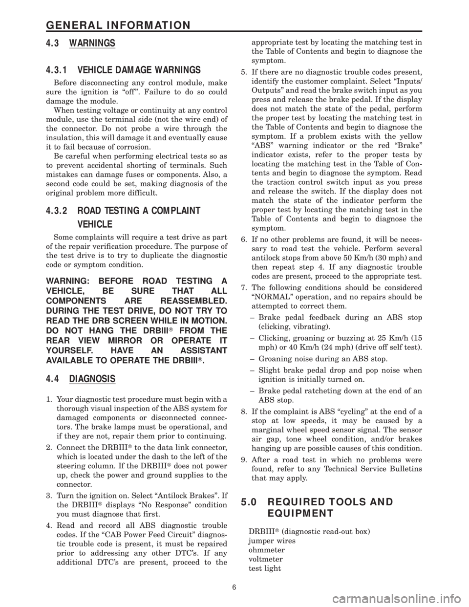
4.4 DIAGNOSIS
1. Your diagnostic test procedure must begin with a
thorough visual inspection of the ABS system for
damaged components or disconnected connec-
tors. The brake lamps must be operational, and
if they are not, repair them prior to continuing.
2. Connect the DRBIIItto the data link connector,
which is located under the dash to the left of the
steering column. If the DRBIIItdoes not power
up, check the power and ground supplies to the
connector.
3. Turn the ignition on. Select ªAntilock Brakesº. If
the DRBIIItdisplays ªNo Responseº condition
you must diagnose that first.
4. Read and record all ABS diagnostic trouble
codes. If the ªCAB Power Feed Circuitº diagnos-
tic trouble code is present, it must be repaired
prior to addressing any other DTC's. If any
additional DTC's are present, proceed to theappropriate test by locating the matching test in
the Table of Contents and begin to diagnose the
symptom.
5. If there are no diagnostic trouble codes present,
identify the customer complaint. Select ªInputs/
Outputsº and read the brake switch input as you
press and release the brake pedal. If the display
does not match the state of the pedal, perform
the proper test by locating the matching test in
the Table of Contents and begin to diagnose the
symptom. If a problem exists with the yellow
ªABSº warning indicator or the red ªBrakeº
indicator exists, refer to the proper tests by
locating the matching test in the Table of Con-
tents and begin to diagnose the symptom. Read
the traction control switch input as you press
and release the switch. If the display does not
match the state of the indicator perform the
proper test by locating the matching test in the
Table of Contents and begin to diagnose the
symptom.
6. If no other problems are found, it will be neces-
sary to road test the vehicle. Perform several
antilock stops from above 50 Km/h (30 mph) and
then repeat step 4. If any diagnostic trouble
codes are present, proceed to the appropriate test.
7. The following conditions should be considered
ªNORMALº operation, and no repairs should be
attempted to correct them.
± Brake pedal feedback during an ABS stop
(clicking, vibrating).
± Clicking, groaning or buzzing at 25 Km/h (15
mph) or 40 Km/h (24 mph) (drive off self test).
± Groaning noise during an ABS stop.
± Slight brake pedal drop and pop noise when
ignition is initially turned on.
± Brake pedal ratcheting down at the end of an
ABS stop.
8. If the complaint is ABS ªcyclingº at the end of a
stop at low speeds, it may be caused by a
marginal wheel speed sensor signal. The sensor
air gap, tone wheel condition, and/or brakes
hanging up are possible causes of this condition.
9. After a road test in which no problems were
found, refer to any Technical Service Bulletins
that may apply.
5.0 REQUIRED TOOLS AND
EQUIPMENT
DRBIIIt(diagnostic read-out box)
jumper wires
ohmmeter
voltmeter
test light
6
GENERAL INFORMATION
Page 1304 of 4284
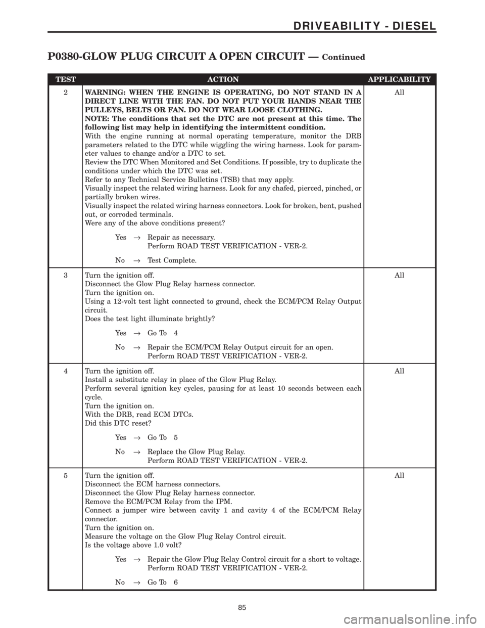
TEST ACTION APPLICABILITY
2WARNING: WHEN THE ENGINE IS OPERATING, DO NOT STAND IN A
DIRECT LINE WITH THE FAN. DO NOT PUT YOUR HANDS NEAR THE
PULLEYS, BELTS OR FAN. DO NOT WEAR LOOSE CLOTHING.
NOTE: The conditions that set the DTC are not present at this time. The
following list may help in identifying the intermittent condition.
With the engine running at normal operating temperature, monitor the DRB
parameters related to the DTC while wiggling the wiring harness. Look for param-
eter values to change and/or a DTC to set.
Review the DTC When Monitored and Set Conditions. If possible, try to duplicate the
conditions under which the DTC was set.
Refer to any Technical Service Bulletins (TSB) that may apply.
Visually inspect the related wiring harness. Look for any chafed, pierced, pinched, or
partially broken wires.
Visually inspect the related wiring harness connectors. Look for broken, bent, pushed
out, or corroded terminals.
Were any of the above conditions present?All
Ye s®Repair as necessary.
Perform ROAD TEST VERIFICATION - VER-2.
No®Test Complete.
3 Turn the ignition off.
Disconnect the Glow Plug Relay harness connector.
Turn the ignition on.
Using a 12-volt test light connected to ground, check the ECM/PCM Relay Output
circuit.
Does the test light illuminate brightly?All
Ye s®Go To 4
No®Repair the ECM/PCM Relay Output circuit for an open.
Perform ROAD TEST VERIFICATION - VER-2.
4 Turn the ignition off.
Install a substitute relay in place of the Glow Plug Relay.
Perform several ignition key cycles, pausing for at least 10 seconds between each
cycle.
Turn the ignition on.
With the DRB, read ECM DTCs.
Did this DTC reset?All
Ye s®Go To 5
No®Replace the Glow Plug Relay.
Perform ROAD TEST VERIFICATION - VER-2.
5 Turn the ignition off.
Disconnect the ECM harness connectors.
Disconnect the Glow Plug Relay harness connector.
Remove the ECM/PCM Relay from the IPM.
Connect a jumper wire between cavity 1 and cavity 4 of the ECM/PCM Relay
connector.
Turn the ignition on.
Measure the voltage on the Glow Plug Relay Control circuit.
Is the voltage above 1.0 volt?All
Ye s®Repair the Glow Plug Relay Control circuit for a short to voltage.
Perform ROAD TEST VERIFICATION - VER-2.
No®Go To 6
85
DRIVEABILITY - DIESEL
P0380-GLOW PLUG CIRCUIT A OPEN CIRCUIT ÐContinued
Page 1337 of 4284
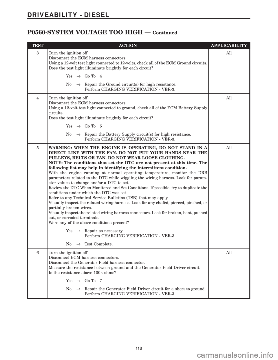
TEST ACTION APPLICABILITY
3 Turn the ignition off.
Disconnect the ECM harness connectors.
Using a 12-volt test light connected to 12-volts, check all of the ECM Ground circuits.
Does the test light illuminate brightly for each circuit?All
Ye s®Go To 4
No®Repair the Ground circuit(s) for high resistance.
Perform CHARGING VERIFICATION - VER-3.
4 Turn the ignition off.
Disconnect the ECM harness connectors.
Using a 12-volt test light connected to ground, check all of the ECM Battery Supply
circuits.
Does the test light illuminate brightly for each circuit?All
Ye s®Go To 5
No®Repair the Battery Supply circuit(s) for high resistance.
Perform CHARGING VERIFICATION - VER-3.
5WARNING: WHEN THE ENGINE IS OPERATING, DO NOT STAND IN A
DIRECT LINE WITH THE FAN. DO NOT PUT YOUR HANDS NEAR THE
PULLEYS, BELTS OR FAN. DO NOT WEAR LOOSE CLOTHING.
NOTE: The conditions that set the DTC are not present at this time. The
following list may help in identifying the intermittent condition.
With the engine running at normal operating temperature, monitor the DRB
parameters related to the DTC while wiggling the wiring harness. Look for param-
eter values to change and/or a DTC to set.
Review the DTC When Monitored and Set Conditions. If possible, try to duplicate the
conditions under which the DTC was set.
Refer to any Technical Service Bulletins (TSB) that may apply.
Visually inspect the related wiring harness. Look for any chafed, pierced, pinched, or
partially broken wires.
Visually inspect the related wiring harness connectors. Look for broken, bent, pushed
out, or corroded terminals.
Were any of the above conditions present?All
Ye s®Repair as necessary
Perform CHARGING VERIFICATION - VER-3.
No®Test Complete.
6 Turn the ignition off.
Disconnect ECM harness connectors.
Disconnect the Generator Field harness connector.
Measure the resistance between ground and the Generator Field Driver circuit.
Is the resistance above 100k ohms?All
Ye s®Go To 7
No®Repair the Generator Field Driver circuit for a short to ground.
Perform CHARGING VERIFICATION - VER-3.
11 8
DRIVEABILITY - DIESEL
P0560-SYSTEM VOLTAGE TOO HIGH ÐContinued