2001 CHRYSLER VOYAGER warning light
[x] Cancel search: warning lightPage 1348 of 4284
Symptom:
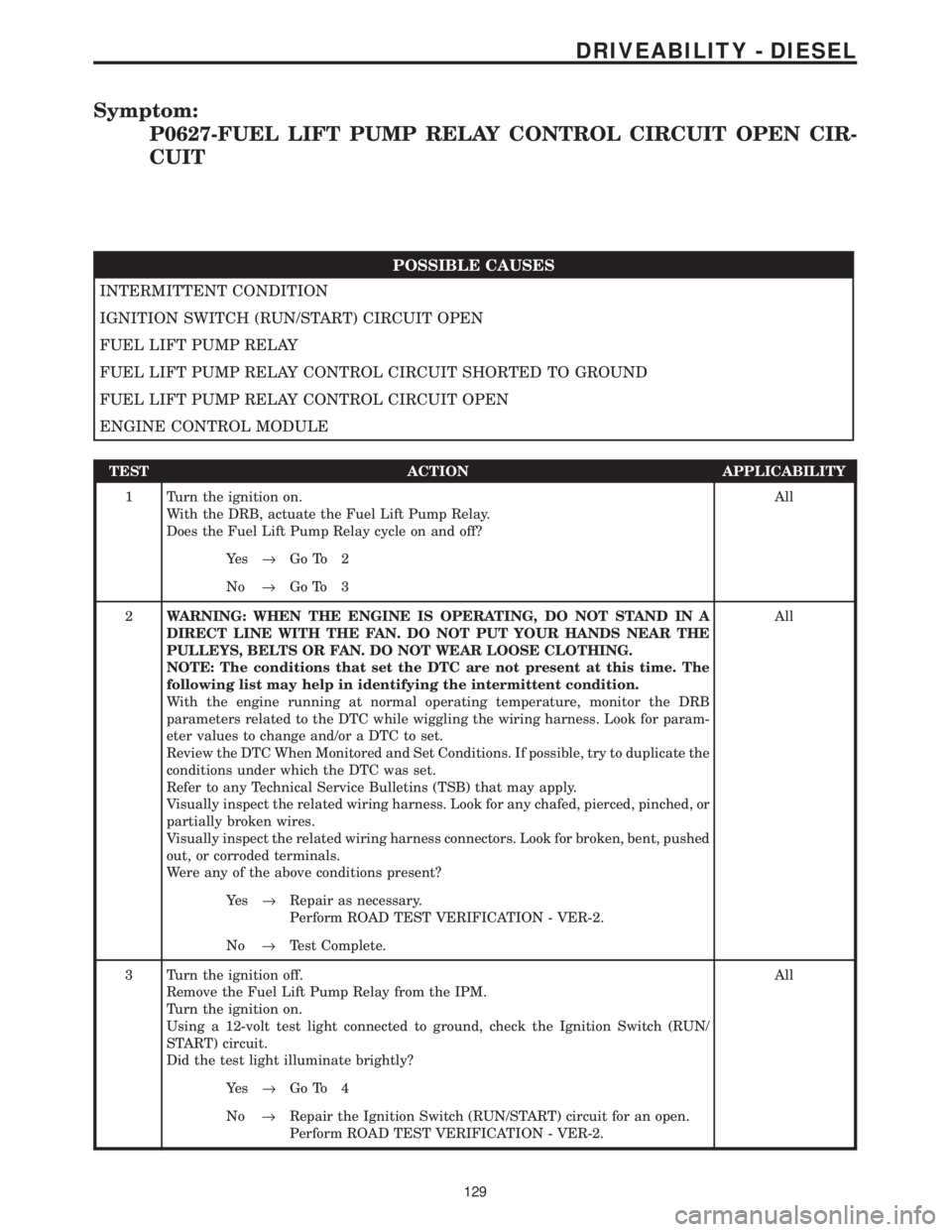
P0627-FUEL LIFT PUMP RELAY CONTROL CIRCUIT OPEN CIR-
CUIT
POSSIBLE CAUSES
INTERMITTENT CONDITION
IGNITION SWITCH (RUN/START) CIRCUIT OPEN
FUEL LIFT PUMP RELAY
FUEL LIFT PUMP RELAY CONTROL CIRCUIT SHORTED TO GROUND
FUEL LIFT PUMP RELAY CONTROL CIRCUIT OPEN
ENGINE CONTROL MODULE
TEST ACTION APPLICABILITY
1 Turn the ignition on.
With the DRB, actuate the Fuel Lift Pump Relay.
Does the Fuel Lift Pump Relay cycle on and off?All
Ye s®Go To 2
No®Go To 3
2WARNING: WHEN THE ENGINE IS OPERATING, DO NOT STAND IN A
DIRECT LINE WITH THE FAN. DO NOT PUT YOUR HANDS NEAR THE
PULLEYS, BELTS OR FAN. DO NOT WEAR LOOSE CLOTHING.
NOTE: The conditions that set the DTC are not present at this time. The
following list may help in identifying the intermittent condition.
With the engine running at normal operating temperature, monitor the DRB
parameters related to the DTC while wiggling the wiring harness. Look for param-
eter values to change and/or a DTC to set.
Review the DTC When Monitored and Set Conditions. If possible, try to duplicate the
conditions under which the DTC was set.
Refer to any Technical Service Bulletins (TSB) that may apply.
Visually inspect the related wiring harness. Look for any chafed, pierced, pinched, or
partially broken wires.
Visually inspect the related wiring harness connectors. Look for broken, bent, pushed
out, or corroded terminals.
Were any of the above conditions present?All
Ye s®Repair as necessary.
Perform ROAD TEST VERIFICATION - VER-2.
No®Test Complete.
3 Turn the ignition off.
Remove the Fuel Lift Pump Relay from the IPM.
Turn the ignition on.
Using a 12-volt test light connected to ground, check the Ignition Switch (RUN/
START) circuit.
Did the test light illuminate brightly?All
Ye s®Go To 4
No®Repair the Ignition Switch (RUN/START) circuit for an open.
Perform ROAD TEST VERIFICATION - VER-2.
129
DRIVEABILITY - DIESEL
Page 1359 of 4284
TEST ACTION APPLICABILITY
3WARNING: KEEP CLEAR OF THE ENGINE'S MOVING PARTS.
NOTE: The conditions that set the DTC are not present at this time. The
following list may help in identifying the intermittent condition.
With the engine running at normal operating temperature, monitor the DRB
parameters related to the DTC while wiggling the wiring harness. Look for param-
eter values to change and/or a DTC to set.
Review the DRB Freeze Frame information. If possible, try to duplicate the
conditions under which the DTC was set.
Refer to any Technical Service Bulletins (TSB) that may apply.
Visually inspect the related wiring harness. Look for any chafed, pierced, pinched, or
partially broken wires.
Visually inspect the related wiring harness connectors. Look for broken, bent, pushed
out, or corroded terminals.
Were any of the above conditions present?All
Ye s®Repair as necessary.
Perform ROAD TEST VERIFICATION - VER-2.
No®Test Complete.
4 Turn the ignition off.
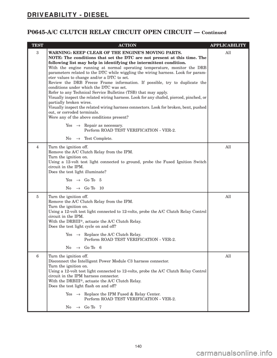
Remove the A/C Clutch Relay from the IPM.
Turn the ignition on.
Using a 12-volt test light connected to ground, probe the Fused Ignition Switch
circuit in the IPM.
Does the test light illuminate?All
Ye s®Go To 5
No®Go To 10
5 Turn the ignition off.
Remove the A/C Clutch Relay from the IPM.
Turn the ignition on.
Using a 12-volt test light connected to 12-volts, probe the A/C Clutch Relay Control
circuit in the IPM.
With the DRBIIIt, actuate the A/C Clutch Relay.
Does the test light cycle on and off?All
Ye s®Replace the A/C Clutch Relay.
Perform ROAD TEST VERIFICATION - VER-2.
No®Go To 6
6 Turn the ignition off.
Disconnect the Intelligent Power Module C3 harness connector.
Turn the ignition on.
Using a 12-volt test light connected to 12-volts, probe the A/C Clutch Relay Control
circuit in the IPM harness connector.
With the DRBIIIt, actuate the A/C Clutch Relay.
Does the test light flash on and off?All
Ye s®Replace the IPM Fused & Relay Center.
Perform ROAD TEST VERIFICATION - VER-2.
No®Go To 7
140
DRIVEABILITY - DIESEL
P0645-A/C CLUTCH RELAY CIRCUIT OPEN CIRCUIT ÐContinued
Page 1362 of 4284
TEST ACTION APPLICABILITY
3WARNING: KEEP CLEAR OF THE ENGINE'S MOVING PARTS.
NOTE: The conditions that set the DTC are not present at this time. The
following list may help in identifying the intermittent condition.
With the engine running at normal operating temperature, monitor the DRB
parameters related to the DTC while wiggling the wiring harness. Look for param-
eter values to change and/or a DTC to set.
Review the DRB Freeze Frame information. If possible, try to duplicate the
conditions under which the DTC was set.
Refer to any Technical Service Bulletins (TSB) that may apply.
Visually inspect the related wiring harness. Look for any chafed, pierced, pinched, or
partially broken wires.
Visually inspect the related wiring harness connectors. Look for broken, bent, pushed
out, or corroded terminals.
Were any of the above conditions present?All
Ye s®Repair as necessary.
Perform ROAD TEST VERIFICATION - VER-2.
No®Test Complete.
4 Turn the ignition off.
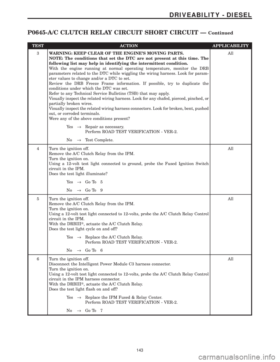
Remove the A/C Clutch Relay from the IPM.
Turn the ignition on.
Using a 12-volt test light connected to ground, probe the Fused Ignition Switch
circuit in the IPM.
Does the test light illuminate?All
Ye s®Go To 5
No®Go To 9
5 Turn the ignition off.
Remove the A/C Clutch Relay from the IPM.
Turn the ignition on.
Using a 12-volt test light connected to 12-volts, probe the A/C Clutch Relay Control
circuit in the IPM.
With the DRBIIIt, actuate the A/C Clutch Relay.
Does the test light cycle on and off?All
Ye s®Replace the A/C Clutch Relay.
Perform ROAD TEST VERIFICATION - VER-2.
No®Go To 6
6 Turn the ignition off.
Disconnect the Intelligent Power Module C3 harness connector.
Turn the ignition on.
Using a 12-volt test light connected to 12-volts, probe the A/C Clutch Relay Control
circuit in the IPM harness connector.
With the DRBIIIt, actuate the A/C Clutch Relay.
Does the test light flash on and off?All
Ye s®Replace the IPM Fused & Relay Center.
Perform ROAD TEST VERIFICATION - VER-2.
No®Go To 7
143
DRIVEABILITY - DIESEL
P0645-A/C CLUTCH RELAY CIRCUIT SHORT CIRCUIT ÐContinued
Page 1378 of 4284
TEST ACTION APPLICABILITY
1WARNING: THE FUEL INJECTION PUMP SUPPLIES HIGH PRESSURE
FUEL TO EACH INDIVIDUAL INJECTOR THROUGH HIGH-PRESSURE
FUEL LINES. FUEL UNDER HIGH PRESSURE CAN PENETRATE SKIN
AND CAUSE PERSONAL INJURY. WEAR SAFETY GOGGLES AND ADE-
QUATE PROTECTIVE CLOTHING.
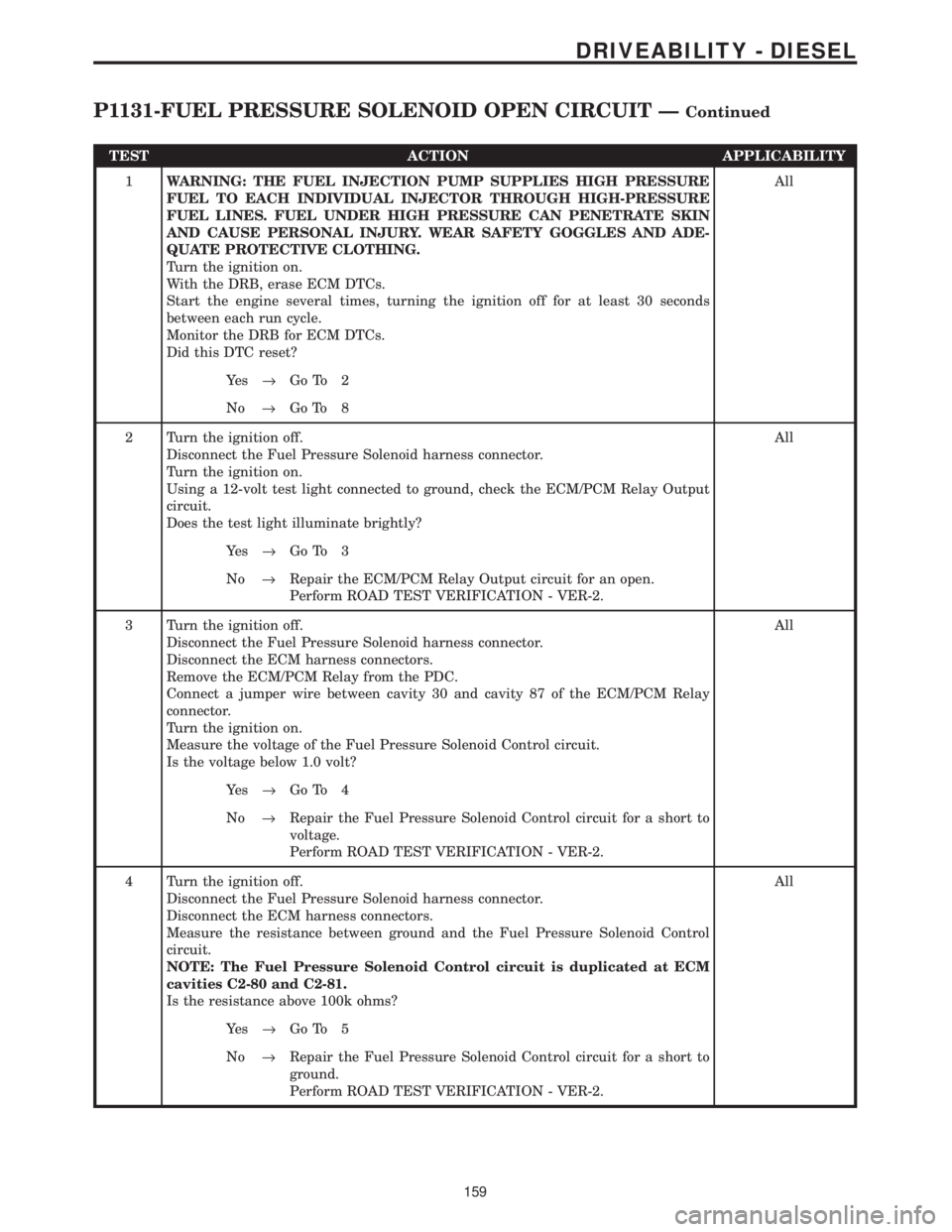
Turn the ignition on.
With the DRB, erase ECM DTCs.
Start the engine several times, turning the ignition off for at least 30 seconds
between each run cycle.
Monitor the DRB for ECM DTCs.
Did this DTC reset?All
Ye s®Go To 2
No®Go To 8
2 Turn the ignition off.
Disconnect the Fuel Pressure Solenoid harness connector.
Turn the ignition on.
Using a 12-volt test light connected to ground, check the ECM/PCM Relay Output
circuit.
Does the test light illuminate brightly?All
Ye s®Go To 3
No®Repair the ECM/PCM Relay Output circuit for an open.
Perform ROAD TEST VERIFICATION - VER-2.
3 Turn the ignition off.
Disconnect the Fuel Pressure Solenoid harness connector.
Disconnect the ECM harness connectors.
Remove the ECM/PCM Relay from the PDC.
Connect a jumper wire between cavity 30 and cavity 87 of the ECM/PCM Relay
connector.
Turn the ignition on.
Measure the voltage of the Fuel Pressure Solenoid Control circuit.
Is the voltage below 1.0 volt?All
Ye s®Go To 4
No®Repair the Fuel Pressure Solenoid Control circuit for a short to
voltage.
Perform ROAD TEST VERIFICATION - VER-2.
4 Turn the ignition off.
Disconnect the Fuel Pressure Solenoid harness connector.
Disconnect the ECM harness connectors.
Measure the resistance between ground and the Fuel Pressure Solenoid Control
circuit.
NOTE: The Fuel Pressure Solenoid Control circuit is duplicated at ECM
cavities C2-80 and C2-81.
Is the resistance above 100k ohms?All
Ye s®Go To 5
No®Repair the Fuel Pressure Solenoid Control circuit for a short to
ground.
Perform ROAD TEST VERIFICATION - VER-2.
159
DRIVEABILITY - DIESEL
P1131-FUEL PRESSURE SOLENOID OPEN CIRCUIT ÐContinued
Page 1384 of 4284
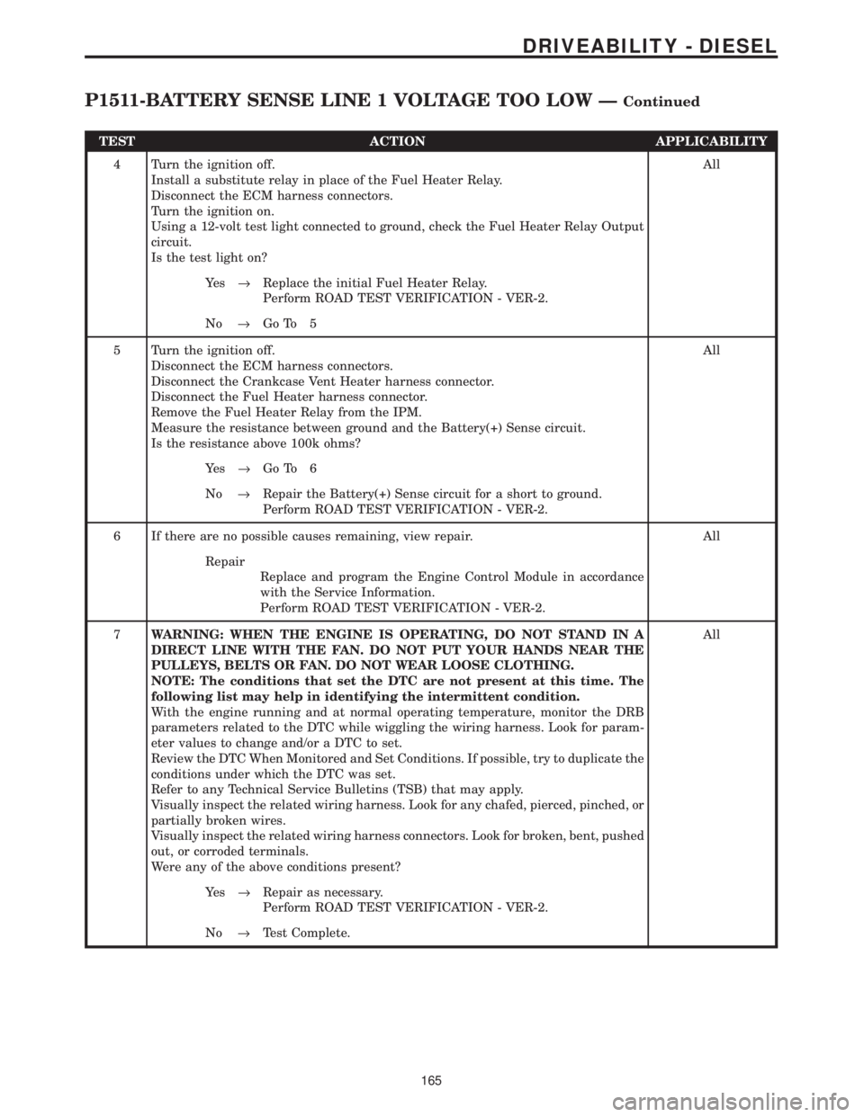
TEST ACTION APPLICABILITY
4 Turn the ignition off.
Install a substitute relay in place of the Fuel Heater Relay.
Disconnect the ECM harness connectors.
Turn the ignition on.
Using a 12-volt test light connected to ground, check the Fuel Heater Relay Output
circuit.
Is the test light on?All
Ye s®Replace the initial Fuel Heater Relay.
Perform ROAD TEST VERIFICATION - VER-2.
No®Go To 5
5 Turn the ignition off.
Disconnect the ECM harness connectors.
Disconnect the Crankcase Vent Heater harness connector.
Disconnect the Fuel Heater harness connector.
Remove the Fuel Heater Relay from the IPM.
Measure the resistance between ground and the Battery(+) Sense circuit.
Is the resistance above 100k ohms?All
Ye s®Go To 6
No®Repair the Battery(+) Sense circuit for a short to ground.
Perform ROAD TEST VERIFICATION - VER-2.
6 If there are no possible causes remaining, view repair. All
Repair
Replace and program the Engine Control Module in accordance
with the Service Information.
Perform ROAD TEST VERIFICATION - VER-2.
7WARNING: WHEN THE ENGINE IS OPERATING, DO NOT STAND IN A
DIRECT LINE WITH THE FAN. DO NOT PUT YOUR HANDS NEAR THE
PULLEYS, BELTS OR FAN. DO NOT WEAR LOOSE CLOTHING.
NOTE: The conditions that set the DTC are not present at this time. The
following list may help in identifying the intermittent condition.
With the engine running and at normal operating temperature, monitor the DRB
parameters related to the DTC while wiggling the wiring harness. Look for param-
eter values to change and/or a DTC to set.
Review the DTC When Monitored and Set Conditions. If possible, try to duplicate the
conditions under which the DTC was set.
Refer to any Technical Service Bulletins (TSB) that may apply.
Visually inspect the related wiring harness. Look for any chafed, pierced, pinched, or
partially broken wires.
Visually inspect the related wiring harness connectors. Look for broken, bent, pushed
out, or corroded terminals.
Were any of the above conditions present?All
Ye s®Repair as necessary.
Perform ROAD TEST VERIFICATION - VER-2.
No®Test Complete.
165
DRIVEABILITY - DIESEL
P1511-BATTERY SENSE LINE 1 VOLTAGE TOO LOW ÐContinued
Page 1430 of 4284
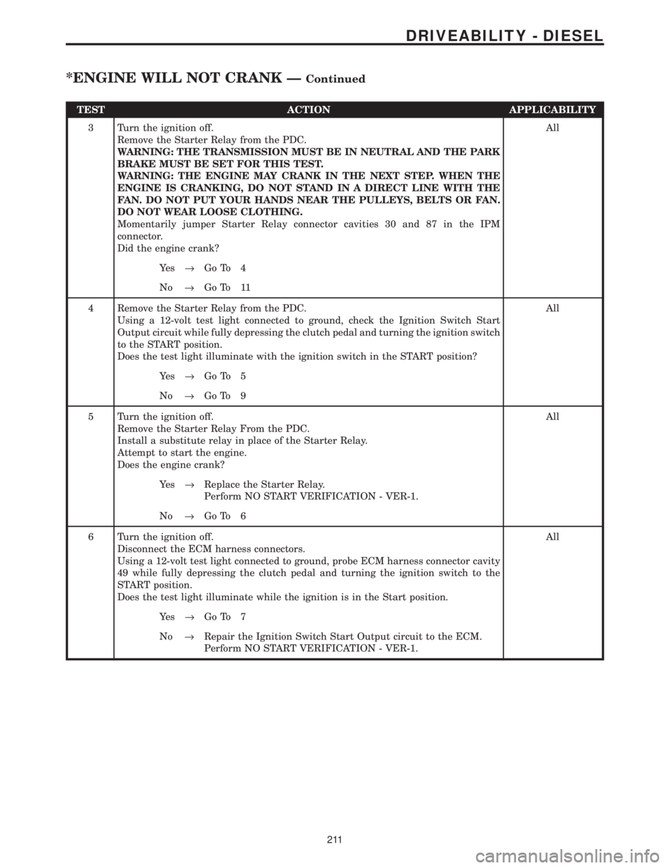
TEST ACTION APPLICABILITY
3 Turn the ignition off.
Remove the Starter Relay from the PDC.
WARNING: THE TRANSMISSION MUST BE IN NEUTRAL AND THE PARK
BRAKE MUST BE SET FOR THIS TEST.
WARNING: THE ENGINE MAY CRANK IN THE NEXT STEP. WHEN THE
ENGINE IS CRANKING, DO NOT STAND IN A DIRECT LINE WITH THE
FAN. DO NOT PUT YOUR HANDS NEAR THE PULLEYS, BELTS OR FAN.
DO NOT WEAR LOOSE CLOTHING.
Momentarily jumper Starter Relay connector cavities 30 and 87 in the IPM
connector.
Did the engine crank?All
Ye s®Go To 4
No®Go To 11
4 Remove the Starter Relay from the PDC.
Using a 12-volt test light connected to ground, check the Ignition Switch Start
Output circuit while fully depressing the clutch pedal and turning the ignition switch
to the START position.
Does the test light illuminate with the ignition switch in the START position?All
Ye s®Go To 5
No®Go To 9
5 Turn the ignition off.
Remove the Starter Relay From the PDC.
Install a substitute relay in place of the Starter Relay.
Attempt to start the engine.
Does the engine crank?All
Ye s®Replace the Starter Relay.
Perform NO START VERIFICATION - VER-1.
No®Go To 6
6 Turn the ignition off.
Disconnect the ECM harness connectors.
Using a 12-volt test light connected to ground, probe ECM harness connector cavity
49 while fully depressing the clutch pedal and turning the ignition switch to the
START position.
Does the test light illuminate while the ignition is in the Start position.All
Ye s®Go To 7
No®Repair the Ignition Switch Start Output circuit to the ECM.
Perform NO START VERIFICATION - VER-1.
211
DRIVEABILITY - DIESEL
*ENGINE WILL NOT CRANK ÐContinued
Page 1473 of 4284
FASTENER IDENTIFICATION
DESCRIPTION
The SAE bolt strength grades range from grade 2
to grade 8. The higher the grade number, the greater
the bolt strength. Identification is determined by the
line marks on the top of each bolt head. The actual
bolt strength grade corresponds to the number of line
marks plus 2. The most commonly used metric bolt
strength classes are 9.8 and 10.9. The metric
strength class identification number is imprinted on
the head of the bolt. The higher the class number,
the greater the bolt strength. Some metric nuts are
imprinted with a single-digit strength class on the
nut face. Refer to the Fastener Identification and
Fastener Strength Charts.
FASTENER USAGE
DESCRIPTION - FASTENER USAGE
WARNING: USE OF AN INCORRECT FASTENER
MAY RESULT IN COMPONENT DAMAGE OR PER-
SONAL INJURY.
Figure art, specifications and torque references in
this Service Manual are identified in metric and SAE
format.
During any maintenance or repair procedures, it is
important to salvage all fasteners (nuts, bolts, etc.)
for reassembly. If the fastener is not salvageable, a
fastener of equivalent specification must be used.
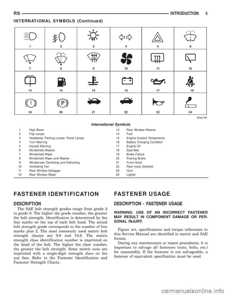
International Symbols
1 High Beam 13 Rear Window Washer
2 Fog Lamps 14 Fuel
3 Headlamp, Parking Lamps, Panel Lamps 15 Engine Coolant Temperature
4 Turn Warning 16 Battery Charging Condition
5 Hazard Warning 17 Engine Oil
6 Windshield Washer 18 Seat Belt
7 Windshield Wiper 19 Brake Failure
8 Windshield Wiper and Washer 20 Parking Brake
9 Windscreen Demisting and Defrosting 21 Front Hood
10 Ventilating Fan 22 Rear hood (Decklid)
11 Rear Window Defogger 23 Horn
12 Rear Window Wiper 24 Lighter
RSINTRODUCTION5
INTERNATIONAL SYMBOLS (Continued)
Page 1483 of 4284
FASTENER USAGE
DESCRIPTION
WARNING: USE OF AN INCORRECT FASTENER
MAY RESULT IN COMPONENT DAMAGE OR PER-
SONAL INJURY.
Figure art, specifications and torque references in
this Service Manual are identified in metric and SAE
format.
During any maintenance or repair procedures, it is
important to salvage all fasteners (nuts, bolts, etc.)
for reassembly. If the fastener is not salvageable, a
fastener of equivalent specification must be used.
THREADED HOLE REPAIR
DESCRIPTION
Most stripped threaded holes can be repaired using
a Helicoilt. Follow the vehicle or Helicoiltrecommen-
dations for application and repair procedures.
INTERNATIONAL VEHICLE
CONTROL & DISPLAY
SYMBOLS
DESCRIPTION
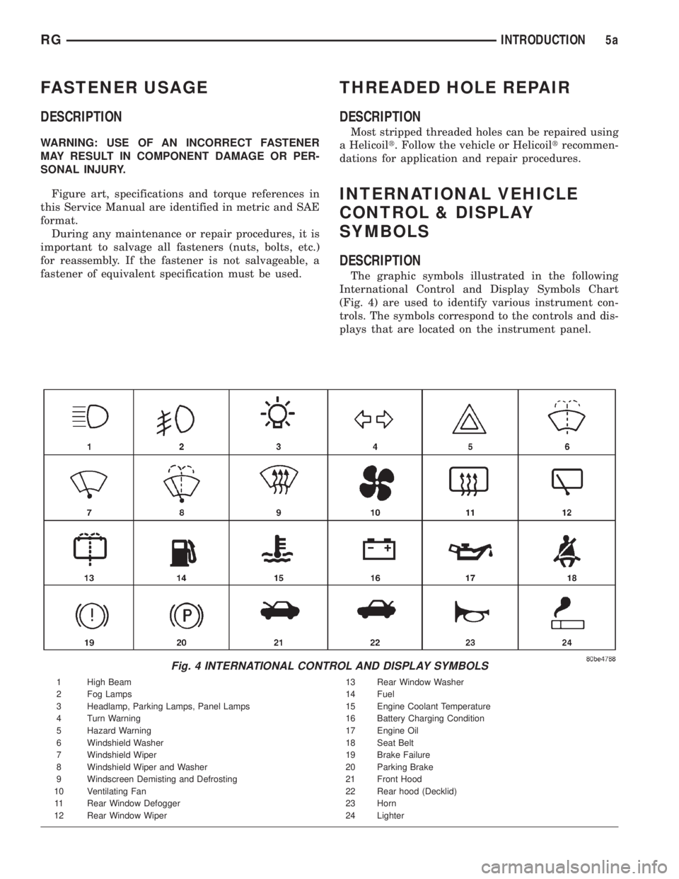
The graphic symbols illustrated in the following
International Control and Display Symbols Chart
(Fig. 4) are used to identify various instrument con-
trols. The symbols correspond to the controls and dis-
plays that are located on the instrument panel.
Fig. 4 INTERNATIONAL CONTROL AND DISPLAY SYMBOLS
1 High Beam 13 Rear Window Washer
2 Fog Lamps 14 Fuel
3 Headlamp, Parking Lamps, Panel Lamps 15 Engine Coolant Temperature
4 Turn Warning 16 Battery Charging Condition
5 Hazard Warning 17 Engine Oil
6 Windshield Washer 18 Seat Belt
7 Windshield Wiper 19 Brake Failure
8 Windshield Wiper and Washer 20 Parking Brake
9 Windscreen Demisting and Defrosting 21 Front Hood
10 Ventilating Fan 22 Rear hood (Decklid)
11 Rear Window Defogger 23 Horn
12 Rear Window Wiper 24 Lighter
RGINTRODUCTION5a