2001 CHRYSLER VOYAGER CPA not
[x] Cancel search: CPA notPage 17 of 4284

TABLE OF CONTENTS - Continued
FUEL GAUGE CHECKSUM FAILURE......................................571
FUEL LEVEL SENDING UNIT INPUT OPEN................................572
FUEL LEVEL SENDING UNIT INPUT SHORT...............................574
IOD WAKEUP CLUSTER OUTPUT OPEN..................................576
IOD WAKEUP CLUSTER OUTPUT SHORT.................................578
LEFT TURN SIGNAL INDICATOR OPEN (HIGHLINE).........................580
LEFT TURN SIGNAL INDICATOR OPEN (LOWLINE).........................582
LEFT TURN SIGNAL INDICATOR SHORT (HIGHLINE)........................584
LEFT TURN SIGNAL INDICATOR SHORT (LOWLINE)........................586
LOOPBACK FAILURE...................................................588
NO ABS BUS MESSAGES RECEIVED.....................................589
NO BCM BUS MESSAGES RECEIVED....................................590
NO FCM BUS MESSAGES RECEIVED....................................591
NO ORC BUS MESSAGES RECEIVED....................................592
NO PCM BUS MESSAGES RECEIVED....................................593
NO TCM BUS MESSAGES RECEIVED....................................594
PANEL DIMMING OUTPUT SHORT.......................................595
REAR FOG INDICATOR OUTPUT OPEN...................................600
REAR FOG INDICATOR OUTPUT SHORT..................................602
RIGHT TURN SIGNAL INDICATOR OPEN (HIGHLINE)........................604
RIGHT TURN SIGNAL INDICATOR OPEN (LOWLINE)........................606
RIGHT TURN SIGNAL INDICATOR SHORT (HIGHLINE)......................608
RIGHT TURN SIGNAL INDICATOR SHORT (LOWLINE).......................610
SPEEDOMETER CHECKSUM FAILURE....................................612
TACHOMETER CHECKSUM FAILURE.....................................613
TCM MESSAGE MISMATCH.............................................614
TEMPERATURE GAUGE CHECKSUM FAILURE.............................615
*ANY PCI BUS INDICATOR INOPERATIVE.................................616
INTELLIGENT POWER MODULE
ACCESSORY POWER OUTPUT #1 OPEN.................................617
ACCESSORY POWER OUTPUT #1 SHORTED TO BATTERY..................619
ACCESSORY POWER OUTPUT #2 OPEN.................................621
ACCESSORY POWER OUTPUT #2 SHORTED TO BATTERY..................623
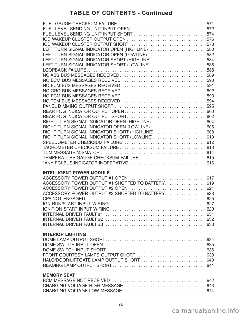
CPA NOT ENGAGED...................................................625
IGN RUN/START INPUT WIRING.........................................627
IGNITION START INPUT WIRING.........................................629
INTERNAL DRIVER FAULT #1............................................631
INTERNAL DRIVER FAULT #2............................................632
INTERNAL DRIVER FAULT #3............................................633
INTERIOR LIGHTING
DOME LAMP OUTPUT SHORT...........................................634
DOME SWITCH INPUT OPEN............................................635
DOME SWITCH INPUT SHORT...........................................636
FRONT COURTESY LAMPS OUTPUT SHORT..............................638
HALO/DOOR/LIFTGATE LAMP OUTPUT SHORT............................640
READING LAMP OUTPUT SHORT........................................641
MEMORY SEAT
BCM MESSAGE NOT RECEIVED.........................................642
CHARGING VOLTAGE HIGH MESSAGE...................................643
CHARGING VOLTAGE LOW MESSAGE....................................644
xiv
Page 45 of 4284

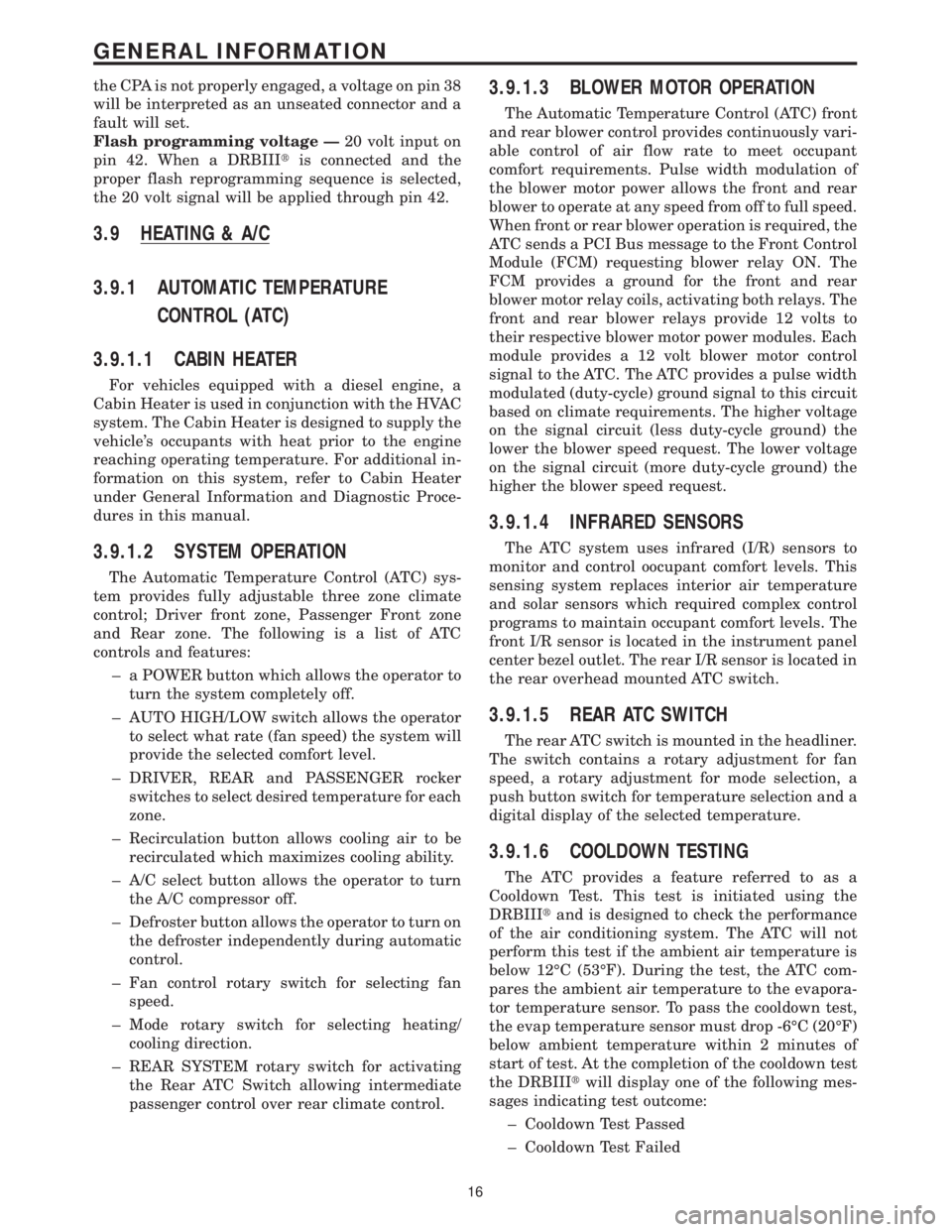
the CPA is not properly engaged, a voltage on pin 38
will be interpreted as an unseated connector and a
fault will set.
Flash programming voltage Ð20 volt input on
pin 42. When a DRBIIItis connected and the
proper flash reprogramming sequence is selected,
the 20 volt signal will be applied through pin 42.
3.9 HEATING & A/C
3.9.1 AUTOMATIC TEMPERATURE
CONTROL (ATC)
3.9.1.1 CABIN HEATER
For vehicles equipped with a diesel engine, a
Cabin Heater is used in conjunction with the HVAC
system. The Cabin Heater is designed to supply the
vehicle's occupants with heat prior to the engine
reaching operating temperature. For additional in-
formation on this system, refer to Cabin Heater
under General Information and Diagnostic Proce-
dures in this manual.
3.9.1.2 SYSTEM OPERATION
The Automatic Temperature Control (ATC) sys-
tem provides fully adjustable three zone climate
control; Driver front zone, Passenger Front zone
and Rear zone. The following is a list of ATC
controls and features:
± a POWER button which allows the operator to
turn the system completely off.
± AUTO HIGH/LOW switch allows the operator
to select what rate (fan speed) the system will
provide the selected comfort level.
± DRIVER, REAR and PASSENGER rocker
switches to select desired temperature for each
zone.
± Recirculation button allows cooling air to be
recirculated which maximizes cooling ability.
± A/C select button allows the operator to turn
the A/C compressor off.
± Defroster button allows the operator to turn on
the defroster independently during automatic
control.
± Fan control rotary switch for selecting fan
speed.
± Mode rotary switch for selecting heating/
cooling direction.
± REAR SYSTEM rotary switch for activating
the Rear ATC Switch allowing intermediate
passenger control over rear climate control.
3.9.1.3 BLOWER MOTOR OPERATION
The Automatic Temperature Control (ATC) front
and rear blower control provides continuously vari-
able control of air flow rate to meet occupant
comfort requirements. Pulse width modulation of
the blower motor power allows the front and rear
blower to operate at any speed from off to full speed.
When front or rear blower operation is required, the
ATC sends a PCI Bus message to the Front Control
Module (FCM) requesting blower relay ON. The
FCM provides a ground for the front and rear
blower motor relay coils, activating both relays. The
front and rear blower relays provide 12 volts to
their respective blower motor power modules. Each
module provides a 12 volt blower motor control
signal to the ATC. The ATC provides a pulse width
modulated (duty-cycle) ground signal to this circuit
based on climate requirements. The higher voltage
on the signal circuit (less duty-cycle ground) the
lower the blower speed request. The lower voltage
on the signal circuit (more duty-cycle ground) the
higher the blower speed request.
3.9.1.4 INFRARED SENSORS
The ATC system uses infrared (I/R) sensors to
monitor and control oocupant comfort levels. This
sensing system replaces interior air temperature
and solar sensors which required complex control
programs to maintain occupant comfort levels. The
front I/R sensor is located in the instrument panel
center bezel outlet. The rear I/R sensor is located in
the rear overhead mounted ATC switch.
3.9.1.5 REAR ATC SWITCH
The rear ATC switch is mounted in the headliner.
The switch contains a rotary adjustment for fan
speed, a rotary adjustment for mode selection, a
push button switch for temperature selection and a
digital display of the selected temperature.
3.9.1.6 COOLDOWN TESTING
The ATC provides a feature referred to as a
Cooldown Test. This test is initiated using the
DRBIIItand is designed to check the performance
of the air conditioning system. The ATC will not
perform this test if the ambient air temperature is
below 12ÉC (53ÉF). During the test, the ATC com-
pares the ambient air temperature to the evapora-
tor temperature sensor. To pass the cooldown test,
the evap temperature sensor must drop -6ÉC (20ÉF)
below ambient temperature within 2 minutes of
start of test. At the completion of the cooldown test
the DRBIIItwill display one of the following mes-
sages indicating test outcome:
± Cooldown Test Passed
± Cooldown Test Failed
16
GENERAL INFORMATION
Page 59 of 4284

WARNING: BEFORE ROAD TESTING A
VEHICLE, BE SURE THAT ALL
COMPONENTS ARE REASSEMBLED.
DURING THE TEST DRIVE, DO NOT TRY TO
READ THE DRBIIITSCREEN WHILE IN
MOTION. DO NOT HANG THE DRBIIITFROM
THE REAR VIEW MIRROR OR OPERATE IT
YOURSELF. HAVE AN ASSISTANT
AVAILABLE TO OPERATE THE DRBIIIT.
5.0 REQUIRED TOOLS AND
EQUIPMENT
DRBIIIt(diagnostic read-out box)
Jumper wires
Ohmmeter
Voltmeter
Sentry Key Tester
Test Light
8310 Airbag System Load Tool
8443 SRS Airbag System Load Tool
Diagnostic Junction Port Tester 8339
6.0 GLOSSARY OF TERMS
ABSantilock brake system
ACMairbag control module
AECMairbag electronic control module
(ACM)
ASDMairbag system diagnostic module
(ACM)
AT Cautomatic temperature control
BCMbody control module
CABcontroller antilock brake
CMTCcompass/mini-trip computer
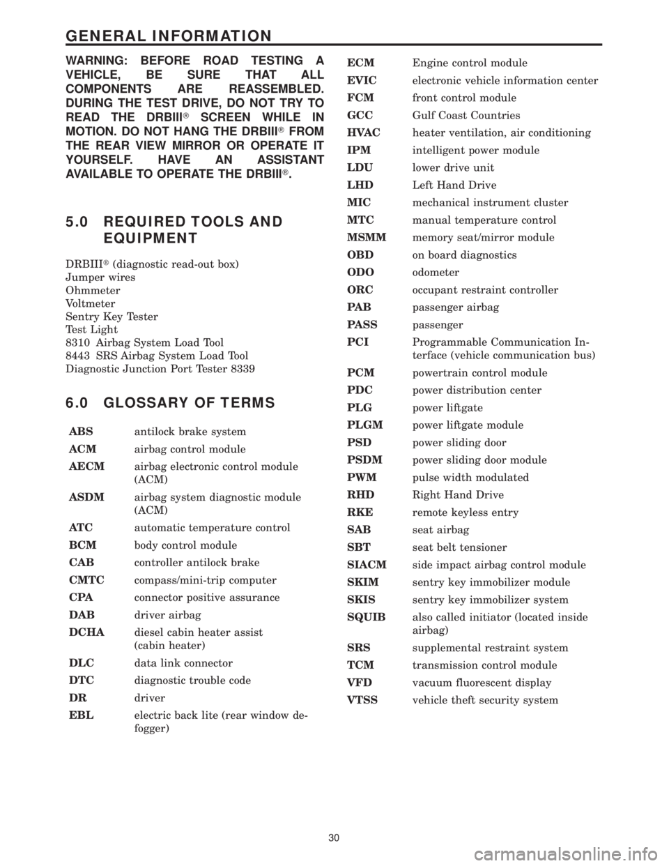
CPAconnector positive assurance
DABdriver airbag
DCHAdiesel cabin heater assist
(cabin heater)
DLCdata link connector
DTCdiagnostic trouble code
DRdriver
EBLelectric back lite (rear window de-
fogger)ECMEngine control module
EVICelectronic vehicle information center
FCMfront control module
GCCGulf Coast Countries
HVACheater ventilation, air conditioning
IPMintelligent power module
LDUlower drive unit
LHDLeft Hand Drive
MICmechanical instrument cluster
MTCmanual temperature control
MSMMmemory seat/mirror module
OBDon board diagnostics
ODOodometer
ORCoccupant restraint controller
PA Bpassenger airbag
PASSpassenger
PCIProgrammable Communication In-
terface (vehicle communication bus)
PCMpowertrain control module
PDCpower distribution center
PLGpower liftgate
PLGMpower liftgate module
PSDpower sliding door
PSDMpower sliding door module
PWMpulse width modulated
RHDRight Hand Drive
RKEremote keyless entry
SABseat airbag
SBTseat belt tensioner
SIACMside impact airbag control module
SKIMsentry key immobilizer module
SKISsentry key immobilizer system
SQUIBalso called initiator (located inside
airbag)
SRSsupplemental restraint system
TCMtransmission control module
VFDvacuum fluorescent display
VTSSvehicle theft security system
30
GENERAL INFORMATION
Page 654 of 4284

Symptom:
CPA NOT ENGAGED
When Monitored and Set Condition:
CPA NOT ENGAGED
When Monitored: Continuously with the ignition on.
Set Condition: If the connector positive assurance lock is not fully engaged, the Front
Control Module will detect battery voltage on the B(+) Sense circuit. With voltage present,
the FCM determines that there is a poor connection at connector C5 of the Fuse and Relay
Center.
POSSIBLE CAUSES
FRONT CONTROL MODULE INTERNAL MALFUNCTION
FUSE AND RELAY CENTER INTERNAL MALFUNCTION
INTERMITTENT CONDITION
CONNECTOR POSITIVE ASSURANCE LOCK
TEST ACTION APPLICABILITY
1 Turn the ignition on.
With the DRBIIIt, erase the current Front Control Module DTC's.
Turn the ignition off, wait 10 seconds then turn the ignition on.
With the DRBIIIt, read the current Front Control Module DTC's.
Does the DRBIIItdisplay: CPA NOT ENGAGED?All
Ye s®Go To 2
No®The condition that caused this symptom is currently not present.
Inspect the related wiring harness for a possible intermittent
condition.
Perform BODY VERIFICATION TEST - VER 1.
2 Turn the ignition off.
Disconnect the Front Control Module from the Fuse and Relay Center.
Measure the voltage of the B(+) Sense circuit at the Fuse and Relay Center side of the
FCM connector.
Is the voltage above 10.0 volts?All
Ye s®Go To 3
No®Replace the Front Control Module.
Perform BODY VERIFICATION TEST - VER 1.
625
INTELLIGENT POWER MODULE
Page 655 of 4284

TEST ACTION APPLICABILITY
3 Turn the ignition off.
Inspect connector C5 on the Fuse and Relay Center, ensure the connector lock is
properly seated into the connector.
Measure the voltage of the B(+) Sense circuit at the Fuse and Relay Center side of the
FCM connector.
Is the voltage above 10.0 volts?All
Ye s®Replace the Fuse and Relay Center.
Perform BODY VERIFICATION TEST - VER 1.
No®Verify the Connector Positive Assurance lock is correctly seated.
Perform BODY VERIFICATION TEST - VER 1.
626
INTELLIGENT POWER MODULE
CPA NOT ENGAGED ÐContinued