2001 CHRYSLER VOYAGER warning light
[x] Cancel search: warning lightPage 1984 of 4284
POWER LIFTGATE SYSTEM INHIBITORS
²The Power Liftgate may not operate in extreme
temperatures. These extreme temperatures will be
approximately -12É F (-24.4É C) on the low side and
143É F (61.6É C) for the high side. A chime/thermister
assembly in the rear light bar assembly monitors the
outside temperature.
²The vehicles transmission must be in park or
neutral for the power liftgate to start a cycle.
²If multiple obstacles are detected during the
same power open or close cycle the liftgate goes into
manual operation.
²If severe Diagnostic Trouble Codes (DTC) are
stored in the power liftgate control module.
POWER LIFTGATE SYSTEM CAUTIONS AND
WARNINGS
WARNING: ALWAYS DISCONNECT THE NEGATIVE
BATTERY CABLE BEFORE ATTEMPTING ANY
POWER LIFTGATE SYSTEM SERVICE.
WARNING: THERE IS A SMALL AREA ON BOTH
SIDES OF THE LOWER POWER LIFTGATE WHICH
ARE NOT PROTECTED BY PINCH SENSORS.
EXTREME CARE MUST BE TAKEN TO PREVENT
OBJECTS FROM ENTERING THIS AREA ONCE THE
LIFTGATE REACHES THE SECONDARY LATCH
CONTACT (APPROXIMATELY 1/2 INCH BEFORE
FULLY CLOSED).
WARNING: NEVER ATTEMPT TO ENTER OR EXIT
THE VEHICLE WITH THE LIFTGATE IN MOTION.
YOU COULD DAMAGE THE POWER LIFTGATE SYS-
TEM AND/OR COMPONENTS AND/OR CAUSE PER-
SONAL INJURY.
WARNING: NEVER STICK OBJECTS IN THE POWER
LIFTGATE WHEN CINCHING CLOSED. YOU COULDDAMAGE THE VEHICLE, POWER LIFTGATE SYS-
TEM COMPONENTS AND/OR CAUSE PERSONAL
INJURY.
DIAGNOSIS AND TESTING - POWER LIFTGATE
SYSTEM
The power opening and closing power liftgate sys-
tem is a complex system containing many compo-
nents and modules. In order to obtain conclusive
testing the Programmable Communications Interface
(J1850) data bus network and all of the electronic
modules that provide inputs to, or receive outputs
from the power liftgate system must be checked.
The power liftgate system was designed to be diag-
nosed with an appropriate diagnostic scan tool, such
as the DRB IIIt. The most reliable, efficient, and
accurate means to diagnose the power liftgate system
requires the use of a DRB IIItscan tool and the
proper Body Diagnostic Procedures manual. The
DRB IIItcan be used to observe various switch sta-
tuses throughout the power liftgate system to help
the technician diagnose a defective switch or compo-
nent. The DRB IIItcan also be used to actuate var-
ious components throughout the power liftgate
system to help the technician diagnose a defective
component.
Before any testing of the power liftgate system is
attempted, the battery should be fully charged, all
built-in power liftgate system inhibitors read and
understood (Refer to power liftgate system operation)
and all wire harness and ground connections
inspected around the affected areas on the vehicle.
Following are quick reference diagnostic tables to
help when diagnosing and testing the power liftgate
system.
8N - 4 POWER LIFTGATE SYSTEMRS
POWER LIFTGATE SYSTEM (Continued)
Page 2027 of 4284
The driver side automatic dimming mirror is stan-
dard with the automatic dimming inside mirror. The
signal to control the dimming of that mirror is gen-
erated by the automatic day/night inside rear view
mirror circuitry. That signal is then delivered to the
driver side outside rear view mirror on a hard wired
circuit.
The automatic day/night mirror cannot be
repaired. If faulty or damaged, the entire inside rear
view mirror assembly must be replaced.
DIAGNOSIS AND TESTING - AUTOMATIC
DAY/NIGHT MIRROR
For circuit descriptions and diagrams, refer to the
appropriate wiring information. The wiring informa-
tion includes wiring diagrams, proper wire and con-
nector repair procedures, details of wire harness
routing and retention, connector pin-out information
and location views for the various wire harness con-
nectors, splices and grounds.
(1) Check the fuse in the intelligent power module.
If OK, go to Step 2. If not OK, repair the shorted cir-
cuit or component as required and replace the faulty
fuse.
(2) Turn the ignition switch to the On position.
Check for battery voltage at the fuse in the intelli-
gent power module. If OK, go to Step 3. If not OK,
repair the open circuit to the ignition switch as
required.
(3) Unplug the wire harness connector from the
automatic day/night mirror. Check for battery voltage
at the fused ignition switch output circuit cavity of
the automatic day/night mirror wire harness connec-
tor. If OK, go to Step 4. If not OK, repair the open
circuit to the junction block as required.
(4) Turn the ignition switch to the Off position.
Check for continuity between the ground circuit cav-
ity of the automatic day/night mirror wire harness
connector and a good ground. There should be conti-
nuity. If OK, go to Step 5. If not OK, repair the cir-
cuit to ground as required.
(5) Turn the ignition switch to the On position. Set
the parking brake. Place the transmission gear selec-
tor lever in the Reverse position. Check for battery
voltage at the backup lamp switch output circuit cav-ity of the automatic day/night mirror wire harness
connector. If voltage is present, reinstall the auto-
matic day/night mirror wire harness connector and
go to Step 6. If not OK, repair the open circuit as
required.
(6) Place the transmission gear selector lever in
the Neutral position. Place the automatic day/night
mirror switch in the On (LED in the switch is
lighted) position. Cover the forward facing ambient
photocell sensor to keep out any ambient light.
NOTE: The ambient photocell sensor must be cov-
ered completely, so that no light reaches the sen-
sor. Use a finger pressed tightly against the sensor,
or cover the sensor completely with electrical tape.
(7) Shine a light into the rearward facing head-
lamp photocell sensor. The automatic day/night mir-
ror should darken. The automatic day/night mirror
should darken within 2 minutes if testing for the
first time. For immediate response, turn the vehicle
OFF and back ON with the forward-facing light sen-
sor still covered. This defeats the day-detect logic. If
OK, go to Step 8. If not OK, replace the faulty mirror
unit.
(8) With the mirror darkened, place the transmis-
sion gear selector lever in the Reverse position. The
automatic day/night mirror should return to its nor-
mal reflectance. If not OK, replace the faulty mirror
unit.
Bench testing both mirrors can be done, of care is
exercised. For an inside mirror, the pin closest to he
mount is 12V (+), the next is 12V (-). The third is
reverse override. The fourth is outside mirror (+),
and the fifth is outside mirror (-).Do not apply 12
volts to the fourth and fifth pins.With 12 volts
on pins 1 and 2, the mirror can be tested by blocking
the rear sensor and shining a light into the forward
sensor. For an outside mirror, there is a 2±pin con-
nector. Applying 1.2 volts will cause the mirror to
dim. If the mirror does not dim, the entire glass
assembly can be replaced just as it is when the glass
is broken.
WARNING: Do not apply 12 volts to the outside mir-
ror. Damage to the mirror will result.
RSPOWER MIRRORS8N-47
AUTOMATIC DAY / NIGHT MIRROR (Continued)
Page 2049 of 4284
AIRBAG SQUIB STATUS
(1) Using a DRBIIItread Airbag DTC's
Ifthe following active codes are present:
DTC CONDITIONS ACTIVE SQUIB
Driver Squib 1 openAND IFthe stored minutes for both are within 15
minutes of each other, both Driver Squib 1 and 2 were
used.Both Driver Squib 1 and
2 were used.
Driver Squib 2 open
Driver Squib 1 openAND IFthe stored minutes for Driver Squib 2 open is
GREATER than the stored minutes for Driver Squib 1
by 15 minutes or more.Driver Squib 1 was used;
Driver Squib 2 is live.
Driver Squib 2 open
Driver Squib 1 openAND IFthe stored minutes for Driver Squib 1 open is
GREATER than the stored minutes for Driver Squib 2
by 15 minutes or more.Driver Squib 1 is live;
Driver Squib 2 was used.
Driver Squib 2 open
IfDriver Squib 1 open is
an active codeAND IFDriver Squib 2 open is NOT an active code.Driver Squib 1 was used;
Driver Squib 2 is live.
IfDriver Squib 2 open is
an active codeAND IFDriver Squib 1 open is NOT an active code.Driver Squib 1 is live;
Driver Squib 2 was used.
Ifneither of the following codes is an active code:
DTC ACTIVE SQUIB
Driver squib 1 open
Status of Airbag is
Unknown.
Driver squib 2 open
NOTE: If the Driver/Passenger Airbag is defective
and not deployed, refer to DaimlerChrysler Motors
Corporation current return policies for proper han-
dling procedures.
DIAGNOSIS AND TESTING - AIRBAG SYSTEM
(1) Connect a DRBIIItscan tool to the Data Link
Connector (DLC), located at left side of the steering
column and at the lower edge of the lower instru-
ment panel.
(2) Turn the ignition key to ON position. Exit vehi-
cle with scan tool. Use the latest version of the
proper cartridge.
(3) After checking that no one is inside the vehicle,
connect the battery negative terminal.
(4) Using the DRBIIItscan tool, read and record
active diagnostic code data.
(5) Read and record any stored diagnostic codes.
(6) Refer to the proper Body Diagnostic Procedures
manual if any diagnostic codes are found in Step 4 or
Step 5.
(7) Erase stored diagnostic codes if there are no
active diagnostic codes. If problems remain, diagnos-
tic codes will not erase. Refer to the Proper Body
Diagnostic Procedures Manual to diagnose the prob-
lem.If airbag warning lamp either fails to light,
or goes on and stays on, there is a system mal-function. Refer to the proper Body Diagnostic
Procedures manual to diagnose the problem.
CLOCK SPRING
DESCRIPTION
The clock spring is screwed to a plastic mounting
platform on the steering column behind the steering
wheel. The clock spring is used to maintain a contin-
uous electrical circuit between the wiring harness
and the drivers airbag.
OPERATION
This assembly consists of a flat ribbon like electri-
cally conductive tape which winds and unwinds with
the steering wheel rotation. The clock spring cannot
be repaired. If the clock spring is faulty, damaged, or
if the airbag has been deployed, the clock spring
must be replaced.
STANDARD PROCEDURE - CLOCK SPRING
CENTERING
If the rotating tape (wire coil) in the clock spring is
not positioned properly with the steering wheel and
the front wheels, the clock spring may fail. The fol-
lowing procedure MUST BE USED to center the
clock spring if it is not known to be properly posi-
tioned, or if the front wheels were moved from the
straight ahead position.
(1) Adjust the steering wheel so that the tires are
in a straight ahead position.
(2) Remove Driver Airbag from steering wheel.
(3) Disconnect wire connectors from back of airbag.
RSRESTRAINTS8O-3
RESTRAINTS (Continued)
Page 2051 of 4284
The components above must be replaced because
they cannot be reused. Replace any other driver air-
bag system components if damaged.
REMOVAL
DEPLOYED AIRBAG
The Driver Airbag and Driver Airbag Cover/Horn
Pad are serviced separately from each other.
(1) Clean powder residue from interior of vehicle,
(Refer to 8 - ELECTRICAL/RESTRAINTS/DRIVER
AIRBAG - STANDARD PROCEDURE ) Cleanup.
(2) Remove two screws attaching Driver Airbag to
steering wheel.
(3) Remove the driver airbag from steering wheel.
(4) Disconnect wire connectors from Airbag and
Clock Spring.
(5) Adjust the steering wheel so that the tires are
in a straight ahead position. Remove steering wheel,
(Refer to 19 - STEERING/COLUMN/STEERING
WHEEL - REMOVAL)
(6) Disconnect the 2-way and 4-way connectors
between the clock spring and the instrument panel
wiring harness.
(7) Remove upper and lower steering column
shrouds.
(8) Remove clock spring from the housing assem-
bly by depressing the 2 tabs on the clock spring.
UNDEPLOYED AIRBAG
(1) Remove screws attaching airbag/horn switch to
steering wheel.
(2) Remove Driver Airbag from steering wheel.
(3) Disconnect wire connectors from driver airbag
and clock spring.
INSTALLATION
DEPLOYED AIRBAG
(1) Perform cleanup procedure.(Refer to 8 - ELEC-
TRICAL/RESTRAINTS/DRIVER AIRBAG - STAN-
DARD PROCEDURE)
(2) Install a new steering column assembly and
lower steering column coupler. Refer to Steering, Col-
umn, Installation.
(3) Install the clock spring.
(4) Install the driver airbag and the two screws
retaining the airbag. Tighten screws to 10 N´m (90
in. lbs.)
WARNING: DO NOT CONNECT THE BATTERY NEGA-
TIVE CABLE. REFER TO ELECTRICAL, RESTRAINTS,
DIAGNOSIS AND TESTING - AIRBAG SYSTEM FIRST.
UNDEPLOYED AIRBAG
(1) Position a new airbag into the airbag cavity.(2) Install the two screws retaining the airbag.
Tighten screws to 10 N´m (90 in. lbs.)
WARNING: DO NOT CONNECT THE BATTERY NEGA-
TIVE CABLE. REFER TO ELECTRICAL, RESTRAINTS,
DIAGNOSIS AND TESTING - AIRBAG SYSTEM FIRST.
OCCUPANT RESTRAINT
CONTROLLER
DESCRIPTION
The front driver and passenger airbag system is
designed to reduce the risk of fatality or serious
injury, caused by a frontal impact of the vehicle.
The Occupant Restraint Controller (ORC) contains
the impact sensor and energy reserve capacitor. It is
mounted on a bracket, under the instrument panel,
just forward of the storage bin. The ORC monitors
the system to determine the system readiness. The
ORC contains on-board diagnostics and will light the
AIRBAG warning lamp in the message center when a
problem occurs.
OPERATION
The impact sensor provides verification of the
direction and severity of the impact. One impact sen-
sor is used. It is located inside the Occupant
Restraint Controller (ORC). The impact sensor is an
accelerometer that senses deceleration. The decelera-
tion pulses are sent to a microprocessor which con-
tains a decision algorithm. When an impact is severe
enough to require airbag protection, the ORC micro-
processor sends a signal that completes the electrical
circuit to the driver and passenger airbags. The
impact sensor is calibrated for the specific vehicle
and reacts to the severity and direction of an impact.
REMOVAL
(1)Disconnect and isolate the battery negative cable.
(2) Remove storage bin from instrument panel.
Refer to Body, Instrument Panel, Storage Bin,
Removal.
(3) Remove three bolts holding ORC to floor
bracket.
(4) Disconnect the wire connector from ORC.
(5) Remove the ORC w/bracket assembly from
vehicle.
INSTALLATION
WARNING: DO NOT INSTALL ORC IF MOUNTING
LOCATION IS DEFORMED OR DAMAGED.
RSRESTRAINTS8O-5
DRIVER AIRBAG (Continued)
Page 2851 of 4284
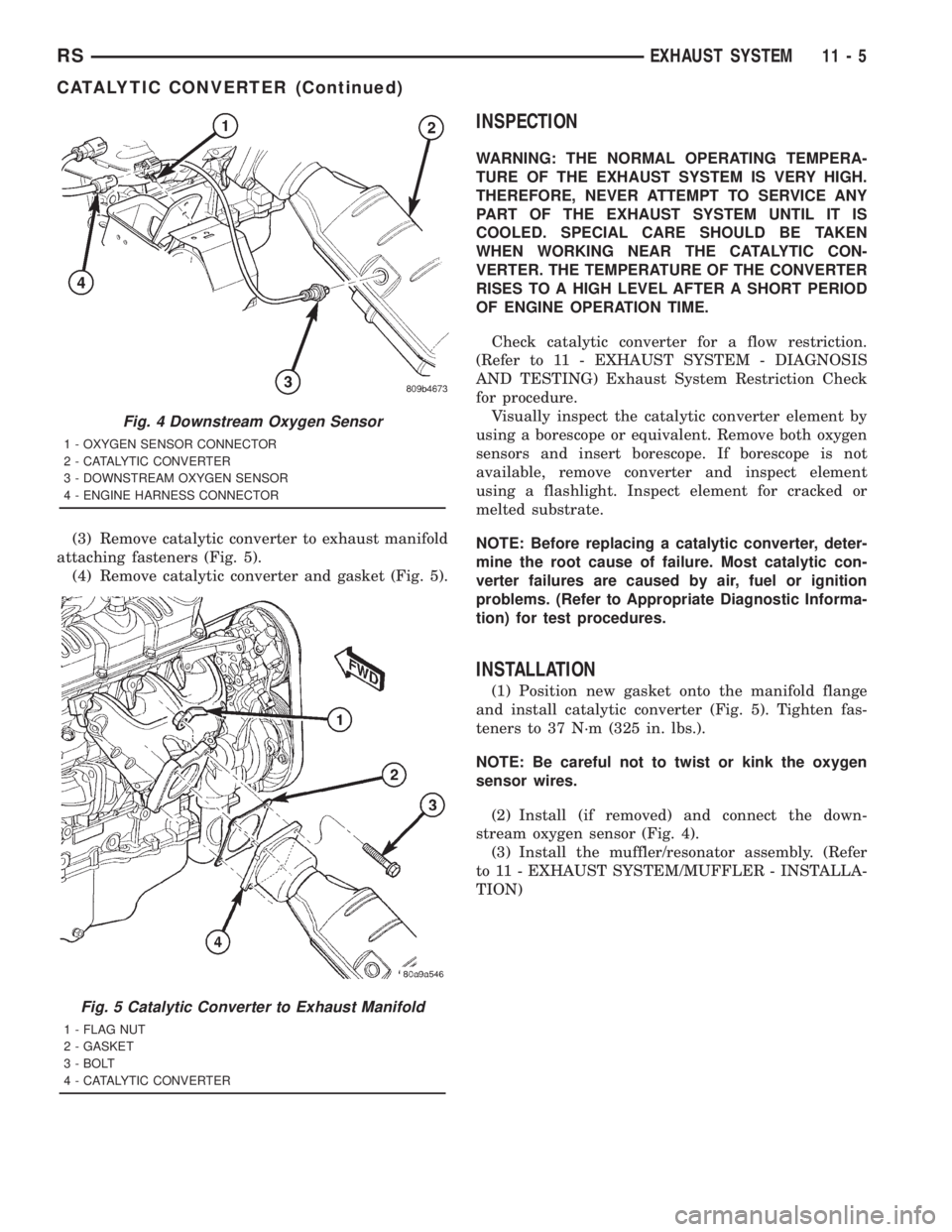
(3) Remove catalytic converter to exhaust manifold
attaching fasteners (Fig. 5).
(4) Remove catalytic converter and gasket (Fig. 5).
INSPECTION
WARNING: THE NORMAL OPERATING TEMPERA-
TURE OF THE EXHAUST SYSTEM IS VERY HIGH.
THEREFORE, NEVER ATTEMPT TO SERVICE ANY
PART OF THE EXHAUST SYSTEM UNTIL IT IS
COOLED. SPECIAL CARE SHOULD BE TAKEN
WHEN WORKING NEAR THE CATALYTIC CON-
VERTER. THE TEMPERATURE OF THE CONVERTER
RISES TO A HIGH LEVEL AFTER A SHORT PERIOD
OF ENGINE OPERATION TIME.
Check catalytic converter for a flow restriction.
(Refer to 11 - EXHAUST SYSTEM - DIAGNOSIS
AND TESTING) Exhaust System Restriction Check
for procedure.
Visually inspect the catalytic converter element by
using a borescope or equivalent. Remove both oxygen
sensors and insert borescope. If borescope is not
available, remove converter and inspect element
using a flashlight. Inspect element for cracked or
melted substrate.
NOTE: Before replacing a catalytic converter, deter-
mine the root cause of failure. Most catalytic con-
verter failures are caused by air, fuel or ignition
problems. (Refer to Appropriate Diagnostic Informa-
tion) for test procedures.
INSTALLATION
(1) Position new gasket onto the manifold flange
and install catalytic converter (Fig. 5). Tighten fas-
teners to 37 N´m (325 in. lbs.).
NOTE: Be careful not to twist or kink the oxygen
sensor wires.
(2) Install (if removed) and connect the down-
stream oxygen sensor (Fig. 4).
(3) Install the muffler/resonator assembly. (Refer
to 11 - EXHAUST SYSTEM/MUFFLER - INSTALLA-
TION)
Fig. 4 Downstream Oxygen Sensor
1 - OXYGEN SENSOR CONNECTOR
2 - CATALYTIC CONVERTER
3 - DOWNSTREAM OXYGEN SENSOR
4 - ENGINE HARNESS CONNECTOR
Fig. 5 Catalytic Converter to Exhaust Manifold
1 - FLAG NUT
2 - GASKET
3 - BOLT
4 - CATALYTIC CONVERTER
RSEXHAUST SYSTEM11-5
CATALYTIC CONVERTER (Continued)
Page 2949 of 4284
SERVICE WARNINGS AND CAUTIONS
WARNING: POWER STEERING FLUID, ENGINE
PARTS AND EXHAUST SYSTEM MAY BE
EXTREMELY HOT IF ENGINE HAS BEEN RUNNING.
DO NOT START ENGINE WITH ANY LOOSE OR DIS-
CONNECTED HOSES. DO NOT ALLOW HOSES TO
TOUCH HOT EXHAUST MANIFOLD OR CATALYST.
WARNING: FLUID LEVEL SHOULD BE CHECKED
WITH THE ENGINE OFF TO PREVENT PERSONAL
INJURY FROM MOVING PARTS.
CAUTION: When the system is open, cap all open
ends of the hoses, power steering pump fittings or
power steering gear ports to prevent entry of for-
eign material into the components.
STANDARD PROCEDURE - POWER STEERING
PUMP INITIAL OPERATION
CAUTION: The fluid level should be checked with
engine off to prevent injury from moving compo-
nents. Use only MoparTPower Steering Fluid (MS-
5931) or approved equivalent. Do not overfill.
Read the fluid level through the side of the power
steering fluid reservoir. The fluid level should indi-
cateªFILL RANGEºwhen the fluid is at a temper-
ature of approximately 21ÉC to 27ÉC (70ÉF to 80ÉF).
(1) Wipe the filler cap and area clean, then remove
the cap.
(2) Fill the fluid reservoir to the proper level and
let the fluid settle for at least two (2) minutes.
(3) Start the engine and let run for a few seconds,
then turn the engine off.
(4) Add fluid if necessary. Repeat the above steps
until the fluid level remains constant after running
the engine.
(5) Raise the front wheels off the ground.
(6) Start the engine.
(7) Slowly turn the steering wheel right and left,
lightly contacting the wheel stops.
(8) Add fluid if necessary.
(9) Lower the vehicle, then turn the steering wheel
slowly from lock-to-lock.
(10) Stop the engine. Check the fluid level and
refill as required.
(11) If the fluid is extremely foamy, allow the vehi-
cle to stabilize a few minutes, then repeat the above
procedure.
REMOVAL - PUMP (2.4L ENGINE)
(1) Remove the (-) negative battery cable from the
battery and isolate cable.
(2) Remove the cap from the power steering fluid
reservoir.
(3) Using a siphon pump, remove as much power
steering fluid as possible from the power steering
fluid reservoir.
(4) Raise the vehicle on jack stands or centered on
a frame contact type hoist. See Hoisting in Lubrica-
tion and Maintenance.
(5) Disconnect the oxygen sensor wiring harness
from the vehicle wiring harness at the rear engine
mount bracket.
NOTE: The exhaust system needs to be removed
from the engine to allow for an area to remove the
power steering pump from the vehicle.
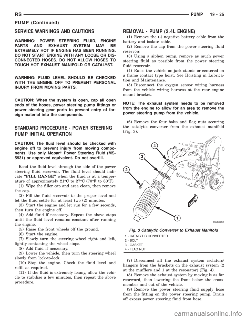
(6) Remove the four bolts and flag nuts securing
the catalytic converter from the exhaust manifold
(Fig. 3).
(7) Disconnect all the exhaust system isolators/
hangers from the brackets on the exhaust system (2
at the mufflers and 1 at the resonator) (Fig. 4).
(8) Remove the exhaust system by moving it as far
rearward, then lowering the front below the cross-
member and out of the vehicle.
(9) Remove the power steering fluid supply hose
from the fitting on the power steering pump. Drain
off excess power steering fluid from hose.
Fig. 3 Catalytic Converter to Exhaust Manifold
1 - CATALYTIC CONVERTER
2 - BOLT
3 - GASKET
4 - FLAG NUT
RSPUMP19-25
PUMP (Continued)
Page 3381 of 4284
BODY
TABLE OF CONTENTS
page page
BODY
DESCRIPTION............................1
WARNING...............................2
DIAGNOSIS AND TESTING..................2
WATER LEAKS..........................2
WIND NOISE...........................3
STANDARD PROCEDURE...................4
PLASTIC BODY PANEL REPAIR.............4
HEAT STAKING.........................8
SPECIFICATIONS.........................9
SPECIAL TOOLS........................151DOOR - FRONT.........................152
DOORS - SLIDING.......................162
DECKLID/HATCH/LIFTGATE/TAILGATE.......180
EXTERIOR.............................184
HOOD................................199
INSTRUMENT PANEL....................202
INTERIOR.............................208
PAINT................................220
SEATS................................222
STATIONARY GLASS.....................243
WEATHERSTRIP/SEALS..................248
BODY
DESCRIPTION - LOCK CYLINDERS
Ignition, door, deck lid, and rear hatch lock cylin-
ders are all codable to the key. Lock barrels, tum-
blers, and tumbler springs are available to allow the
technician to change replacement locks cylinders to
match the customer's original key set. See the appro-
priate section in this manual for lock cylinder
removal. See the Moparž catalogue for part numbers
and lock coding procedures.
DESCRIPTION - VEHICLE IDENTIFICATION
Throughout this group, references to the
DaimlerChrysler Corporation vehicle family identifi-
cation code are used when describing a procedure
that is unique to that vehicle. Refer to Introduction
Group of this manual for detailed information on
vehicle identification. If a procedure is common to all
vehicles covered in this manual, no reference will be
made to a vehicle family code.
DESCRIPTION - PUSH-IN FASTENERS
DaimlerChrysler Corporation uses many different
types of push-in fasteners to secure the interior and
exterior trim to the body. Most of these fasteners can
be reused to assemble the trim during various repair
procedures. At times, a push-in fastener cannot be
removed without damaging the fastener or the com-
ponent it is holding. If it is not possible to remove a
fastener without damaging a component or body, cut
or break the fastener and use a new one when
installing the component. Never pry or pound on a
plastic or pressed-board trim component. Using a
suitable fork-type prying device, pry the fastener
from the retaining hole behind the component beingremoved. When installing, verify fastener alignment
with the retaining hole by hand. Push directly on or
over the fastener until it seats. Apply a low-force pull
to the panel to verify that it is secure.
When it is necessary to remove components to ser-
vice another, it should not be necessary to apply
excessive force or bend a component to remove it.
Before damaging a trim component, verify hidden
fasteners or captured edges holding the component in
place.
DESCRIPTION
PAINT
The original equipment finish is a multi-step pro-
cess that involves cleaning, electrodeposition (e-coat),
base coat, and clear coat steps. Additionally, selected
areas of the vehicle may be coated with an anti-chip
finish.
On most vehicles a two-stage paint application
(base coat/clear coat) is used. Color that is applied to
primer is called base coat. The clear coat protects the
base coat from ultraviolet light and provides a dura-
ble high-gloss finish.
STATIONARY GLASS
Windshields are made of two pieces of glass with a
plastic inner layer. Windshields and selected station-
ary glass are structural members of the vehicle. The
windshield glass is bonded to the windshield frame
with urethane adhesive.
Windshields and other stationary glass protect the
occupants from the effects of the elements. Wind-
shields are also used to retain some airbags in posi-
tion during deployment. Urethane bonded glass is
difficult to salvage during removal. The urethane
bonding is difficult to cut or clean from any surface.
RSBODY23-1
Page 3382 of 4284
Before removing the glass, check the availability of
replacement components.
SEATS
Seat modules are made up of a seat frame, seat
cushion, seat back cushion, a covering material, and
the electrical components used for power operation, if
equipped. Some seat systems also contain seat belt
components and supplemental restraint systems.
Seat assemblies transport the occupants in comfort
and safety. Seat assemblies also help position occu-
pants correctly in the event of airbag deployment.
Seat cushions, coverings, and electrical components
are serviceable. Refer to the appropriate group in
this manual.
EXTERIOR COMPONENTS
Exterior sheet metal components make up the
exterior of the vehicle. Some exterior metal systems
are welded assemblies, such as doors and hoods.
Some exterior trim items are made of composite.
The exterior is finished in various metal stampings
and composite moldings. These assemblies give the
vehicle a finished appearance and protect the occu-
pants from the elements. Some components are part
of the energy absorbing system used to protect the
occupants in collisions. The exterior sheet metal is
repairable and adjustable for fit and finish. Welded
and bonded component systems are adjustable as a
system. Trim components made of composite are
stamped with the type of material used.
DaimlerChrysler uses various fasteners to retain
trim items. At times, it is not possible to remove trim
items without damaging the fastener. If it is not pos-
sible to remove an item without damaging a compo-
nent, cut or break the fasteners and use new ones
when installing the component.
SAFETY PRECAUTIONS AND WARNINGS
WARNING:
EYE PROTECTION SHOULD BE USED WHEN SER-
VICING GLASS COMPONENTS. PERSONAL INJURY
CAN RESULT.
USE A OSHA APPROVED BREATHING FILTER
WHEN SPRAYING PAINT OR SOLVENTS IN A CON-
FINED AREA. PERSONAL INJURY CAN RESULT.
AVOID PROLONGED SKIN CONTACT WITH PETRO-
LEUM OR ALCOHOL BASED CLEANING SOLVENTS.
PERSONAL INJURY CAN RESULT.
DO NOT STAND UNDER A HOISTED VEHICLE THAT
IS NOT PROPERLY SUPPORTED ON SAFETY
STANDS. PERSONAL INJURY CAN RESULT.
CAUTION:
When holes must be drilled or punched in an innerbody panel, verify depth of space to the outer body
panel, electrical wiring, or other components. Dam-
age to vehicle can result.
Do not weld exterior panels unless combustible
material on the interior of vehicle is removed from
the repair area. Fire or hazardous conditions, can
result.
Always have a fire extinguisher ready for use when
welding.
Disconnect the negative battery cable clamp when
servicing electrical components that are live when
the ignition is OFF. Damage to electrical system can
result.
Do not use abrasive chemicals or compounds on
painted surfaces. Damage to finish can result.
Do not use harsh alkaline based cleaning solvents
on painted or upholstered surfaces. Damage to fin-
ish or color can result.
Do not hammer or pound on plastic trim panel
when servicing interior trim. Plastic panels can
break.
DIAGNOSIS AND TESTING - WATER LEAKS
Water leaks can be caused by poor sealing,
improper body component alignment, body seam
porosity, missing plugs, or blocked drain holes. Cen-
trifugal and gravitational force can cause water to
drip from a location away from the actual leak point,
making leak detection difficult. All body sealing
points should be water tight in normal wet-driving
conditions. Water flowing downward from the front of
the vehicle should not enter the passenger or luggage
compartment. Moving sealing surfaces will not
always seal water tight under all conditions. At
times, side glass or door seals will allow water to
enter the passenger compartment during high pres-
sure washing or hard driving rain (severe) condi-
tions. Overcompensating on door or glass
adjustments to stop a water leak that occurs under
severe conditions can cause premature seal wear and
excessive closing or latching effort. After completing
a repair, water test vehicle to verify leak has stopped
before returning vehicle to use.
VISUAL INSPECTION BEFORE WATER LEAK TESTS
Verify that floor and body plugs are in place, body
drains are clear, and body components are properly
aligned and sealed. If component alignment or seal-
ing is necessary, refer to the appropriate section of
this group for proper procedures.
WATER LEAK TESTS
WARNING: DO NOT USE ELECTRIC SHOP LIGHTS
OR TOOLS IN WATER TEST AREA. PERSONAL
INJURY CAN RESULT.
23 - 2 BODYRS
BODY (Continued)