2001 CHRYSLER VOYAGER warning light
[x] Cancel search: warning lightPage 3732 of 4284
(4) Remove the screw that secures the back of the
rear heater-A/C unit housing to the right D-pillar.
(5) Remove the screw that secures the front of the
rear heater-A/C unit housing to the right quarter
inner panel.
(6) Take the proper precautions to protect the car-
peting below the rear heater core from spilled engine
coolant and have absorbent toweling readily avail-
able to mop up any spills.
(7) Disconnect the heater hoses at the rear heater
core. (Refer to 24 - HEATING & AIR CONDITION-
ING/PLUMBING - REAR/HEATER HOSE - REMOV-
AL).
(8) Install plugs in, or tape over the opened heater
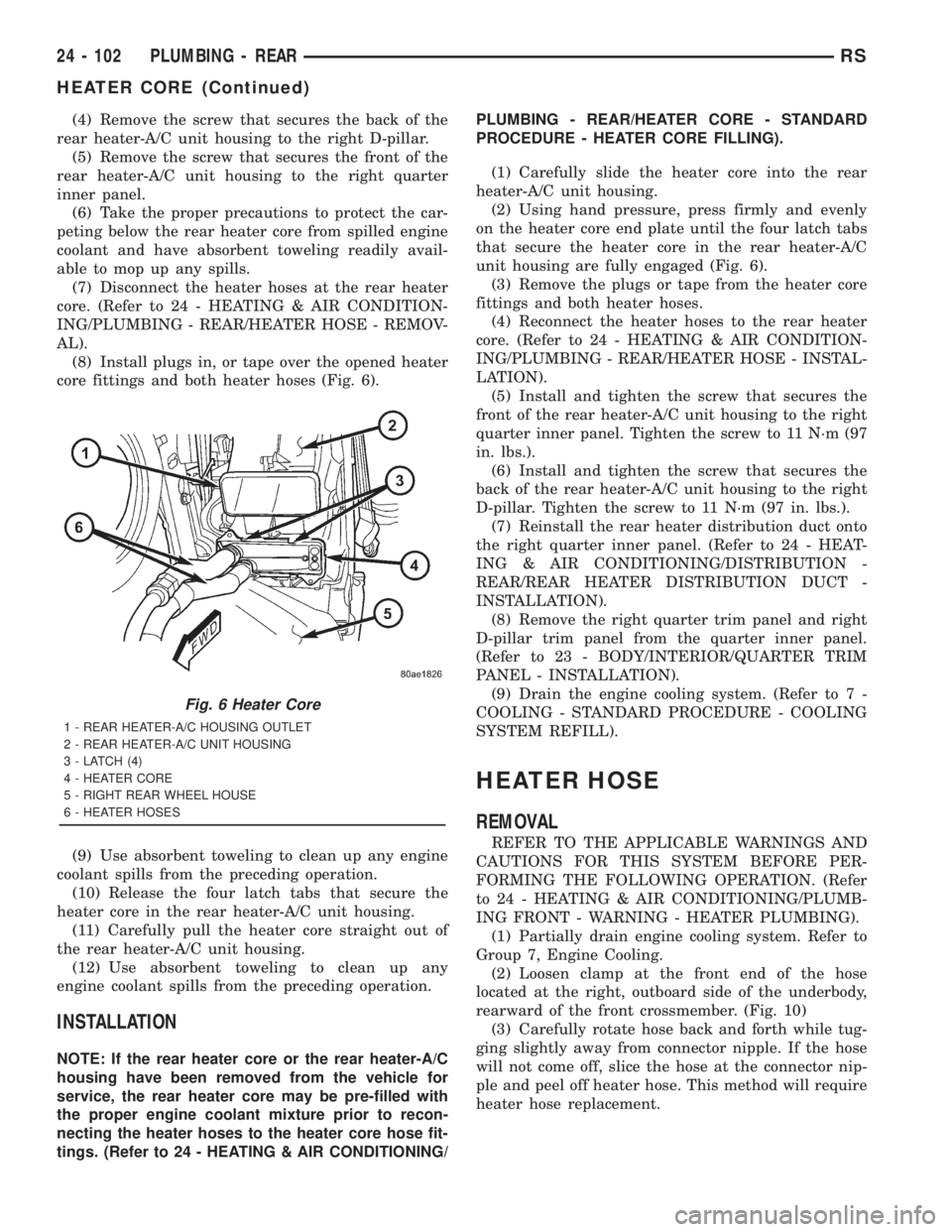
core fittings and both heater hoses (Fig. 6).
(9) Use absorbent toweling to clean up any engine
coolant spills from the preceding operation.
(10) Release the four latch tabs that secure the
heater core in the rear heater-A/C unit housing.
(11) Carefully pull the heater core straight out of
the rear heater-A/C unit housing.
(12) Use absorbent toweling to clean up any
engine coolant spills from the preceding operation.
INSTALLATION
NOTE: If the rear heater core or the rear heater-A/C
housing have been removed from the vehicle for
service, the rear heater core may be pre-filled with
the proper engine coolant mixture prior to recon-
necting the heater hoses to the heater core hose fit-
tings. (Refer to 24 - HEATING & AIR CONDITIONING/PLUMBING - REAR/HEATER CORE - STANDARD
PROCEDURE - HEATER CORE FILLING).
(1) Carefully slide the heater core into the rear
heater-A/C unit housing.
(2) Using hand pressure, press firmly and evenly
on the heater core end plate until the four latch tabs
that secure the heater core in the rear heater-A/C
unit housing are fully engaged (Fig. 6).
(3) Remove the plugs or tape from the heater core
fittings and both heater hoses.
(4) Reconnect the heater hoses to the rear heater
core. (Refer to 24 - HEATING & AIR CONDITION-
ING/PLUMBING - REAR/HEATER HOSE - INSTAL-
LATION).
(5) Install and tighten the screw that secures the
front of the rear heater-A/C unit housing to the right
quarter inner panel. Tighten the screw to 11 N´m (97
in. lbs.).
(6) Install and tighten the screw that secures the
back of the rear heater-A/C unit housing to the right
D-pillar. Tighten the screw to 11 N´m (97 in. lbs.).
(7) Reinstall the rear heater distribution duct onto
the right quarter inner panel. (Refer to 24 - HEAT-
ING & AIR CONDITIONING/DISTRIBUTION -
REAR/REAR HEATER DISTRIBUTION DUCT -
INSTALLATION).
(8) Remove the right quarter trim panel and right
D-pillar trim panel from the quarter inner panel.
(Refer to 23 - BODY/INTERIOR/QUARTER TRIM
PANEL - INSTALLATION).
(9) Drain the engine cooling system. (Refer to 7 -
COOLING - STANDARD PROCEDURE - COOLING
SYSTEM REFILL).
HEATER HOSE
REMOVAL
REFER TO THE APPLICABLE WARNINGS AND
CAUTIONS FOR THIS SYSTEM BEFORE PER-
FORMING THE FOLLOWING OPERATION. (Refer
to 24 - HEATING & AIR CONDITIONING/PLUMB-
ING FRONT - WARNING - HEATER PLUMBING).
(1) Partially drain engine cooling system. Refer to
Group 7, Engine Cooling.
(2) Loosen clamp at the front end of the hose
located at the right, outboard side of the underbody,
rearward of the front crossmember. (Fig. 10)
(3) Carefully rotate hose back and forth while tug-
ging slightly away from connector nipple. If the hose
will not come off, slice the hose at the connector nip-
ple and peel off heater hose. This method will require
heater hose replacement.
Fig. 6 Heater Core
1 - REAR HEATER-A/C HOUSING OUTLET
2 - REAR HEATER-A/C UNIT HOUSING
3 - LATCH (4)
4 - HEATER CORE
5 - RIGHT REAR WHEEL HOUSE
6 - HEATER HOSES
24 - 102 PLUMBING - REARRS
HEATER CORE (Continued)
Page 3767 of 4284
PCV VALVE
DESCRIPTION
The PCV valve contains a spring loaded plunger.
The plunger meters the amount of crankcase vapors
routed into the combustion chamber based on intake
manifold vacuum.
OPERATION
When the engine is not operating or during an
engine backfire, the spring forces the plunger back
against the seat. This prevents vapors from flowing
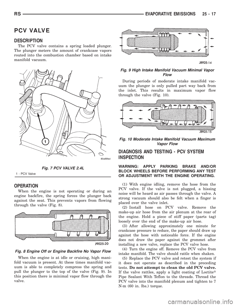
through the valve (Fig. 8).
When the engine is at idle or cruising, high mani-
fold vacuum is present. At these times manifold vac-
uum is able to completely compress the spring and
pull the plunger to the top of the valve (Fig. 9). In
this position there is minimal vapor flow through the
valve.During periods of moderate intake manifold vac-
uum the plunger is only pulled part way back from
the inlet. This results in maximum vapor flow
through the valve (Fig. 10).
DIAGNOSIS AND TESTING - PCV SYSTEM
INSPECTION
WARNING: APPLY PARKING BRAKE AND/OR
BLOCK WHEELS BEFORE PERFORMING ANY TEST
OR ADJUSTMENT WITH THE ENGINE OPERATING.
(1) With engine idling, remove the hose from the
PCV valve. If the valve is not plugged, a hissing
noise will be heard as air passes through the valve. A
strong vacuum should also be felt when a finger is
placed over the valve inlet.
(2) Install hose on PCV valve. Remove the
make-up air hose from the air plenum at the rear of
the engine. Hold a piece of stiff paper (parts tag)
loosely over the end of the make-up air hose.
(3)
After allowing approximately one minute for
crankcase pressure to reduce, the paper should draw up
against the hose with noticeable force. If the engine
does not draw the paper against the grommet after
installing a new valve, replace the PCV valve hose.
(4)Turn the engine off. Remove the PCV valve from
intake manifold. The valve should rattle when shaken.
(5) Replace the PCV valve and retest the system if
it does not operate as described in the preceding
tests.Do not attempt to clean the old PCV valve.
If the valve rattles, apply a light coating of Loctitet
Pipe Sealant With Teflon to the threads. Thread the
PCV valve into the manifold plenum and tighten to 7
N´m (60 in. lbs.) torque.
Fig. 7 PCV VALVE 2.4L
1 - PCV Valve
Fig. 8 Engine Off or Engine Backfire No Vapor Flow
Fig. 9 High Intake Manifold Vacuum Minimal Vapor
Flow
Fig. 10 Moderate Intake Manifold Vacuum Maximum
Vapor Flow
RSEVAPORATIVE EMISSIONS25-17
Page 3804 of 4284
SYMPTOM DIAGNOSTIC TEST
POOR FUEL ECONOMY CHECKING PCM POWER AND GND CKT
CHECKING THE FUEL PRESSURE
CHECKING ECT SENSOR
CHECKING THROTTLE POSITION SENSOR
CHECKING MAP SENSOR
CHECKING IDLE AIR CONTROL MOTOR OPERATION
CHECKING IAT SENSOR
3.4 USING THE DRBIIIT
Refer to the DRBIIItuser 's guide for instructions
and assistance with reading DTC's, erasing DTC's,
and other DRBIIItfunctions.
3.5 DRBIIITERROR MESSAGES AND
BLANK SCREEN
Under normal operation, the DRBIIItwill dis-
play one of only two error messages:
± User-Requested WARM Boot or User-
Requested COLD Boot
ver: 2.14
date: 26 Jul93
file: key_itf.cc
date: Jul 26 1993
line: 548
err: 0x1
User-Requested COLD Boot
Press MORE to switch between this display
and the application screen.
Press F4 when done noting information.
3.5.1 DRBIIITDOES NOT POWER UP
If the LED's do not light or no sound is emitted at
start up, check for loose cable connections or a bad
cable. Check the vehicle battery voltage (data link
connector cavity 16). A minimum of 11 volts is
required to adequately power the DRBIIIt.
If all connections are proper between the
DRBIIItand the vehicle or other devices, and the
vehicle battery is fully charged, and inoperative
DRBIIItmay be the result of faulty cable or vehicle
wiring.
3.5.2 DISPLAY IS NOT VISIBLE
Low temperatures will affect the visibility of the
display. Adjust the contrast to compensate for this
condition
4.0 DISCLAIMERS, SAFETY,
WARNINGS
4.1 DISCLAIMERS
All information, illustrations, and specifications
contained in this manual are based on the latest
information available at the time of publication.
The right is reserved to make changes at any time
without notice.
4.2 SAFETY
4.2.1 TECHNICIAN SAFETY INFORMATION
WARNING: ENGINES PRODUCE CARBON
MONOXIDE THAT IS ODORLESS, CAUSES
SLOWER REACTION TIME, AND CAN LEAD
TO SERIOUS INJURY. WHEN THE ENGINE IS
OPERATING, KEEP SERVICE AREAS WELL
VENTILATED OR ATTACH THE VEHICLE
EXHAUST SYSTEM TO THE SHOP EXHAUST
REMOVAL SYSTEM.
Set the parking brake and block the wheels before
testing or repairing the vehicle. It is especially
10
GENERAL INFORMATION
Page 3816 of 4284
TEST ACTION APPLICABILITY
6 Disconnect the Generator Field harness connector.
Turn the ignition on.
With the DRBIIItactuate the Generator Field Driver.
Using a 12-volt test light connected to ground, probe the ASD Relay Output circuit.
Does the test light illuminate brightly?All
Ye s®Go To 7
No®Repair the ASD Relay Output circuit.
Perform POWERTRAIN VERIFICATION TEST VER - 3.
7 If there is no possible causes remaining, view repair. All
Ye s®Repair or replace the Generator as necessary..
Perform POWERTRAIN VERIFICATION TEST VER - 3.
8WARNING: WHEN THE ENGINE IS OPERATING, DO NOT STAND IN A
DIRECT LINE WITH THE FAN. DO NOT PUT YOUR HANDS NEAR THE
PULLEYS, BELTS OR FAN. DO NOT WEAR LOOSE CLOTHING.
NOTE: The conditions that set the DTC are not present at this time. The
following list may help in identifying the intermittent condition.
With the engine running at normal operating temperature, monitor the DRB
parameters related to the DTC while wiggling the wiring harness. Look for param-
eter values to change and/or a DTC to set.
Review the DRB Freeze Frame information. If possible, try to duplicate the
conditions under which the DTC was set.
Refer to any Technical Service Bulletins (TSB) that may apply.
Visually inspect the related wiring harness. Look for any chafed, pierced, pinched, or
partially broken wires.
Visually inspect the related wiring harness connectors. Look for broken, bent, pushed
out, or corroded terminals.
Were any of the above conditions present?All
Ye s®Repair as necessary
Perform POWERTRAIN VERIFICATION TEST VER - 3.
No®Test Complete.
22
CHARGING
P1682-CHARGING SYSTEM VOLTAGE TOO LOW ÐContinued
Page 3931 of 4284
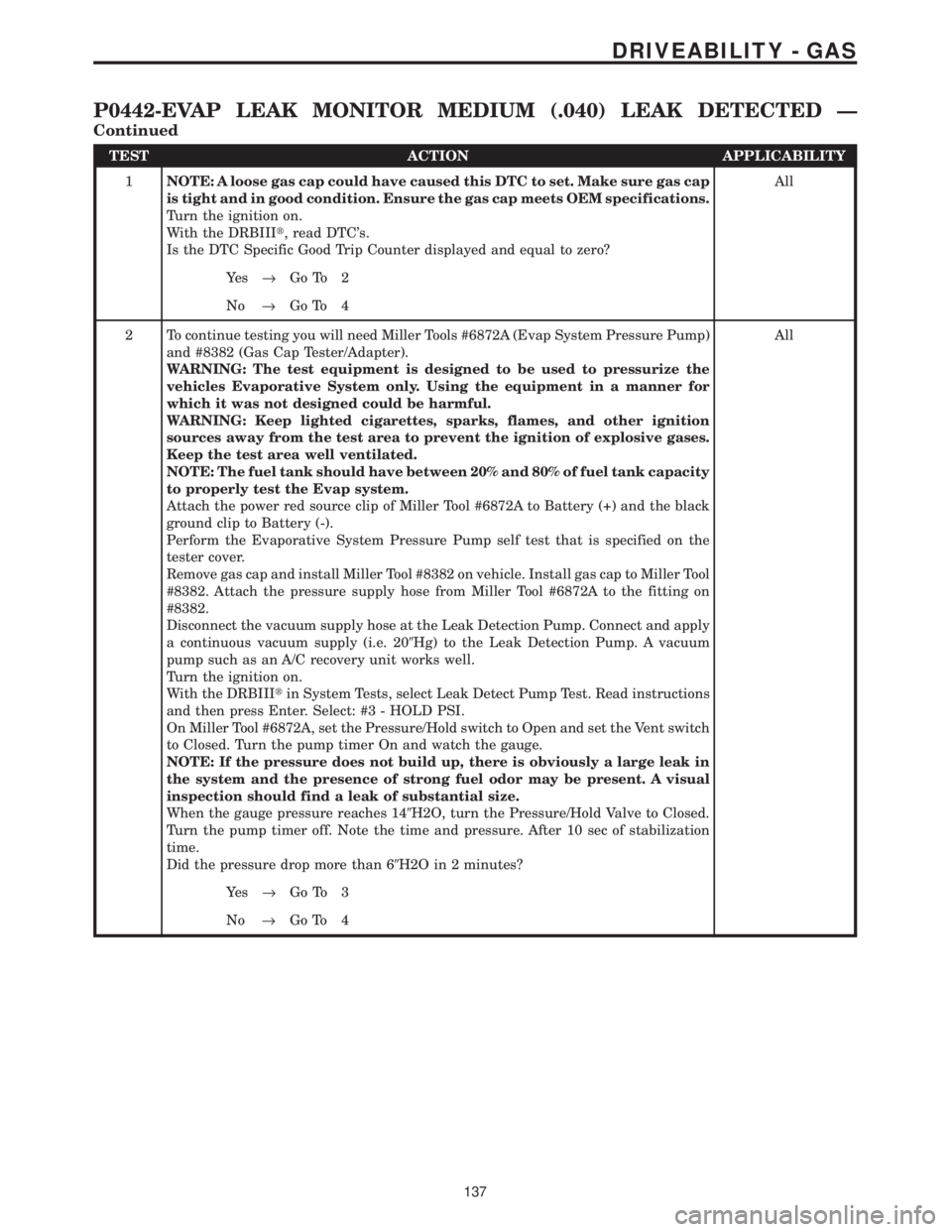
TEST ACTION APPLICABILITY
1NOTE: A loose gas cap could have caused this DTC to set. Make sure gas cap
is tight and in good condition. Ensure the gas cap meets OEM specifications.
Turn the ignition on.
With the DRBIIIt, read DTC's.
Is the DTC Specific Good Trip Counter displayed and equal to zero?All
Ye s®Go To 2
No®Go To 4
2 To continue testing you will need Miller Tools #6872A (Evap System Pressure Pump)
and #8382 (Gas Cap Tester/Adapter).
WARNING: The test equipment is designed to be used to pressurize the
vehicles Evaporative System only. Using the equipment in a manner for
which it was not designed could be harmful.
WARNING: Keep lighted cigarettes, sparks, flames, and other ignition
sources away from the test area to prevent the ignition of explosive gases.
Keep the test area well ventilated.
NOTE: The fuel tank should have between 20% and 80% of fuel tank capacity
to properly test the Evap system.
Attach the power red source clip of Miller Tool #6872A to Battery (+) and the black
ground clip to Battery (-).
Perform the Evaporative System Pressure Pump self test that is specified on the
tester cover.
Remove gas cap and install Miller Tool #8382 on vehicle. Install gas cap to Miller Tool
#8382. Attach the pressure supply hose from Miller Tool #6872A to the fitting on
#8382.
Disconnect the vacuum supply hose at the Leak Detection Pump. Connect and apply
a continuous vacuum supply (i.e. 209Hg) to the Leak Detection Pump. A vacuum
pump such as an A/C recovery unit works well.
Turn the ignition on.
With the DRBIIItin System Tests, select Leak Detect Pump Test. Read instructions
and then press Enter. Select: #3 - HOLD PSI.
On Miller Tool #6872A, set the Pressure/Hold switch to Open and set the Vent switch
to Closed. Turn the pump timer On and watch the gauge.
NOTE: If the pressure does not build up, there is obviously a large leak in
the system and the presence of strong fuel odor may be present. A visual
inspection should find a leak of substantial size.
When the gauge pressure reaches 149H2O, turn the Pressure/Hold Valve to Closed.
Turn the pump timer off. Note the time and pressure. After 10 sec of stabilization
time.
Did the pressure drop more than 69H2O in 2 minutes?All
Ye s®Go To 3
No®Go To 4
137
DRIVEABILITY - GAS
P0442-EVAP LEAK MONITOR MEDIUM (.040) LEAK DETECTED Ð
Continued
Page 3949 of 4284
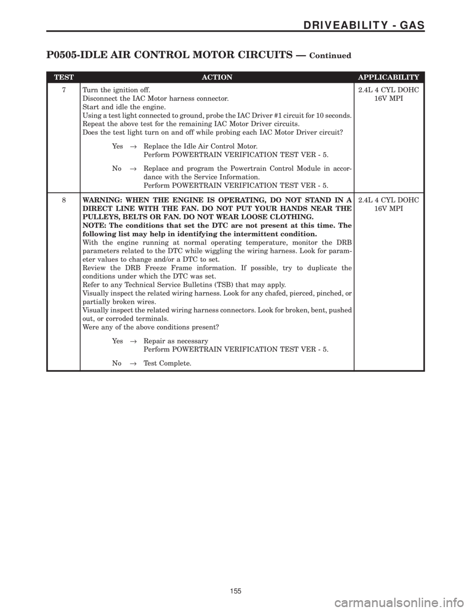
TEST ACTION APPLICABILITY
7 Turn the ignition off.
Disconnect the IAC Motor harness connector.
Start and idle the engine.
Using a test light connected to ground, probe the IAC Driver #1 circuit for 10 seconds.
Repeat the above test for the remaining IAC Motor Driver circuits.
Does the test light turn on and off while probing each IAC Motor Driver circuit?2.4L 4 CYL DOHC
16V MPI
Ye s®Replace the Idle Air Control Motor.
Perform POWERTRAIN VERIFICATION TEST VER - 5.
No®Replace and program the Powertrain Control Module in accor-
dance with the Service Information.
Perform POWERTRAIN VERIFICATION TEST VER - 5.
8WARNING: WHEN THE ENGINE IS OPERATING, DO NOT STAND IN A
DIRECT LINE WITH THE FAN. DO NOT PUT YOUR HANDS NEAR THE
PULLEYS, BELTS OR FAN. DO NOT WEAR LOOSE CLOTHING.
NOTE: The conditions that set the DTC are not present at this time. The
following list may help in identifying the intermittent condition.
With the engine running at normal operating temperature, monitor the DRB
parameters related to the DTC while wiggling the wiring harness. Look for param-
eter values to change and/or a DTC to set.
Review the DRB Freeze Frame information. If possible, try to duplicate the
conditions under which the DTC was set.
Refer to any Technical Service Bulletins (TSB) that may apply.
Visually inspect the related wiring harness. Look for any chafed, pierced, pinched, or
partially broken wires.
Visually inspect the related wiring harness connectors. Look for broken, bent, pushed
out, or corroded terminals.
Were any of the above conditions present?2.4L 4 CYL DOHC
16V MPI
Ye s®Repair as necessary
Perform POWERTRAIN VERIFICATION TEST VER - 5.
No®Test Complete.
155
DRIVEABILITY - GAS
P0505-IDLE AIR CONTROL MOTOR CIRCUITS ÐContinued
Page 3976 of 4284
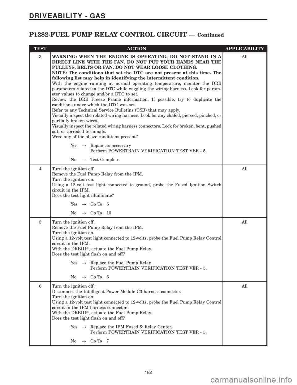
TEST ACTION APPLICABILITY
3WARNING: WHEN THE ENGINE IS OPERATING, DO NOT STAND IN A
DIRECT LINE WITH THE FAN. DO NOT PUT YOUR HANDS NEAR THE
PULLEYS, BELTS OR FAN. DO NOT WEAR LOOSE CLOTHING.
NOTE: The conditions that set the DTC are not present at this time. The
following list may help in identifying the intermittent condition.
With the engine running at normal operating temperature, monitor the DRB
parameters related to the DTC while wiggling the wiring harness. Look for param-
eter values to change and/or a DTC to set.
Review the DRB Freeze Frame information. If possible, try to duplicate the
conditions under which the DTC was set.
Refer to any Technical Service Bulletins (TSB) that may apply.
Visually inspect the related wiring harness. Look for any chafed, pierced, pinched, or
partially broken wires.
Visually inspect the related wiring harness connectors. Look for broken, bent, pushed
out, or corroded terminals.
Were any of the above conditions present?All
Ye s®Repair as necessary
Perform POWERTRAIN VERIFICATION TEST VER - 5.
No®Test Complete.
4 Turn the ignition off.
Remove the Fuel Pump Relay from the IPM.
Turn the ignition on.
Using a 12-volt test light connected to ground, probe the Fused Ignition Switch
circuit in the IPM.
Does the test light illuminate?All
Ye s®Go To 5
No®Go To 10
5 Turn the ignition off.
Remove the Fuel Pump Relay from the IPM.
Turn the ignition on.
Using a 12-volt test light connected to 12-volts, probe the Fuel Pump Relay Control
circuit in the IPM.
With the DRBIIIt, actuate the Fuel Pump Relay.
Does the test light flash on and off?All
Ye s®Replace the Fuel Pump Relay.
Perform POWERTRAIN VERIFICATION TEST VER - 5.
No®Go To 6
6 Turn the ignition off.
Disconnect the Intelligent Power Module C3 harness connector.
Turn the ignition on.
Using a 12-volt test light connected to 12-volts, probe the Fuel Pump Relay Control
circuit in the IPM harness connector..
With the DRBIIIt, actuate the Fuel Pump Relay.
Does the test light flash on and off?All
Ye s®Replace the IPM Fused & Relay Center.
Perform POWERTRAIN VERIFICATION TEST VER - 5.
No®Go To 7
182
DRIVEABILITY - GAS
P1282-FUEL PUMP RELAY CONTROL CIRCUIT ÐContinued
Page 3980 of 4284
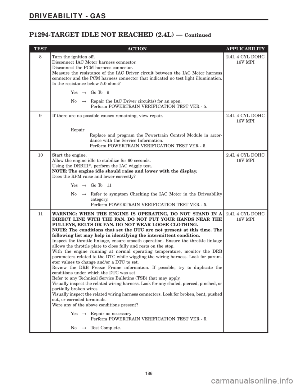
TEST ACTION APPLICABILITY
8 Turn the ignition off.
Disconnect IAC Motor harness connector.
Disconnect the PCM harness connector.
Measure the resistance of the IAC Driver circuit between the IAC Motor harness
connector and the PCM harness connector that indicated no test light illumination.
Is the resistance below 5.0 ohms?2.4L 4 CYL DOHC
16V MPI
Ye s®Go To 9
No®Repair the IAC Driver circuit(s) for an open.
Perform POWERTRAIN VERIFICATION TEST VER - 5.
9 If there are no possible causes remaining, view repair. 2.4L 4 CYL DOHC
16V MPI
Repair
Replace and program the Powertrain Control Module in accor-
dance with the Service Information.
Perform POWERTRAIN VERIFICATION TEST VER - 5.
10 Start the engine.
Allow the engine idle to stabilize for 60 seconds.
Using the DRBIIIt, perform the IAC wiggle test.
NOTE: The engine idle should raise and lower with the display.
Does the RPM raise and lower correctly?2.4L 4 CYL DOHC
16V MPI
Ye s®Go To 11
No®Refer to symptom Checking the IAC Motor in the Driveability
category.
Perform POWERTRAIN VERIFICATION TEST VER - 5.
11WARNING: WHEN THE ENGINE IS OPERATING, DO NOT STAND IN A
DIRECT LINE WITH THE FAN. DO NOT PUT YOUR HANDS NEAR THE
PULLEYS, BELTS OR FAN. DO NOT WEAR LOOSE CLOTHING.
NOTE: The conditions that set the DTC are not present at this time. The
following list may help in identifying the intermittent condition.
Inspect the throttle linkage, ensure smooth operation. Ensure the throttle linkage
allows the throttle plate to close fully and rests on the stop.
With the engine running at normal operating temperature, monitor the DRB
parameters related to the DTC while wiggling the wiring harness. Look for param-
eter values to change and/or a DTC to set.
Review the DRB Freeze Frame information. If possible, try to duplicate the
conditions under which the DTC was set.
Refer to any Technical Service Bulletins (TSB) that may apply.
Visually inspect the related wiring harness. Look for any chafed, pierced, pinched, or
partially broken wires.
Visually inspect the related wiring harness connectors. Look for broken, bent, pushed
out, or corroded terminals.
Were any of the above conditions present?2.4L 4 CYL DOHC
16V MPI
Ye s®Repair as necessary
Perform POWERTRAIN VERIFICATION TEST VER - 5.
No®Test Complete.
186
DRIVEABILITY - GAS
P1294-TARGET IDLE NOT REACHED (2.4L) ÐContinued