2001 CHRYSLER VOYAGER technical data
[x] Cancel search: technical dataPage 1021 of 4284
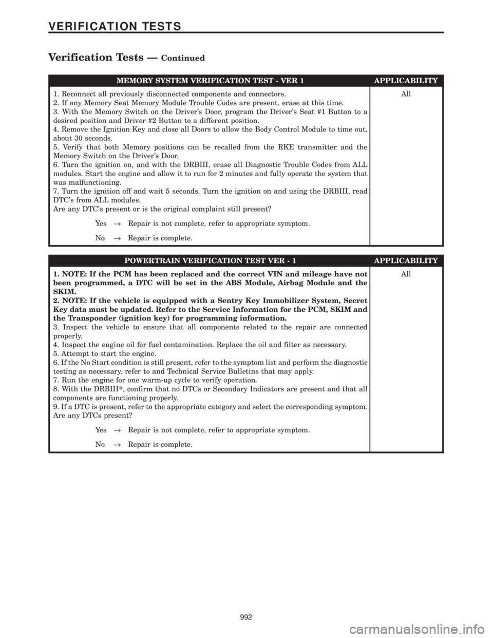
MEMORY SYSTEM VERIFICATION TEST - VER 1 APPLICABILITY
1. Reconnect all previously disconnected components and connectors.
2. If any Memory Seat Memory Module Trouble Codes are present, erase at this time.
3. With the Memory Switch on the Driver's Door, program the Driver's Seat #1 Button to a
desired position and Driver #2 Button to a different position.
4. Remove the Ignition Key and close all Doors to allow the Body Control Module to time out,
about 30 seconds.
5. Verify that both Memory positions can be recalled from the RKE transmitter and the
Memory Switch on the Driver's Door.
6. Turn the ignition on, and with the DRBIII, erase all Diagnostic Trouble Codes from ALL
modules. Start the engine and allow it to run for 2 minutes and fully operate the system that
was malfunctioning.
7. Turn the ignition off and wait 5 seconds. Turn the ignition on and using the DRBIII, read
DTC's from ALL modules.
Are any DTC's present or is the original complaint still present?All
Ye s®Repair is not complete, refer to appropriate symptom.
No®Repair is complete.
POWERTRAIN VERIFICATION TEST VER - 1 APPLICABILITY
1. NOTE: If the PCM has been replaced and the correct VIN and mileage have not
been programmed, a DTC will be set in the ABS Module, Airbag Module and the
SKIM.
2. NOTE: If the vehicle is equipped with a Sentry Key Immobilizer System, Secret
Key data must be updated. Refer to the Service Information for the PCM, SKIM and
the Transponder (ignition key) for programming information.
3. Inspect the vehicle to ensure that all components related to the repair are connected
properly.
4. Inspect the engine oil for fuel contamination. Replace the oil and filter as necessary.
5. Attempt to start the engine.
6. If the No Start condition is still present, refer to the symptom list and perform the diagnostic
testing as necessary. refer to and Technical Service Bulletins that may apply.
7. Run the engine for one warm-up cycle to verify operation.
8. With the DRBIIIt, confirm that no DTCs or Secondary Indicators are present and that all
components are functioning properly.
9. If a DTC is present, refer to the appropriate category and select the corresponding symptom.
Are any DTCs present?All
Ye s®Repair is not complete, refer to appropriate symptom.
No®Repair is complete.
992
VERIFICATION TESTS
Verification Tests ÐContinued
Page 1163 of 4284
4.3 WARNINGS
4.3.1 VEHICLE DAMAGE WARNINGS
Before disconnecting any control module, make
sure the ignition is ``off ''. Failure to do so could
damage the module.
When testing voltage or continuity at any control
module, use the terminal side (not the wire end) of
the connector. Do not probe a wire through the
insulation, this will damage it and eventually cause
it to fail because of corrosion.
Be careful when performing electrical tests so as
to prevent accidental shorting of terminals. Such
mistakes can damage fuses or components. Also, a
second code could be set, making diagnosis of the
original problem more difficult.
4.3.2 ROAD TESTING A COMPLAINT
VEHICLE
Some complaints will require a test drive as part
of the repair verification procedure. The purpose of
the test drive is to try to duplicate the diagnostic
code or symptom condition.
WARNING: BEFORE ROAD TESTING A
VEHICLE, BE SURE THAT ALL
COMPONENTS ARE REASSEMBLED.
DURING THE TEST DRIVE, DO NOT TRY TO
READ THE DRB SCREEN WHILE IN MOTION.
DO NOT HANG THE DRBIIITFROM THE
REAR VIEW MIRROR OR OPERATE IT
YOURSELF. HAVE AN ASSISTANT
AVAILABLE TO OPERATE THE DRBIIIT.
4.4 DIAGNOSIS
1. Your diagnostic test procedure must begin with a
thorough visual inspection of the ABS system for
damaged components or disconnected connec-
tors. The brake lamps must be operational, and
if they are not, repair them prior to continuing.
2. Connect the DRBIIItto the data link connector,
which is located under the dash to the left of the
steering column. If the DRBIIItdoes not power
up, check the power and ground supplies to the
connector.
3. Turn the ignition on. Select ªAntilock Brakesº. If
the DRBIIItdisplays ªNo Responseº condition
you must diagnose that first.
4. Read and record all ABS diagnostic trouble
codes. If the ªCAB Power Feed Circuitº diagnos-
tic trouble code is present, it must be repaired
prior to addressing any other DTC's. If any
additional DTC's are present, proceed to theappropriate test by locating the matching test in
the Table of Contents and begin to diagnose the
symptom.
5. If there are no diagnostic trouble codes present,
identify the customer complaint. Select ªInputs/
Outputsº and read the brake switch input as you
press and release the brake pedal. If the display
does not match the state of the pedal, perform
the proper test by locating the matching test in
the Table of Contents and begin to diagnose the
symptom. If a problem exists with the yellow
ªABSº warning indicator or the red ªBrakeº
indicator exists, refer to the proper tests by
locating the matching test in the Table of Con-
tents and begin to diagnose the symptom. Read
the traction control switch input as you press
and release the switch. If the display does not
match the state of the indicator perform the
proper test by locating the matching test in the
Table of Contents and begin to diagnose the
symptom.
6. If no other problems are found, it will be neces-
sary to road test the vehicle. Perform several
antilock stops from above 50 Km/h (30 mph) and
then repeat step 4. If any diagnostic trouble
codes are present, proceed to the appropriate test.
7. The following conditions should be considered
ªNORMALº operation, and no repairs should be
attempted to correct them.
± Brake pedal feedback during an ABS stop
(clicking, vibrating).
± Clicking, groaning or buzzing at 25 Km/h (15
mph) or 40 Km/h (24 mph) (drive off self test).
± Groaning noise during an ABS stop.
± Slight brake pedal drop and pop noise when
ignition is initially turned on.
± Brake pedal ratcheting down at the end of an
ABS stop.
8. If the complaint is ABS ªcyclingº at the end of a
stop at low speeds, it may be caused by a
marginal wheel speed sensor signal. The sensor
air gap, tone wheel condition, and/or brakes
hanging up are possible causes of this condition.
9. After a road test in which no problems were
found, refer to any Technical Service Bulletins
that may apply.
5.0 REQUIRED TOOLS AND
EQUIPMENT
DRBIIIt(diagnostic read-out box)
jumper wires
ohmmeter
voltmeter
test light
6
GENERAL INFORMATION
Page 1848 of 4284
Control Module. The sliding door control module con-
tains software technology which enables it to detect
resistance to door travel and to reverse door travel in
order to avoid damage to the door or to avoid possible
personal injury if the obstruction is a person. This
feature functions in both the opening and closing
cycles. If the power sliding door system develops any
problems the control module will store and recall
Diagnostic Trouble Codes (DTC). The use of a diag-
nostic scan tool, such as the DRB IIItis required to
read and troubleshoot these trouble codes. The slid-
ing door control module can be reflashed if necessary.
Refer to the latest Technical Service Bulletin (TSB)
Information for any updates.
The power door control module is a replaceable
component and cannot be repaired, if found to be
faulty it must be replaced. Consult your Mopary
parts catalog for a specific part number.
OPERATION
The power sliding door control module serves as
the main computer for the power sliding side door
system. All power door functions are processed
through the power door control module and/or the
vehicles body control module (BCM). At the start of a
power open command, a signal is sent to the BCM
and then to the power door control module via the
J1850 data bus circuit. This signal, generated by any
of the power door command switches, tells the power
door control module to activate a power latch release,
engage the clutch assembly and drive the door into
the full open position. If an obstacle is felt during
this power open cycle, the module will reverse direc-
tion and close the door. This process is also enabled
during a power close cycle. This process will repeat
three times, and if a fourth obstacle is detected, the
door will go into full manual mode. Once the full
open position is obtained, a hold open latch assembly
mounted full open switch tells the control module
that the door has reached the full open position. If
the power sliding door system develops any problems
the control module will store and recall Diagnostic
Trouble Codes (DTC). The use of a diagnostic scan
tool, such as the DRB IIItis required to read and
troubleshoot these trouble codes.
REMOVAL
(1) Disconnect and isolate the negative battery
cable.
(2) Remove the appropriate door trim panel from
the vehicle. Refer to Body for the procedure.
(3) Remove the weather shield. Refer to Body for
the procedure.
(4) Disconnect the power door control module elec-
trical connectors. Slide the red locking tab out (awayfrom module) and depress connector retaining tab,
while pulling straight apart.
(5) Remove the control module retaining screw.
(6) Remove the module from the vehicle.
INSTALLATION
(1) Position the control module and install the
retaining screw.
(2) Connect the control module electrical connec-
tors. Slide the locking tab into the locked position.
(3) Install the appropriate door trim panel on the
vehicle. Refer to Body for the procedure.
(4) Install the weather shield. Refer to Body for
the procedure.
(5) Connect the negative battery cable.
(6) Using an appropriate scan tool, check and
erase any power door control module diagnostic trou-
ble codes.
(7) Verify power door system operation. Cycle the
power door through one complete open and close
cycle.
TRANSMISSION CONTROL
MODULE
DESCRIPTION
The Transmission Control Module (TCM) is located
behind the left fender and is fastened with three
screws to three clips in the left frame rail forward of
the suspension (Fig. 13).
OPERATION
The TCM is the controlling unit for all electronic
operations of the transaxle. The TCM receives infor-
mation regarding vehicle operation from both direct
and indirect inputs, and selects the operational mode
of the transaxle. Direct inputs are hardwired to, and
used specifically by the TCM. Indirect inputs origi-
nate from other components/modules, and are shared
with the TCM via the communication bus.
Some examples ofdirect inputsto the TCM are:
²Battery (B+) voltage
²Ignition ªONº voltage
²Transmission Control Relay (Switched B+)
²Throttle Position Sensor
²Crankshaft Position Sensor (CKP)
²Transmission Range Sensor (TRS)
²Pressure Switches (L/R, 2/4, OD)
²Transmission Temperature Sensor (Integral to
TRS)
²Input Shaft Speed Sensor
8E - 24 ELECTRONIC CONTROL MODULESRS
SLIDING DOOR CONTROL MODULE (Continued)
Page 3802 of 4284
powertrain control module checks that circuit or
function. Procedures in this manual verify if the
DTC is a hard code at the beginning of each test.
When it is not a hard code, an intermittent test
must be performed.
DTC's that are for Euro Stage III OBD monitors
will not set with just the ignition key on. Comparing
these to non-emission DTC's, they will seem like an
intermittent. These DTC's require a set of parame-
ters to be performed (The DRBIIItpre-test screens
will help with this for MONITOR DTC's), this is
called a TRIP. All Euro Stage III OBD DTCs will be
set after one or in some cases two trip failures, and
the MIL will be turned on. These DTC's require
three successful, no failures, TRIPS to extinguish
the MIL, followed by 40 warm-up cycles to erase the
DTC.
3.3.2 INTERMITTENT CODE
A diagnostic trouble code that is not there every
time the PCM checks the circuit is an intermittent
DTC. Most intermittent DTC's are caused by wiring
or connector problems. Defects that come and go
like this are the most difficult to diagnose; they
must be looked for under specific conditions that
cause them. The following checks may assist you in
identifying a possible intermittent problem:
²Visually inspect related wire harness connectors.
Look for broken, bent, pushed out, or corroded
terminals.
²Visually inspect the related harnesses. Look for
chafed, pierced, or partially broken wire.
²Refer to any technical service bulletins that may
apply.
²Use the DRBIIItdata recorder or co-pilot.
3.3.3 DISTANCE SINCE MI SET
The Euro Stage III OBD directive requires that
the distance traveled by the vehicle while theMIis
activated must be available at any instant through
the serial port on the standard data link connector.
This feature works as follows:1. If the MI is illuminated due to a fault, the
distance count is updated (i.e. it is counting).
2. If there is a9stale9MI fault (i.e. the fault is still
frozen in memory but the MI has heen extin-
guished due to 3 good trips), the distance count is
held (i.e. frozen).
3. If the distance count is being held due to (Item
2.) and the fault is cleared, the distance is
cleared (set to zero).
4. If the distance count is being held due to (Item
2.) and another MI occurs, the distance count is
reset (to 0) and begins updating anew.
5. If a fault occurs while the MI is already illumi-
nated due to a previous fault (the distance count
is updating), then the distance count continues
to update w/out interruption.
6. If the MI is flashing due to activate misfire and
there is and9active9fault (i.e. matured fault for
which 3 good trips have not occurred), the dis-
tance count behaves as the MI in ON.
7. If the MI is flashing due to active misfire and
there is no9active9fault (i.e. the MI is flashing
for a 1 malf.), the distance count behaves as if
the MI is off (because it is not yet a matured
fault).
8. The distance count is cleared whenever the fault
is cleared. (Via 40 warm up cycles, or via scan
tool).
3.3.4 HANDLING NO DTC PROBLEMS
Symptom checks cannot be used properly unless
the driveability problem characteristic actually
happens while the vehicle is being tested.
Select the symptom that most accurately de-
scribes the vehicle's driveability problem and then
perform the test routine that pertains to this symp-
tom. Perform each routine test in sequence until the
problem is found. For definitions, see Section 6.0
Glossary Of Terms.
SYMPTOM DIAGNOSTIC TEST
HARD START CHECKING THE FUEL PRESSURE
CHECKING THE ECT SENSOR
CHECKING THROTTLE POSITION SENSOR
CHECKING MAP SENSOR
CHECKING IDLE AIR CONTROL MOTOR OPERATION
CHECKING EGR SYSTEM
CHECKING IAT SENSOR
8
GENERAL INFORMATION
Page 3932 of 4284
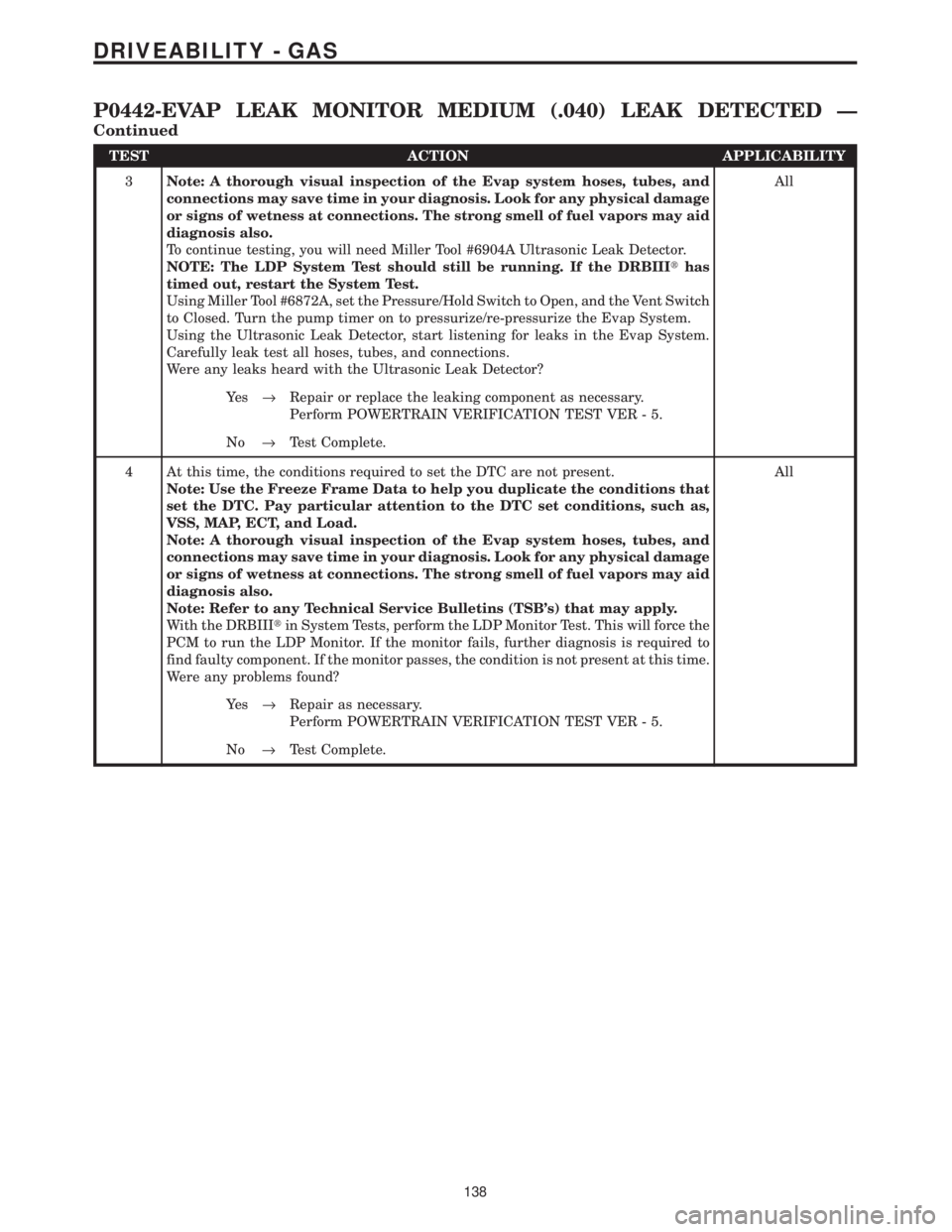
TEST ACTION APPLICABILITY
3Note: A thorough visual inspection of the Evap system hoses, tubes, and
connections may save time in your diagnosis. Look for any physical damage
or signs of wetness at connections. The strong smell of fuel vapors may aid
diagnosis also.
To continue testing, you will need Miller Tool #6904A Ultrasonic Leak Detector.
NOTE: The LDP System Test should still be running. If the DRBIIIthas
timed out, restart the System Test.
Using Miller Tool #6872A, set the Pressure/Hold Switch to Open, and the Vent Switch
to Closed. Turn the pump timer on to pressurize/re-pressurize the Evap System.
Using the Ultrasonic Leak Detector, start listening for leaks in the Evap System.
Carefully leak test all hoses, tubes, and connections.
Were any leaks heard with the Ultrasonic Leak Detector?All
Ye s®Repair or replace the leaking component as necessary.
Perform POWERTRAIN VERIFICATION TEST VER - 5.
No®Test Complete.
4 At this time, the conditions required to set the DTC are not present.
Note: Use the Freeze Frame Data to help you duplicate the conditions that
set the DTC. Pay particular attention to the DTC set conditions, such as,
VSS, MAP, ECT, and Load.
Note: A thorough visual inspection of the Evap system hoses, tubes, and
connections may save time in your diagnosis. Look for any physical damage
or signs of wetness at connections. The strong smell of fuel vapors may aid
diagnosis also.
Note: Refer to any Technical Service Bulletins (TSB's) that may apply.
With the DRBIIItin System Tests, perform the LDP Monitor Test. This will force the
PCM to run the LDP Monitor. If the monitor fails, further diagnosis is required to
find faulty component. If the monitor passes, the condition is not present at this time.
Were any problems found?All
Ye s®Repair as necessary.
Perform POWERTRAIN VERIFICATION TEST VER - 5.
No®Test Complete.
138
DRIVEABILITY - GAS
P0442-EVAP LEAK MONITOR MEDIUM (.040) LEAK DETECTED Ð
Continued
Page 4003 of 4284
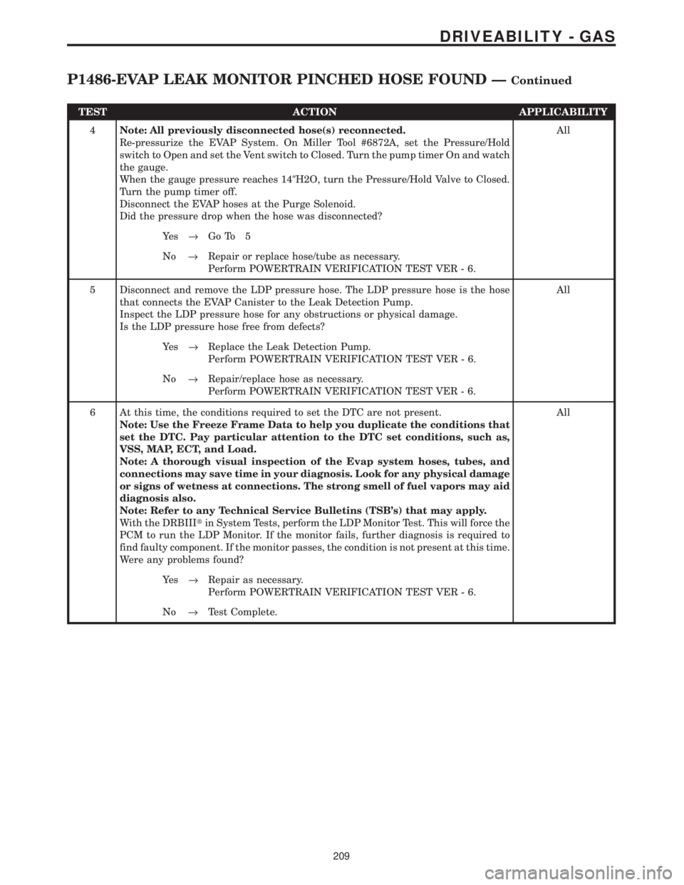
TEST ACTION APPLICABILITY
4Note: All previously disconnected hose(s) reconnected.
Re-pressurize the EVAP System. On Miller Tool #6872A, set the Pressure/Hold
switch to Open and set the Vent switch to Closed. Turn the pump timer On and watch
the gauge.
When the gauge pressure reaches 149H2O, turn the Pressure/Hold Valve to Closed.
Turn the pump timer off.
Disconnect the EVAP hoses at the Purge Solenoid.
Did the pressure drop when the hose was disconnected?All
Ye s®Go To 5
No®Repair or replace hose/tube as necessary.
Perform POWERTRAIN VERIFICATION TEST VER - 6.
5 Disconnect and remove the LDP pressure hose. The LDP pressure hose is the hose
that connects the EVAP Canister to the Leak Detection Pump.
Inspect the LDP pressure hose for any obstructions or physical damage.
Is the LDP pressure hose free from defects?All
Ye s®Replace the Leak Detection Pump.
Perform POWERTRAIN VERIFICATION TEST VER - 6.
No®Repair/replace hose as necessary.
Perform POWERTRAIN VERIFICATION TEST VER - 6.
6 At this time, the conditions required to set the DTC are not present.
Note: Use the Freeze Frame Data to help you duplicate the conditions that
set the DTC. Pay particular attention to the DTC set conditions, such as,
VSS, MAP, ECT, and Load.
Note: A thorough visual inspection of the Evap system hoses, tubes, and
connections may save time in your diagnosis. Look for any physical damage
or signs of wetness at connections. The strong smell of fuel vapors may aid
diagnosis also.
Note: Refer to any Technical Service Bulletins (TSB's) that may apply.
With the DRBIIItin System Tests, perform the LDP Monitor Test. This will force the
PCM to run the LDP Monitor. If the monitor fails, further diagnosis is required to
find faulty component. If the monitor passes, the condition is not present at this time.
Were any problems found?All
Ye s®Repair as necessary.
Perform POWERTRAIN VERIFICATION TEST VER - 6.
No®Test Complete.
209
DRIVEABILITY - GAS
P1486-EVAP LEAK MONITOR PINCHED HOSE FOUND ÐContinued
Page 4009 of 4284
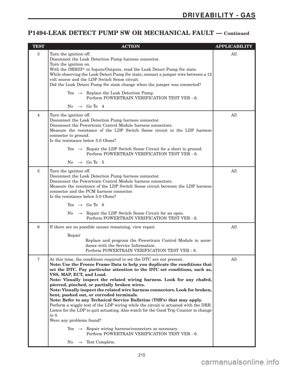
TEST ACTION APPLICABILITY
3 Turn the ignition off.
Disconnect the Leak Detection Pump harness connector.
Turn the ignition on.
With the DRBIIItin Inputs/Outputs, read the Leak Detect Pump Sw state.
While observing the Leak Detect Pump Sw state, connect a jumper wire between a 12
volt source and the LDP Switch Sense circuit.
Did the Leak Detect Pump Sw state change when the jumper was connected?All
Ye s®Replace the Leak Detection Pump.
Perform POWERTRAIN VERIFICATION TEST VER - 6.
No®Go To 4
4 Turn the ignition off.
Disconnect the Leak Detection Pump harness connector.
Disconnect the Powertrain Control Module harness connectors.
Measure the resistance of the LDP Switch Sense circuit in the LDP harness
connector to ground.
Is the resistance below 5.0 Ohms?All
Ye s®Repair the LDP Switch Sense Circuit for a short to ground.
Perform POWERTRAIN VERIFICATION TEST VER - 6.
No®Go To 5
5 Turn the ignition off.
Disconnect the Leak Detection Pump harness connector.
Disconnect the Powertrain Control Module harness connectors.
Measure the resistance of the LDP Switch Sense circuit between the LDP harness
connector and the PCM harness connector.
Is the resistance below 5.0 Ohms?All
Ye s®Go To 6
No®Repair the LDP Switch Sense Circuit for an open.
Perform POWERTRAIN VERIFICATION TEST VER - 6.
6 If there are no possible causes remaining, view repair. All
Repair
Replace and program the Powertrain Control Module in accor-
dance with the Service Information.
Perform POWERTRAIN VERIFICATION TEST VER - 6.
7 At this time, the conditions required to set the DTC are not present.
Note: Use the Freeze Frame Data to help you duplicate the conditions that
set the DTC. Pay particular attention to the DTC set conditions, such as,
VSS, MAP, ECT, and Load.
Note: Visually inspect the related wiring harness. Look for any chafed,
pierced, pinched, or partially broken wires.
Note: Visually inspect the related wire harness connectors. Look for broken,
bent, pushed out, or corroded terminals.
Note: Refer to any Technical Service Bulletins (TSB's) that may apply.
Perform a wiggle test of the LDP wiring while the circuit is actuated with the DRB.
Listen for the LDP to quit actuating. Also watch for the Good Trip Counter to change
to 0.
Were any problems found?All
Ye s®Repair wiring harness/connectors as necessary.
Perform POWERTRAIN VERIFICATION TEST VER - 6.
No®Test Complete.
215
DRIVEABILITY - GAS
P1494-LEAK DETECT PUMP SW OR MECHANICAL FAULT ÐContinued
Page 4011 of 4284
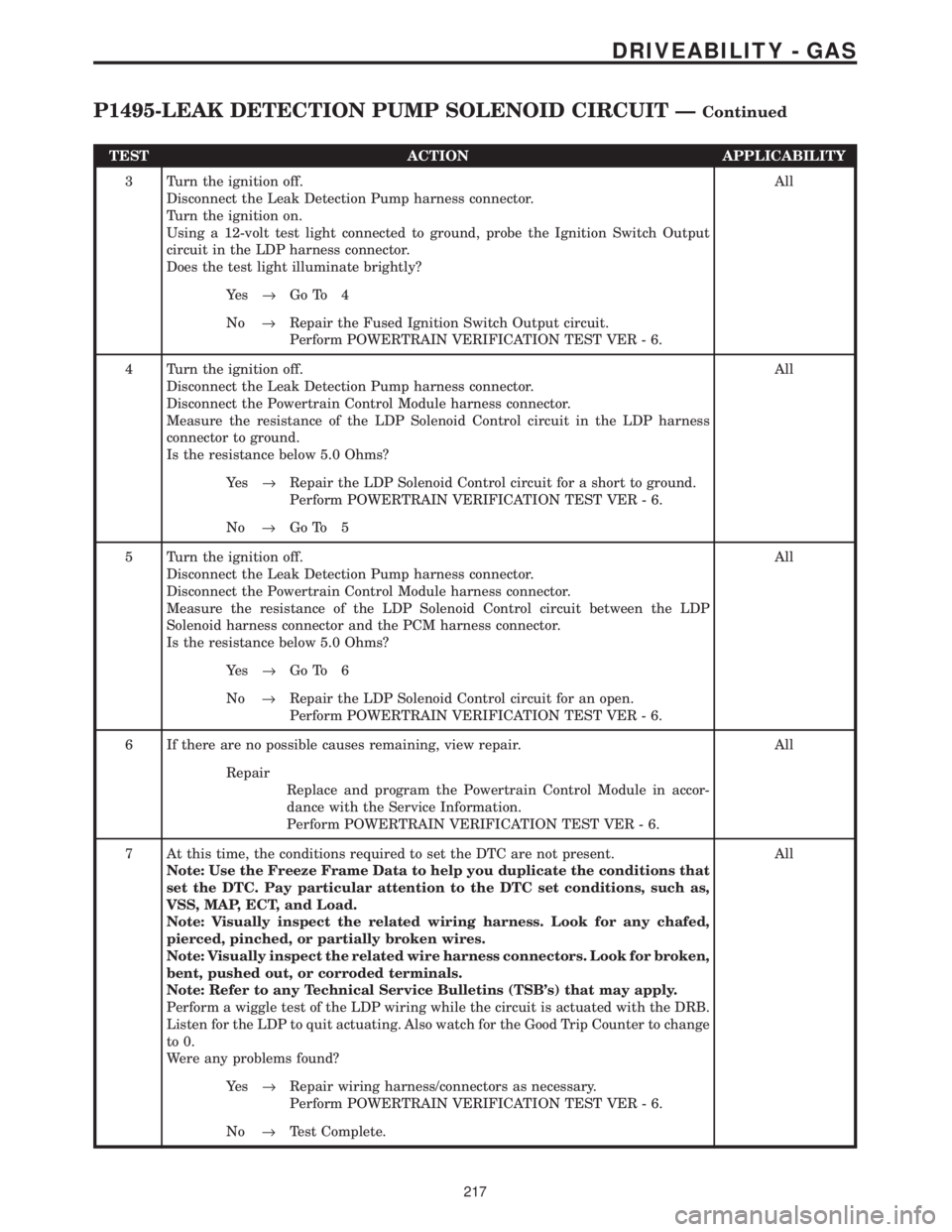
TEST ACTION APPLICABILITY
3 Turn the ignition off.
Disconnect the Leak Detection Pump harness connector.
Turn the ignition on.
Using a 12-volt test light connected to ground, probe the Ignition Switch Output
circuit in the LDP harness connector.
Does the test light illuminate brightly?All
Ye s®Go To 4
No®Repair the Fused Ignition Switch Output circuit.
Perform POWERTRAIN VERIFICATION TEST VER - 6.
4 Turn the ignition off.
Disconnect the Leak Detection Pump harness connector.
Disconnect the Powertrain Control Module harness connector.
Measure the resistance of the LDP Solenoid Control circuit in the LDP harness
connector to ground.
Is the resistance below 5.0 Ohms?All
Ye s®Repair the LDP Solenoid Control circuit for a short to ground.
Perform POWERTRAIN VERIFICATION TEST VER - 6.
No®Go To 5
5 Turn the ignition off.
Disconnect the Leak Detection Pump harness connector.
Disconnect the Powertrain Control Module harness connector.
Measure the resistance of the LDP Solenoid Control circuit between the LDP
Solenoid harness connector and the PCM harness connector.
Is the resistance below 5.0 Ohms?All
Ye s®Go To 6
No®Repair the LDP Solenoid Control circuit for an open.
Perform POWERTRAIN VERIFICATION TEST VER - 6.
6 If there are no possible causes remaining, view repair. All
Repair
Replace and program the Powertrain Control Module in accor-
dance with the Service Information.
Perform POWERTRAIN VERIFICATION TEST VER - 6.
7 At this time, the conditions required to set the DTC are not present.
Note: Use the Freeze Frame Data to help you duplicate the conditions that
set the DTC. Pay particular attention to the DTC set conditions, such as,
VSS, MAP, ECT, and Load.
Note: Visually inspect the related wiring harness. Look for any chafed,
pierced, pinched, or partially broken wires.
Note: Visually inspect the related wire harness connectors. Look for broken,
bent, pushed out, or corroded terminals.
Note: Refer to any Technical Service Bulletins (TSB's) that may apply.
Perform a wiggle test of the LDP wiring while the circuit is actuated with the DRB.
Listen for the LDP to quit actuating. Also watch for the Good Trip Counter to change
to 0.
Were any problems found?All
Ye s®Repair wiring harness/connectors as necessary.
Perform POWERTRAIN VERIFICATION TEST VER - 6.
No®Test Complete.
217
DRIVEABILITY - GAS
P1495-LEAK DETECTION PUMP SOLENOID CIRCUIT ÐContinued