2001 CHRYSLER VOYAGER frame
[x] Cancel search: framePage 1560 of 4284
STABILIZER BAR
DESCRIPTION
(1) Front-wheel-drive models use a stabilizer bar
that is mounted behind the rear axle. All-wheel-drive
models use a stabilizer bar that is mounted in front
of the rear axle.
The stabilizer bar interconnects both sides of the
rear axle and attaches to the rear frame rails using 2
rubber isolated link arms.
Both type stabilizer bars have the same basic com-
ponents. Attachment to the rear axle tube, and rear
frame rails is through rubber-isolated bushings.
The 2 rubber isolated links are connected to the
rear frame rails by brackets. These brackets are
bolted to the bottom of the frame rails.
OPERATION
Jounce and rebound movements affecting one
wheel are partially transmitted to the opposite wheel
to reduce body roll.
REMOVAL - AWD
(1) Raise vehicle. See Hoisting in Lubrication and
Maintenance.
(2) Remove the bolts securing the stabilizer bar to
links on each end of the bar.
(3) While holding the stabilizer bar in place,
remove the bolts that attach the stabilizer bar bush-
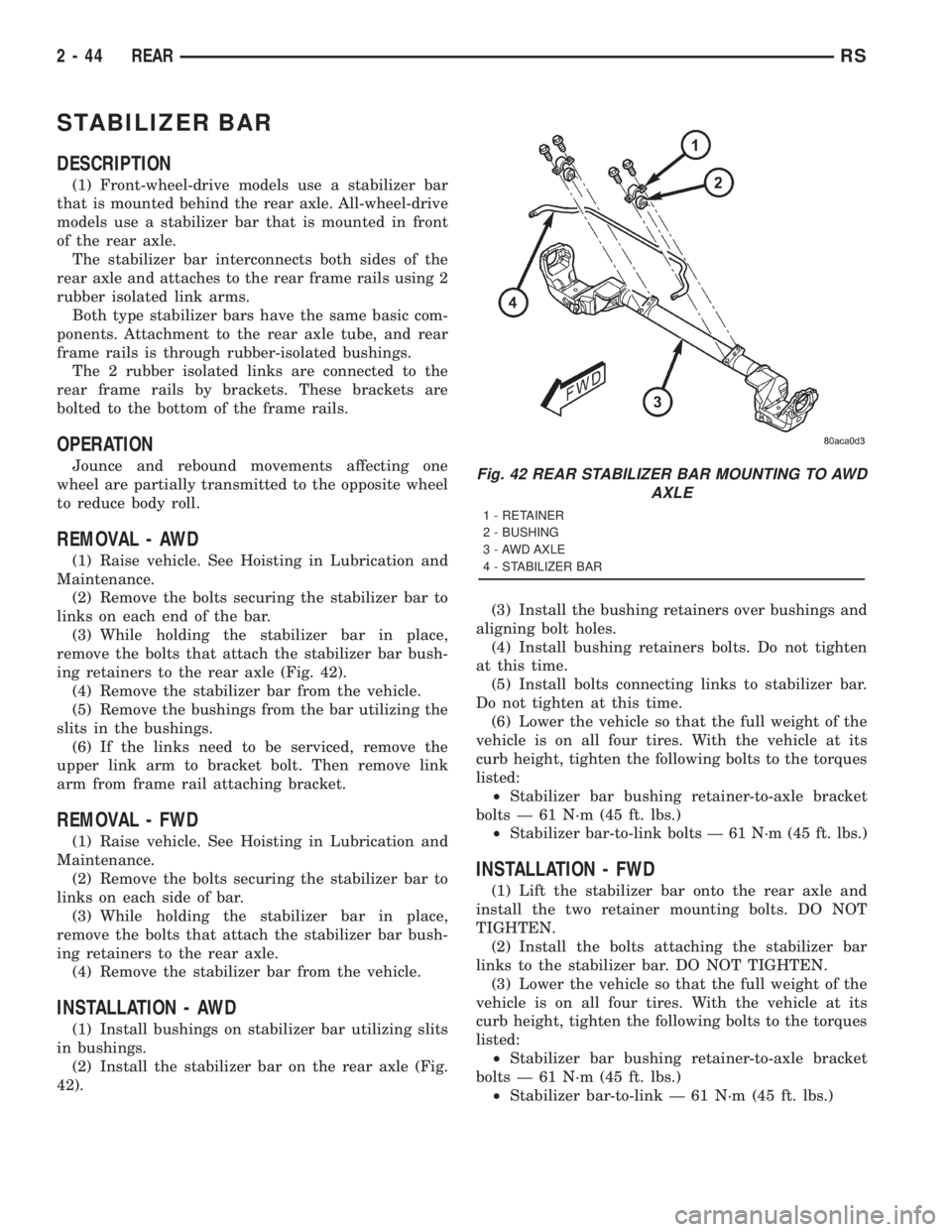
ing retainers to the rear axle (Fig. 42).
(4) Remove the stabilizer bar from the vehicle.
(5) Remove the bushings from the bar utilizing the
slits in the bushings.
(6) If the links need to be serviced, remove the
upper link arm to bracket bolt. Then remove link
arm from frame rail attaching bracket.
REMOVAL - FWD
(1) Raise vehicle. See Hoisting in Lubrication and
Maintenance.
(2) Remove the bolts securing the stabilizer bar to
links on each side of bar.
(3) While holding the stabilizer bar in place,
remove the bolts that attach the stabilizer bar bush-
ing retainers to the rear axle.
(4) Remove the stabilizer bar from the vehicle.
INSTALLATION - AWD
(1) Install bushings on stabilizer bar utilizing slits
in bushings.
(2) Install the stabilizer bar on the rear axle (Fig.
42).(3) Install the bushing retainers over bushings and
aligning bolt holes.
(4) Install bushing retainers bolts. Do not tighten
at this time.
(5) Install bolts connecting links to stabilizer bar.
Do not tighten at this time.
(6) Lower the vehicle so that the full weight of the
vehicle is on all four tires. With the vehicle at its
curb height, tighten the following bolts to the torques
listed:
²Stabilizer bar bushing retainer-to-axle bracket
bolts Ð 61 N´m (45 ft. lbs.)
²Stabilizer bar-to-link bolts Ð 61 N´m (45 ft. lbs.)
INSTALLATION - FWD
(1) Lift the stabilizer bar onto the rear axle and
install the two retainer mounting bolts. DO NOT
TIGHTEN.
(2) Install the bolts attaching the stabilizer bar
links to the stabilizer bar. DO NOT TIGHTEN.
(3) Lower the vehicle so that the full weight of the
vehicle is on all four tires. With the vehicle at its
curb height, tighten the following bolts to the torques
listed:
²Stabilizer bar bushing retainer-to-axle bracket
bolts Ð 61 N´m (45 ft. lbs.)
²Stabilizer bar-to-link Ð 61 N´m (45 ft. lbs.)
Fig. 42 REAR STABILIZER BAR MOUNTING TO AWD
AXLE
1 - RETAINER
2 - BUSHING
3 - AWD AXLE
4 - STABILIZER BAR
2 - 44 REARRS
Page 1561 of 4284
TRACK BAR
DESCRIPTION
On front-wheel-drive applications of this vehicle
that are equipped with single leaf rear springs, a
track bar is used on the rear axle (Fig. 1).
The track bar connects the rear axle to the frame/
body of the vehicle. The track bar is isolated from the
body of the vehicle by an isolator bushing located in
each end of the track bar.
OPERATION
The track bar prevents excessive side-to-side move-
ment of the rear axle. The track bar is used to keep
the location of the axle in the correct position for
optimum handling and control of the vehicle.
REMOVAL
(1) Remove the nut and bolt mounting the track
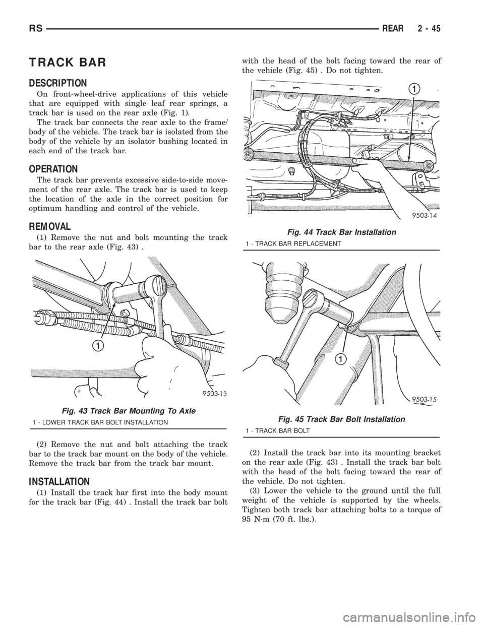
bar to the rear axle (Fig. 43) .
(2) Remove the nut and bolt attaching the track
bar to the track bar mount on the body of the vehicle.
Remove the track bar from the track bar mount.
INSTALLATION
(1) Install the track bar first into the body mount
for the track bar (Fig. 44) . Install the track bar boltwith the head of the bolt facing toward the rear of
the vehicle (Fig. 45) . Do not tighten.
(2) Install the track bar into its mounting bracket
on the rear axle (Fig. 43) . Install the track bar bolt
with the head of the bolt facing toward the rear of
the vehicle. Do not tighten.
(3) Lower the vehicle to the ground until the full
weight of the vehicle is supported by the wheels.
Tighten both track bar attaching bolts to a torque of
95 N´m (70 ft. lbs.).
Fig. 43 Track Bar Mounting To Axle
1 - LOWER TRACK BAR BOLT INSTALLATION
Fig. 44 Track Bar Installation
1 - TRACK BAR REPLACEMENT
Fig. 45 Track Bar Bolt Installation
1 - TRACK BAR BOLT
RSREAR2-45
Page 1564 of 4284
and undue tire wear when steering a vehicle through
a turn.
DYNAMIC TOE PATTERN
Dynamic toe pattern is the inward and outward toe
movement of the front and rear tires through the
suspension's jounce and rebound travel. As the vehi-
cle's suspension moves up and down, the toe pattern
varies. Toe pattern is critical in controlling the direc-
tional stability of the vehicle while in motion. Front
and rear dynamic toe pattern is preset by the factory
at the time the vehicle is assembled.
It is not necessary to check or adjust front or rear
dynamic toe pattern when doing a normal wheel
alignment. The only time dynamic toe pattern needs
to be checked or adjusted is if the frame of the vehi-
cle has been damaged.
STEERING AXIS INCLINATION (S. A. I.)
Steering axis inclination is the angle between a
true vertical line starting at the center of the tire at
the road contact point and a line drawn through the
center of the upper ball joint (or strut) and the lower
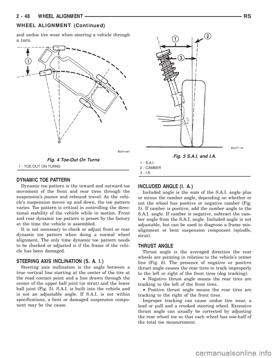
ball joint (Fig. 5). S.A.I. is built into the vehicle and
is not an adjustable angle. If S.A.I. is not within
specifications, a bent or damaged suspension compo-
nent may be the cause.
INCLUDED ANGLE (I. A.)
Included angle is the sum of the S.A.I. angle plus
or minus the camber angle, depending on whether or
not the wheel has positive or negative camber (Fig.
5). If camber is positive, add the camber angle to the
S.A.I. angle. If camber is negative, subtract the cam-
ber angle from the S.A.I. angle. Included angle is not
adjustable, but can be used to diagnose a frame mis-
alignment or bent suspension component (spindle,
strut).
THRUST ANGLE
Thrust angle is the averaged direction the rear
wheels are pointing in relation to the vehicle's center
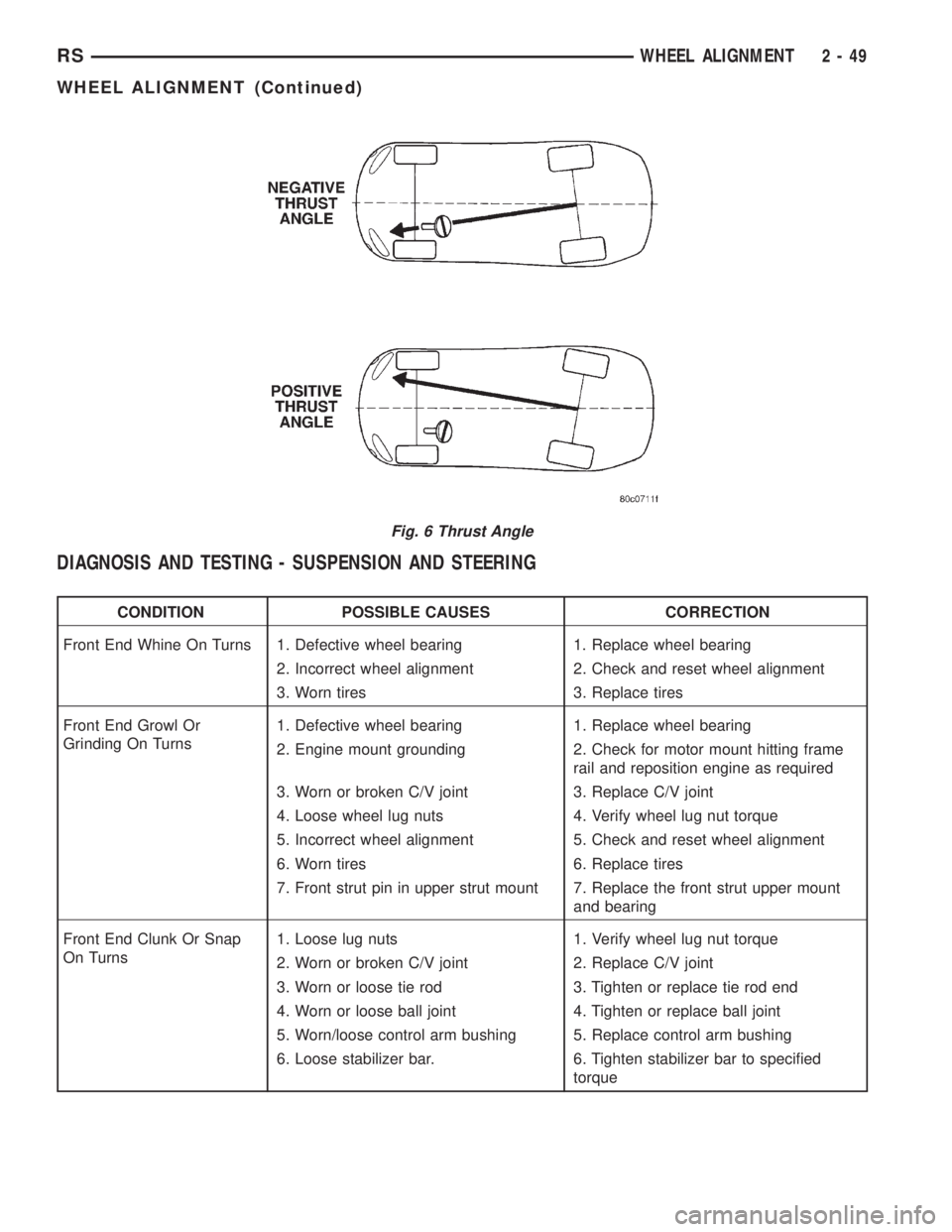
line (Fig. 6). The presence of negative or positive
thrust angle causes the rear tires to track improperly
to the left or right of the front tires (dog tracking).
²Negative thrust angle means the rear tires are
tracking to the left of the front tires.
²Positive thrust angle means the rear tires are
tracking to the right of the front tires.
Improper tracking can cause undue tire wear, a
lead or pull and a crooked steering wheel. Excessive
thrust angle can usually be corrected by adjusting
the rear wheel toe so that each wheel has one-half of
the total toe measurement.
Fig. 4 Toe-Out On Turns
1 - TOE-OUT ON TURNS
Fig. 5 S.A.I. and I.A.
1 - S.A.I.
2 - CAMBER
3 - I.A.
2 - 48 WHEEL ALIGNMENTRS
WHEEL ALIGNMENT (Continued)
Page 1565 of 4284
DIAGNOSIS AND TESTING - SUSPENSION AND STEERING
CONDITION POSSIBLE CAUSES CORRECTION
Front End Whine On Turns 1. Defective wheel bearing 1. Replace wheel bearing
2. Incorrect wheel alignment 2. Check and reset wheel alignment
3. Worn tires 3. Replace tires
Front End Growl Or
Grinding On Turns1. Defective wheel bearing 1. Replace wheel bearing
2. Engine mount grounding 2. Check for motor mount hitting frame
rail and reposition engine as required
3. Worn or broken C/V joint 3. Replace C/V joint
4. Loose wheel lug nuts 4. Verify wheel lug nut torque
5. Incorrect wheel alignment 5. Check and reset wheel alignment
6. Worn tires 6. Replace tires
7. Front strut pin in upper strut mount 7. Replace the front strut upper mount
and bearing
Front End Clunk Or Snap
On Turns1. Loose lug nuts 1. Verify wheel lug nut torque
2. Worn or broken C/V joint 2. Replace C/V joint
3. Worn or loose tie rod 3. Tighten or replace tie rod end
4. Worn or loose ball joint 4. Tighten or replace ball joint
5. Worn/loose control arm bushing 5. Replace control arm bushing
6. Loose stabilizer bar. 6. Tighten stabilizer bar to specified
torque
Fig. 6 Thrust Angle
RSWHEEL ALIGNMENT2-49
WHEEL ALIGNMENT (Continued)
Page 1578 of 4284
²Noise may also be caused by another component
of the vehicle coming in contact with the half shafts.
CLUNKING NOISE DURING ACCELERATION
This noise may be a result of one of the following
conditions:
²A torn seal boot on the inner or outer joint of the
half shaft assembly.
²A loose or missing clamp on the inner or outer
joint of the half shaft assembly.
²A damaged or worn half shaft CV joint.
SHUDDER OR VIBRATION DURING ACCELERATION
This problem could be a result of:
²A worn or damaged half shaft inner tripod joint.
²A sticking tripod joint spider assembly (inner tri-
pod joint only).
²Improper wheel alignment. (Refer to 2 - SUS-
PENSION/WHEEL ALIGNMENT - STANDARD
PROCEDURE)
VIBRATION AT HIGHWAY SPEEDS
This problem could be a result of:
²Foreign material (mud, etc.) packed on the back-
side of the wheel(s).
²Out of balance tires or wheels. (Refer to 22 -
TIRES/WHEELS - STANDARD PROCEDURE)
²Improper tire and/or wheel runout. (Refer to 22 -
TIRES/WHEELS - DIAGNOSIS AND TESTING)
REMOVAL
(1) Raise vehicle on jack stands or centered on a
frame contact type hoist.
(2) Remove the cotter pin and nut lock (Fig. 2)
from the end of the half shaft.
(3) Remove the wave washer (Fig. 3) from the end
of the half shaft.
(4) Remove the wheel and tire assembly from the
vehicle. (Refer to 22 - TIRES/WHEELS - REMOVAL)
(5) With the vehicle's brakes applied to keep hub
from turning,loosen and removethe half shaft
nut.
(6) Remove the two front disc brake caliper
adapter to steering knuckle attaching bolts (Fig. 4).
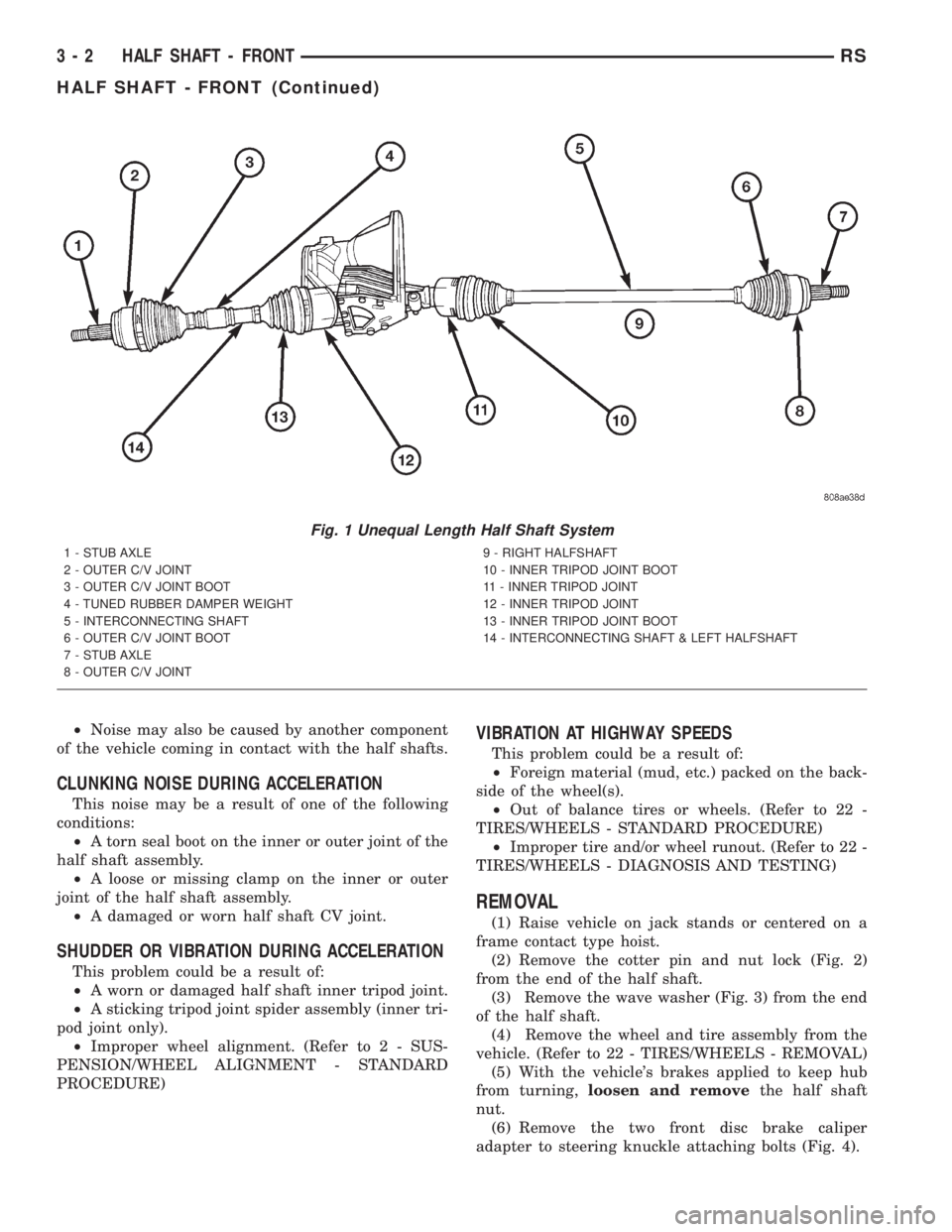
Fig. 1 Unequal Length Half Shaft System
1 - STUB AXLE
2 - OUTER C/V JOINT
3 - OUTER C/V JOINT BOOT
4 - TUNED RUBBER DAMPER WEIGHT
5 - INTERCONNECTING SHAFT
6 - OUTER C/V JOINT BOOT
7 - STUB AXLE
8 - OUTER C/V JOINT9 - RIGHT HALFSHAFT
10 - INNER TRIPOD JOINT BOOT
11 - INNER TRIPOD JOINT
12 - INNER TRIPOD JOINT
13 - INNER TRIPOD JOINT BOOT
14 - INTERCONNECTING SHAFT & LEFT HALFSHAFT
3 - 2 HALF SHAFT - FRONTRS
HALF SHAFT - FRONT (Continued)
Page 1674 of 4284
BRAKE ROTOR LIMITS
Braking RotorRotor
ThicknessMinimum
Rotor
ThicknessRotor
Thickness
VariationRotor
Runout*
Front Rotor -
Disc/Drum Brakes
(TRW)27.87±28.13
mm
1.097-1.107
in.25.3 mm
0.996 in.0.009 mm
0.0004 in.0.035 mm
0.0014 in.
Front Rotor -
Disc/Disc Brakes
(Teves)27.90±28.10
mm
1.098-1.106
in.25.3 mm
0.996 in.0.008 mm
0.0003 in.0.035 mm
0.0014 in.
Rear Rotor12.25±12.75
mm
0.482 -0.502
in.11.25 mm
0.443 in.0.013 mm
0.0005 in.0.14 mm
0.0055 in.
*
TIR Total Indicator Reading (Measured On Vehicle)
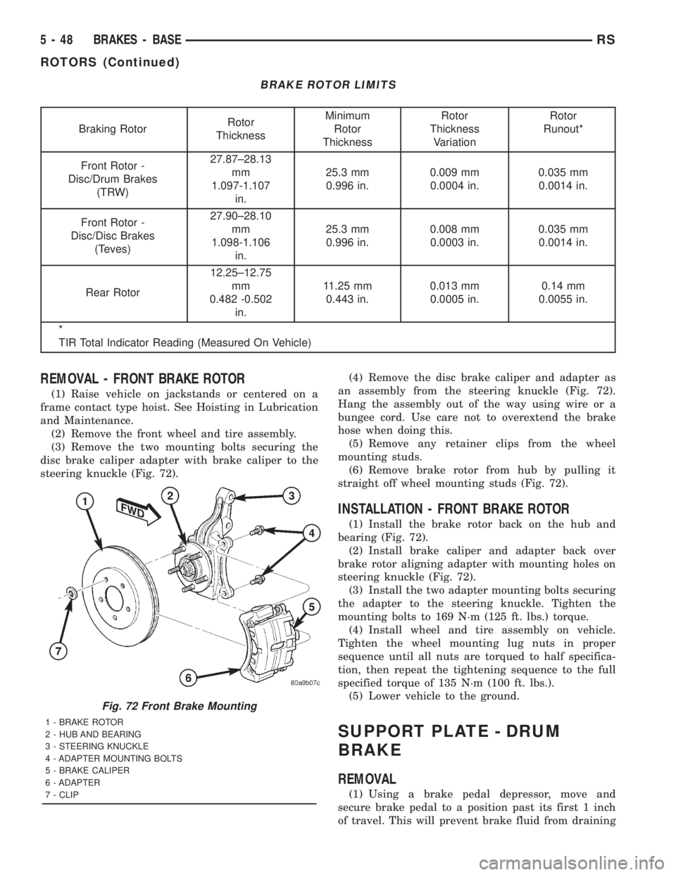
REMOVAL - FRONT BRAKE ROTOR
(1) Raise vehicle on jackstands or centered on a
frame contact type hoist. See Hoisting in Lubrication
and Maintenance.
(2) Remove the front wheel and tire assembly.
(3) Remove the two mounting bolts securing the
disc brake caliper adapter with brake caliper to the
steering knuckle (Fig. 72).(4) Remove the disc brake caliper and adapter as
an assembly from the steering knuckle (Fig. 72).
Hang the assembly out of the way using wire or a
bungee cord. Use care not to overextend the brake
hose when doing this.
(5) Remove any retainer clips from the wheel
mounting studs.
(6) Remove brake rotor from hub by pulling it
straight off wheel mounting studs (Fig. 72).
INSTALLATION - FRONT BRAKE ROTOR
(1) Install the brake rotor back on the hub and
bearing (Fig. 72).
(2) Install brake caliper and adapter back over
brake rotor aligning adapter with mounting holes on
steering knuckle (Fig. 72).
(3) Install the two adapter mounting bolts securing
the adapter to the steering knuckle. Tighten the
mounting bolts to 169 N´m (125 ft. lbs.) torque.
(4) Install wheel and tire assembly on vehicle.
Tighten the wheel mounting lug nuts in proper
sequence until all nuts are torqued to half specifica-
tion, then repeat the tightening sequence to the full
specified torque of 135 N´m (100 ft. lbs.).
(5) Lower vehicle to the ground.
SUPPORT PLATE - DRUM
BRAKE
REMOVAL
(1) Using a brake pedal depressor, move and
secure brake pedal to a position past its first 1 inch
of travel. This will prevent brake fluid from draining
Fig. 72 Front Brake Mounting
1 - BRAKE ROTOR
2 - HUB AND BEARING
3 - STEERING KNUCKLE
4 - ADAPTER MOUNTING BOLTS
5 - BRAKE CALIPER
6 - ADAPTER
7 - CLIP
5 - 48 BRAKES - BASERS
ROTORS (Continued)
Page 1688 of 4284
REMOVAL - PARKING BRAKE CABLE
(INTERMEDIATE)
(1) Raise the vehicle. (Refer to LUBRICATION &
MAINTENANCE/HOISTING - STANDARD PROCE-
DURE).
(2) Manually lock out the automatic self-adjusting
mechanism tension of the parking brake lever (pedal)
assembly. (Refer to 5 - BRAKES - STANDARD PRO-
CEDURE). Once the cable is released from the equal-
izer, do not remove the locking pliers until
reinstallation of the cable is complete.
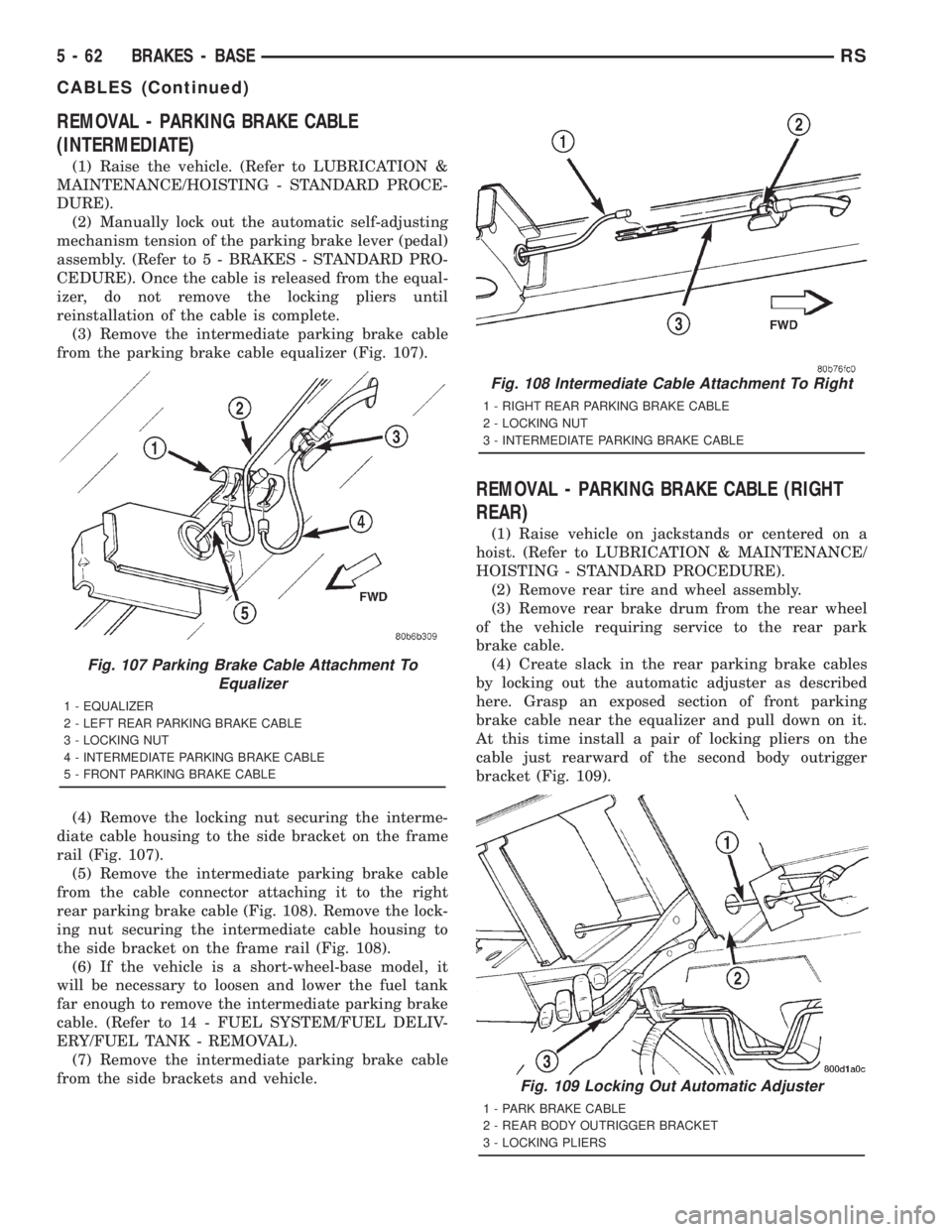
(3) Remove the intermediate parking brake cable
from the parking brake cable equalizer (Fig. 107).
(4) Remove the locking nut securing the interme-
diate cable housing to the side bracket on the frame
rail (Fig. 107).
(5) Remove the intermediate parking brake cable
from the cable connector attaching it to the right
rear parking brake cable (Fig. 108). Remove the lock-
ing nut securing the intermediate cable housing to
the side bracket on the frame rail (Fig. 108).
(6) If the vehicle is a short-wheel-base model, it
will be necessary to loosen and lower the fuel tank
far enough to remove the intermediate parking brake
cable. (Refer to 14 - FUEL SYSTEM/FUEL DELIV-
ERY/FUEL TANK - REMOVAL).
(7) Remove the intermediate parking brake cable
from the side brackets and vehicle.
REMOVAL - PARKING BRAKE CABLE (RIGHT
REAR)
(1) Raise vehicle on jackstands or centered on a
hoist. (Refer to LUBRICATION & MAINTENANCE/
HOISTING - STANDARD PROCEDURE).
(2) Remove rear tire and wheel assembly.
(3) Remove rear brake drum from the rear wheel
of the vehicle requiring service to the rear park
brake cable.
(4) Create slack in the rear parking brake cables
by locking out the automatic adjuster as described
here. Grasp an exposed section of front parking
brake cable near the equalizer and pull down on it.
At this time install a pair of locking pliers on the
cable just rearward of the second body outrigger
bracket (Fig. 109).
Fig. 107 Parking Brake Cable Attachment To
Equalizer
1 - EQUALIZER
2 - LEFT REAR PARKING BRAKE CABLE
3 - LOCKING NUT
4 - INTERMEDIATE PARKING BRAKE CABLE
5 - FRONT PARKING BRAKE CABLE
Fig. 108 Intermediate Cable Attachment To Right
1 - RIGHT REAR PARKING BRAKE CABLE
2 - LOCKING NUT
3 - INTERMEDIATE PARKING BRAKE CABLE
Fig. 109 Locking Out Automatic Adjuster
1 - PARK BRAKE CABLE
2 - REAR BODY OUTRIGGER BRACKET
3 - LOCKING PLIERS
5 - 62 BRAKES - BASERS
CABLES (Continued)
Page 1691 of 4284
INSTALLATION - PARKING BRAKE CABLE
(FRONT)
(1) Pass front parking brake cable assembly
through hole in floor pan from the inside of the vehi-
cle.
(2) Pass cable strand button through the hole in
the lever (pedal) assembly bracket.
(3) Install cable retainer onto the park brake cable
and then install cable retainer into pedal assembly
bracket.
(4) Install the end of the park brake cable into the
retainer previously installed into the park brake
pedal bracket.
(5) Install cable strand button into the clevis on
the park brake pedal mechanism.
(6) Install the front park brake cable floor pan seal
into hole in floor pan . Seal is to be installed so the
flange on the seal is flush with the floor pan (Fig.
106). Fold carpeting back down on floor.
(7) Raise vehicle.
(8) Insert brake cable and housing into body out-
rigger bracket making certain that housing retainer
fingers lock the housing firmly into place (Fig. 105).
(9) Manually reset the automatic self-adjusting
mechanism tension of the parking brake lever (pedal)
assembly. (Refer to 5 - BRAKES - STANDARD PRO-
CEDURE).
(10) Assemble the park brake cables onto the park
brake cable equalizer (Fig. 104).
(11) Lower vehicle and apply the park brake pedal
1 time. This will seat the parking brake cables.
INSTALLATION - PARKING BRAKE CABLE
(INTERMEDIATE)
(1) Install the ends of the park brake cables
through the frame rails and into the side brackets.
(2) Install the locking nuts at each end of the cable
and securely tighten (Fig. 107) (Fig. 108).
(3) If the vehicle is a short-wheel-base model, it
will be necessary to reinstall the fuel tank to its nor-
mal mounting position. (Refer to 14 - FUEL SYS-
TEM/FUEL DELIVERY/FUEL TANK -
INSTALLATION).(4) Install the intermediate parking brake cable on
the cable connector at the right rear parking brake
cable (Fig. 108).
(5) Install the intermediate park brake cable on
the cable equalizer (Fig. 107).
(6) Remove the locking pliers from the front park
brake cable. This will activate the automatic adjuster
and correctly adjust the parking brake cables.
(7) Install and position the foam collar on the
parking brake cable to prevent it from rattling
against the vehicle's floor.
(8) Lower the vehicle and apply the park brake
pedal 1 time, this will seat the park brake cables.
INSTALLATION - PARKING BRAKE CABLE
(RIGHT REAR)
(1) Install the rear parking brake cable in the
brake support plate. Insert cable housing retainer
into brake support plate making certain that cable
housing retainer fingers lock the housing and
retainer firmly into place.
(2) Attach the parking brake cable onto the park-
ing brake actuator lever.
(3) Install the brake shoes on the rear brake sup-
port plate. (Refer to 5 - BRAKES/HYDRAULIC/ME-
CHANICAL/BRAKE PADS/SHOES -
INSTALLATION).
(4) Insert cable housing retainer into body outrig-
ger bracket making certain that cable housing
retainer fingers lock the housing firmly into place.
(5) Connect the right rear parking brake cable to
the connector on the intermediate parking brake
cable (Fig. 110).
(6) Install the brake drum, then the wheel and tire
assembly.
(7) Remove the locking pliers from the front park
brake cable. This will automatically adjust the park
brake cables.
(8) Lower the vehicle.
(9) Apply and release park brake pedal 1 time.
This will seat the park brake cables.
RSBRAKES - BASE5-65
CABLES (Continued)