2001 CHRYSLER VOYAGER CD player
[x] Cancel search: CD playerPage 222 of 4284
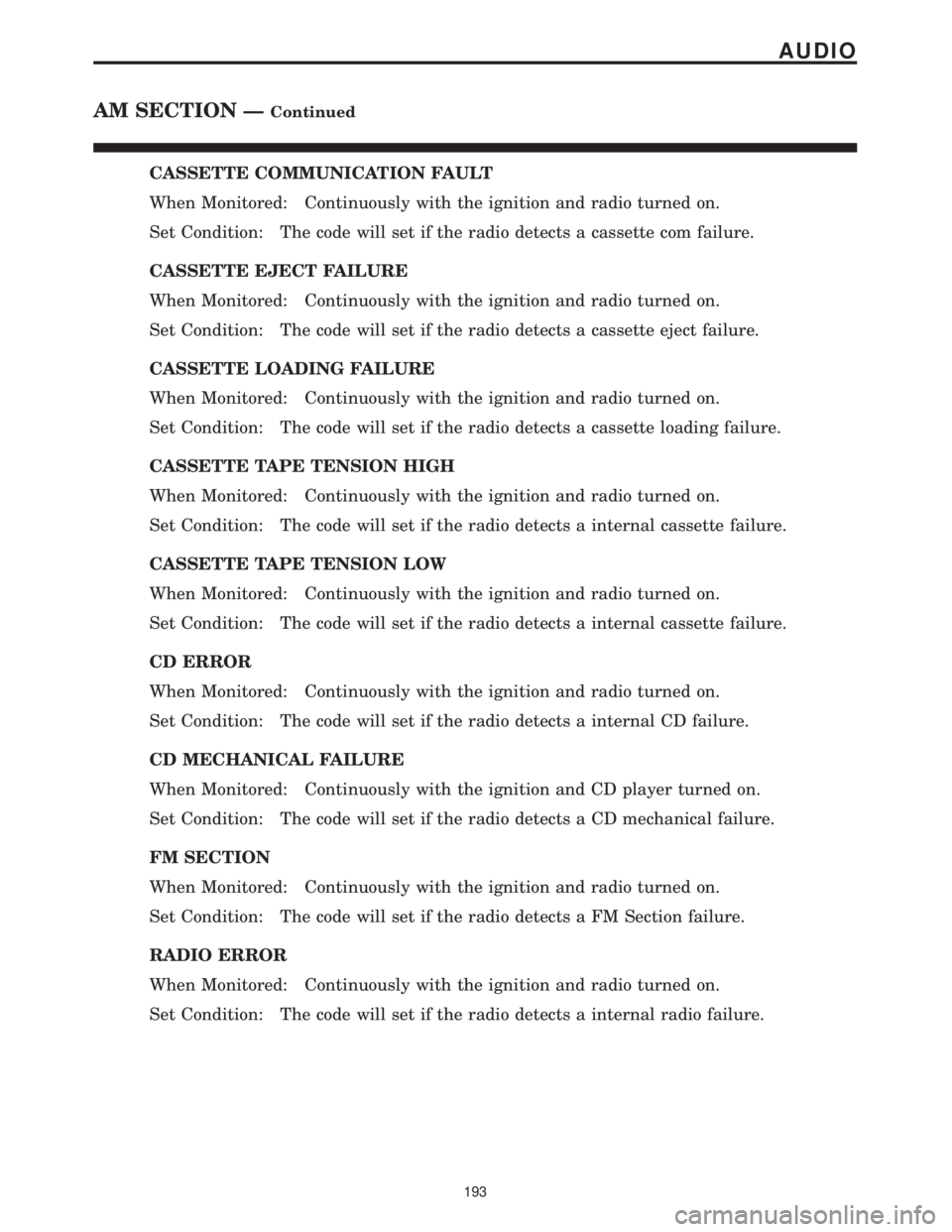
CASSETTE COMMUNICATION FAULT
When Monitored: Continuously with the ignition and radio turned on.
Set Condition: The code will set if the radio detects a cassette com failure.
CASSETTE EJECT FAILURE
When Monitored: Continuously with the ignition and radio turned on.
Set Condition: The code will set if the radio detects a cassette eject failure.
CASSETTE LOADING FAILURE
When Monitored: Continuously with the ignition and radio turned on.
Set Condition: The code will set if the radio detects a cassette loading failure.
CASSETTE TAPE TENSION HIGH
When Monitored: Continuously with the ignition and radio turned on.
Set Condition: The code will set if the radio detects a internal cassette failure.
CASSETTE TAPE TENSION LOW
When Monitored: Continuously with the ignition and radio turned on.
Set Condition: The code will set if the radio detects a internal cassette failure.
CD ERROR
When Monitored: Continuously with the ignition and radio turned on.
Set Condition: The code will set if the radio detects a internal CD failure.
CD MECHANICAL FAILURE
When Monitored: Continuously with the ignition and CD player turned on.
Set Condition: The code will set if the radio detects a CD mechanical failure.
FM SECTION
When Monitored: Continuously with the ignition and radio turned on.
Set Condition: The code will set if the radio detects a FM Section failure.
RADIO ERROR
When Monitored: Continuously with the ignition and radio turned on.
Set Condition: The code will set if the radio detects a internal radio failure.
193
AUDIO
AM SECTION ÐContinued
Page 228 of 4284
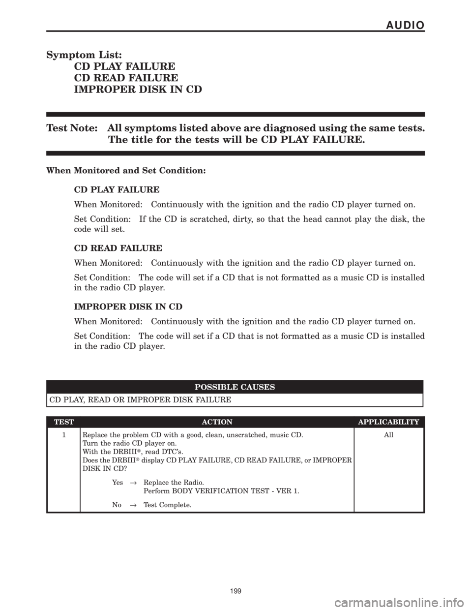
Symptom List:
CD PLAY FAILURE
CD READ FAILURE
IMPROPER DISK IN CD
Test Note: All symptoms listed above are diagnosed using the same tests.
The title for the tests will be CD PLAY FAILURE.
When Monitored and Set Condition:
CD PLAY FAILURE
When Monitored: Continuously with the ignition and the radio CD player turned on.
Set Condition: If the CD is scratched, dirty, so that the head cannot play the disk, the
code will set.
CD READ FAILURE
When Monitored: Continuously with the ignition and the radio CD player turned on.
Set Condition: The code will set if a CD that is not formatted as a music CD is installed
in the radio CD player.
IMPROPER DISK IN CD
When Monitored: Continuously with the ignition and the radio CD player turned on.
Set Condition: The code will set if a CD that is not formatted as a music CD is installed
in the radio CD player.
POSSIBLE CAUSES
CD PLAY, READ OR IMPROPER DISK FAILURE
TEST ACTION APPLICABILITY
1 Replace the problem CD with a good, clean, unscratched, music CD.
Turn the radio CD player on.
With the DRBIIIt, read DTC's.
Does the DRBIIItdisplay CD PLAY FAILURE, CD READ FAILURE, or IMPROPER
DISK IN CD?All
Ye s®Replace the Radio.
Perform BODY VERIFICATION TEST - VER 1.
No®Test Complete.
199
AUDIO
Page 229 of 4284
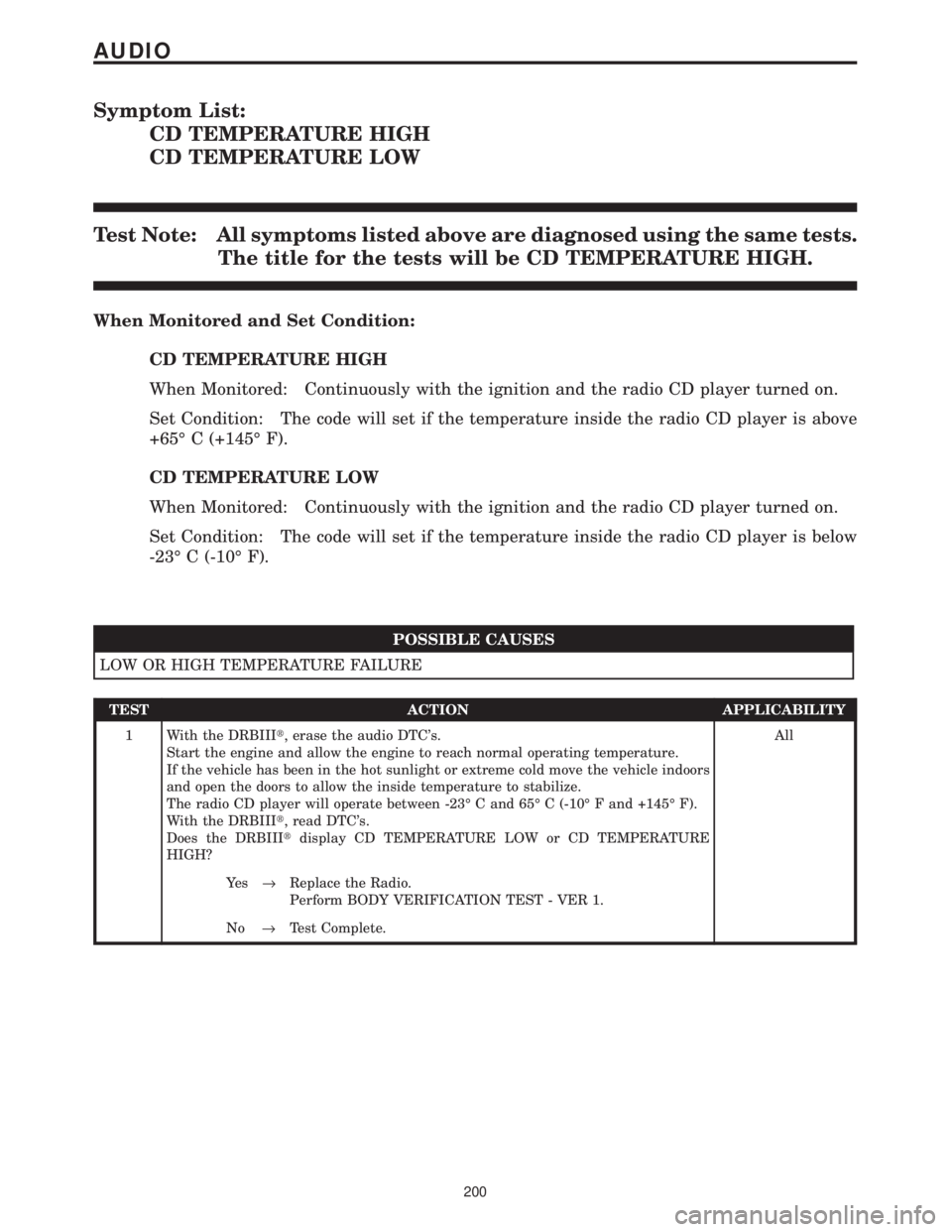
Symptom List:
CD TEMPERATURE HIGH
CD TEMPERATURE LOW
Test Note: All symptoms listed above are diagnosed using the same tests.
The title for the tests will be CD TEMPERATURE HIGH.
When Monitored and Set Condition:
CD TEMPERATURE HIGH
When Monitored: Continuously with the ignition and the radio CD player turned on.
Set Condition: The code will set if the temperature inside the radio CD player is above
+65É C (+145É F).
CD TEMPERATURE LOW
When Monitored: Continuously with the ignition and the radio CD player turned on.
Set Condition: The code will set if the temperature inside the radio CD player is below
-23É C (-10É F).
POSSIBLE CAUSES
LOW OR HIGH TEMPERATURE FAILURE
TEST ACTION APPLICABILITY
1 With the DRBIIIt, erase the audio DTC's.
Start the engine and allow the engine to reach normal operating temperature.
If the vehicle has been in the hot sunlight or extreme cold move the vehicle indoors
and open the doors to allow the inside temperature to stabilize.
The radio CD player will operate between -23É C and 65É C (-10É F and +145É F).
With the DRBIIIt, read DTC's.
Does the DRBIIItdisplay CD TEMPERATURE LOW or CD TEMPERATURE
HIGH?All
Ye s®Replace the Radio.
Perform BODY VERIFICATION TEST - VER 1.
No®Test Complete.
200
AUDIO
Page 1805 of 4284
AUDIO
TABLE OF CONTENTS
page page
AUDIO
DESCRIPTION............................1
OPERATION.............................1
DIAGNOSIS AND TESTING..................1
ANTENNA BODY & CABLE
DESCRIPTION............................3
OPERATION.............................3
DIAGNOSIS AND TESTING..................3
REMOVAL...............................4
INSTALLATION............................4
CD CHANGER
DESCRIPTION............................6
OPERATION.............................6
REMOVAL...............................6
INSTALLATION............................6
CHOKE
DIAGNOSIS AND TESTING..................6
D-PILLAR SPEAKER
REMOVAL...............................6
INSTALLATION............................7
DASH PANEL SPEAKER
REMOVAL...............................7INSTALLATION............................7
DOOR MOUNTED SPEAKER
REMOVAL...............................7
INSTALLATION............................7
QUARTER PANEL SPEAKER
REMOVAL...............................8
INSTALLATION............................8
RADIO
DIAGNOSIS AND TESTING..................8
REMOVAL...............................9
INSTALLATION............................9
RADIO NOISE SUPPRESSION COMPONENTS
DESCRIPTION............................9
OPERATION.............................9
REMOTE SWITCHES
DESCRIPTION...........................10
OPERATION.............................10
DIAGNOSIS AND TESTING.................11
REMOVAL..............................11
INSTALLATION...........................12
AUDIO
DESCRIPTION
There are four different system combinations avail-
able on the RS models. The available radio options
are:
²AM/FM Cassette
²AM/FM Compact Disc with Compact Disc
Changer
²AM/FM Cassette with single Compact Disc
Player
²AM/FM Cassette with Compact Disc Changer
All factory installed radio receivers are stereo Elec-
tronically Tuned Radios (ETR) and include and elec-
tronic digital clock function.
OPERATION
Operating instructions for the factory installed
audio systems can be found in the Owner's Manual
provided with this vehicle.
DIAGNOSIS AND TESTING
WARNING:
ON VEHICLES EQUIPPED WITH AIRBAGS, REFER
TO ELECTRICAL, RESTRAINTS BEFORE ATTEMPT-
ING ANY STEERING WHEEL, STEERING COLUMN,
OR INSTRUMENT PANEL COMPONENT DIAGNOSIS
OR SERVICE. FAILURE TO TAKE THE PROPER
PRECAUTIONS COULD RESULT IN ACCIDENTAL
AIRBAG DEPLOYMENT AND POSSIBLE PERSONAL
INJURY.
RSAUDIO8A-1
Page 1807 of 4284
CONDITION POSSIBLE CAUSE CORRECTION
4. POOR ANTENNA
CONNECTION AT
RADIO OR IN LINE.4. SEAT CONNECTOR.
NO/POOR TAPE
OPERATION.1. FAULTY TAPE. 1. INSERT KNOWN GOOD TAPE AND TEST OPERATION.
2. FOREIGN OBJECTS
BEHIND TAPE DOOR.2. REMOVE FOREIGN OBJECTS AND TEST OPERATION.
3. DIRTY CASSETTE
TAPE HEAD.3. CLEAN HEAD WITH MOPAR CASSETTE HEAD CLEANER.
4. FAULTY TAPE DECK. 4. EXCHANGE OR REPLACE RADIO, IF REQUIRED.
NO COMPACT
DISC
OPERATION1. FAULTY CD. 1. INSERT KNOWN GOOD CD AND TEST OPERATION.
2. FOREIGN MATERIAL
ON CD.2. CLEAN CD AND TEST OPERATION.
3. CONDENSATION ON
CD OR OPTICS.3. ALLOW TEMPERATURE OF VEHICLE INTERIOR TO
STABILIZE AND TEST OPERATION.
4. FAULTY CD PLAYER. 4. EXCHANGE OR REPLACE RADIO, IF REQUIRED.
ANTENNA BODY & CABLE
DESCRIPTION
All models use a fixed-length stainless steel rod-
type antenna mast, installed at the right front fender
of the vehicle. The antenna mast is connected to the
center wire of the coaxial antenna cable, and is not
grounded to any part of the vehicle.
OPERATION
To minimize static, the antenna base must have a
good ground. The coaxial antenna cable shield (the
outer wire mesh of the cable) is grounded to the
antenna base and the radio chassis.
The antenna coaxial cable has an additional dis-
connect, located near the right end of the instrument
panel. This additional disconnect allows the instru-
ment panel assembly to be removed and installed
without removing the radio.
The factory-installed Electronically Tuned Radios
(ETRs) automatically compensate for radio antenna
trim. Therefore, no antenna trimmer adjustment is
required or possible when replacing the receiver or
the antenna.
DIAGNOSIS AND TESTING
WARNING:
ON VEHICLES EQUIPPED WITH AIRBAGS, REFER
TO ELECTRICAL, RESTRAINTS BEFORE ATTEMPT-ING ANY STEERING WHEEL, STEERING COLUMN,
OR INSTRUMENT PANEL COMPONENT DIAGNOSIS
OR SERVICE. FAILURE TO TAKE THE PROPER
PRECAUTIONS COULD RESULT IN ACCIDENTAL
AIRBAG DEPLOYMENT AND POSSIBLE PERSONAL
INJURY.
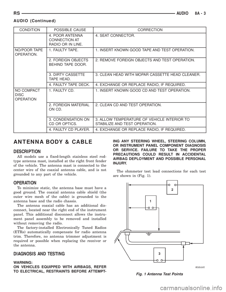
The ohmmeter test lead connections for each test
are shown in (Fig. 1).
Fig. 1 Antenna Test Points
RSAUDIO8A-3
AUDIO (Continued)
Page 1810 of 4284
CD CHANGER
DESCRIPTION
The 4 Disc In-Dash CD Changer (if equipped) is
located in the instrument panel below the radio. The
remote changer does not use a cartridge or magazine
for the CD's. Up to 4 CD's can be directly loaded into
this unit.
OPERATION
Due to its compact design, the CD changer can
carry out only one operation at a time. For example,
you can not load a new disc while playing another at
the same time. Each operation happens sequentially.
The radio unit provides control over all features of
the CD changer with the exception of the CD load
and eject functions, which are controlled by buttons
located on the front of the CD changer. All features
you would expect, such as Disc Up/Down, Track
Up/Down, Random and Scan are controlled by the
radio, which also displays all relevant CD changer
information on the radio display.
The CD changer contains a Load/Eject button and
an indicator LED for each of the four disc positions
as well as an illuminated disc opening. The individ-
ual LED indicates whether a CD is currently loaded
in that particular chamber of the CD changer. Press-
ing the individual Load/Eject button for a particular
chamber will eject a disc currently present in that
chamber. If the chamber is currently empty, actuat-
ing the Load/Eject button will position that chamber
to receive and load a new disc in that chamber.
REMOVAL
(1) Disconnect and isolate the battery negative
cable.
(2) Remove screws holding CD changer.
(3) Disconnect the wire connector from the back of
the CD changer.
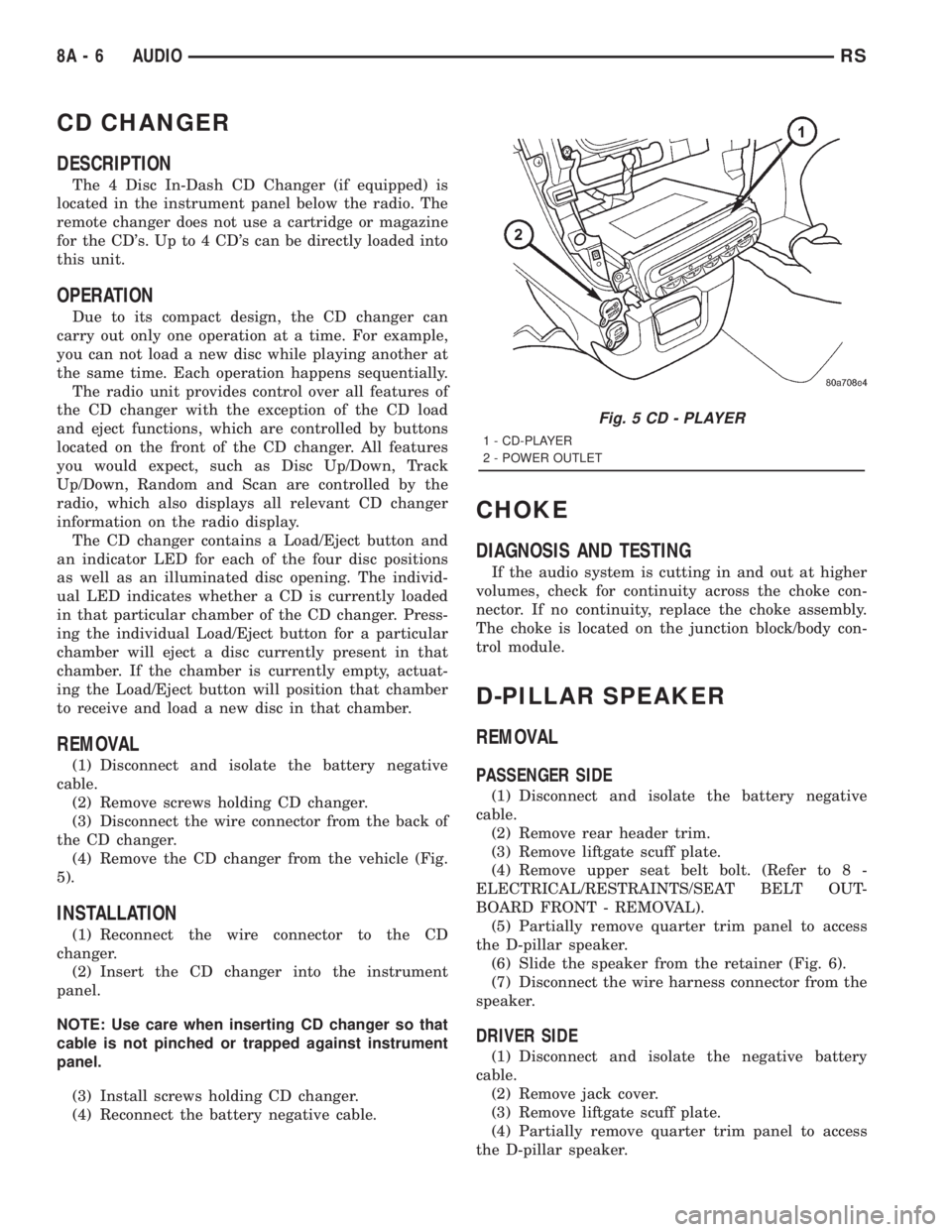
(4) Remove the CD changer from the vehicle (Fig.
5).
INSTALLATION
(1) Reconnect the wire connector to the CD
changer.
(2) Insert the CD changer into the instrument
panel.
NOTE: Use care when inserting CD changer so that
cable is not pinched or trapped against instrument
panel.
(3) Install screws holding CD changer.
(4) Reconnect the battery negative cable.
CHOKE
DIAGNOSIS AND TESTING
If the audio system is cutting in and out at higher
volumes, check for continuity across the choke con-
nector. If no continuity, replace the choke assembly.
The choke is located on the junction block/body con-
trol module.
D-PILLAR SPEAKER
REMOVAL
PASSENGER SIDE
(1) Disconnect and isolate the battery negative
cable.
(2) Remove rear header trim.
(3) Remove liftgate scuff plate.
(4) Remove upper seat belt bolt. (Refer to 8 -
ELECTRICAL/RESTRAINTS/SEAT BELT OUT-
BOARD FRONT - REMOVAL).
(5) Partially remove quarter trim panel to access
the D-pillar speaker.
(6) Slide the speaker from the retainer (Fig. 6).
(7) Disconnect the wire harness connector from the
speaker.
DRIVER SIDE
(1) Disconnect and isolate the negative battery
cable.
(2) Remove jack cover.
(3) Remove liftgate scuff plate.
(4) Partially remove quarter trim panel to access
the D-pillar speaker.
Fig. 5 CD - PLAYER
1 - CD-PLAYER
2 - POWER OUTLET
8A - 6 AUDIORS
Page 1812 of 4284
(4) Connect battery negative cable.
QUARTER PANEL SPEAKER
REMOVAL
(1) Disconnect and isolate the battery negative
cable.
(2) Remove speaker grill by prying away from trim
panel.
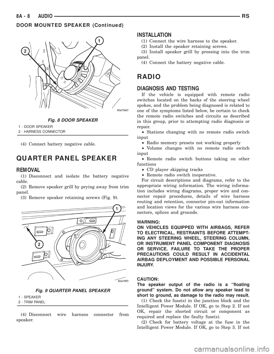
(3) Remove speaker retaining screws (Fig. 9).
(4) Disconnect wire harness connector from
speaker.
INSTALLATION
(1) Connect the wire harness to the speaker.
(2) Install the speaker retaining screws.
(3) Install speaker grill by pressing into the trim
panel.
(4) Connect the battery negative cable.
RADIO
DIAGNOSIS AND TESTING
If the vehicle is equipped with remote radio
switches located on the backs of the steering wheel
spokes, and the problem being diagnosed is related to
one of the symptoms listed below, be certain to check
the remote radio switches and circuits as described
in this group, prior to attempting radio diagnosis or
repair.
²Stations changing with no remote radio switch
input
²Radio memory presets not working properly
²Volume changes with no remote radio switch
input
²Remote radio switch buttons taking on other
functions
²CD player skipping tracks
²Remote radio switch inoperative.
For circuit descriptions and diagrams, refer to the
appropriate wiring information. The wiring informa-
tion includes wiring diagrams, proper wire and con-
nector repair procedures, details of wire harness
routing and retention, connector pin-out information
and location views for the various wire harness con-
nectors, splices and grounds.
WARNING:
ON VEHICLES EQUIPPED WITH AIRBAGS, REFER
TO ELECTRICAL, RESTRAINTS BEFORE ATTEMPT-
ING ANY STEERING WHEEL, STEERING COLUMN,
OR INSTRUMENT PANEL COMPONENT DIAGNOSIS
OR SERVICE. FAILURE TO TAKE THE PROPER
PRECAUTIONS COULD RESULT IN ACCIDENTAL
AIRBAG DEPLOYMENT AND POSSIBLE PERSONAL
INJURY.
CAUTION:
The speaker output of the radio is a ªfloating
groundº system. Do not allow any speaker lead to
short to ground, as damage to the radio may result.
(1) Check the fuse(s) in the junction block and the
Intelligent Power Module. If OK, go to Step 2. If not
OK, repair the shorted circuit or component as
required and replace the faulty fuse(s).
(2) Check for battery voltage at the fuse in the
Intelligent Power Module. If OK, go to Step 3. If not
Fig. 8 DOOR SPEAKER
1 - DOOR SPEAKER
2 - HARNESS CONNECTOR
Fig. 9 QUARTER PANEL SPEAKER
1 - SPEAKER
2 - TRIM PANEL
8A - 8 AUDIORS
DOOR MOUNTED SPEAKER (Continued)
Page 1813 of 4284
OK, repair the open circuit to the battery as
required.
(3) Turn the ignition switch to the ON position.
Check for battery voltage at the fuse in the junction
block. If OK, go to Step 4. If not OK, repair the open
circuit to the ignition switch as required.
(4) Turn the ignition switch to the OFF position.
Disconnect and isolate the battery negative cable.
Remove the radio, but do not unplug the wire har-
ness connectors. Check for continuity between the
radio chassis and a good ground. There should be
continuity. If OK, go to Step 5. If not OK, repair the
open radio chassis ground circuit as required.
(5) Connect the battery negative cable. Turn the
ignition switch to the ON position. Check for battery
voltage at the fused ignition switch output circuit
cavity of the left (gray) radio wire harness connector.
If OK, go to Step 6. If not OK, repair the open circuit
as required.
(6) Turn the ignition switch to the OFF position.
Check for battery voltage at the fused B(+) circuit
cavity of the left (gray) radio wire harness connector.
If OK, replace the faulty radio. If not OK, repair the
open circuit to the Ignition-Off Draw (IOD) fuse as
required.
REMOVAL
(1) Disconnect and isolate the battery negative
cable.
(2) Remove cup holder.
(3) Remove trim panel above cupholder by pulling
straight out.
(4) Remove center instrument panel trim panel.
(5) Remove screws holding radio to instrument
panel.
(6) Pull radio rearward to gain access to the back
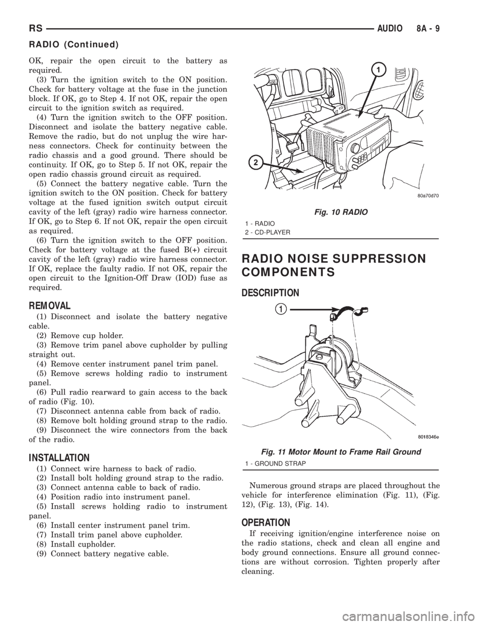
of radio (Fig. 10).
(7) Disconnect antenna cable from back of radio.
(8) Remove bolt holding ground strap to the radio.
(9) Disconnect the wire connectors from the back
of the radio.
INSTALLATION
(1) Connect wire harness to back of radio.
(2) Install bolt holding ground strap to the radio.
(3) Connect antenna cable to back of radio.
(4) Position radio into instrument panel.
(5) Install screws holding radio to instrument
panel.
(6) Install center instrument panel trim.
(7) Install trim panel above cupholder.
(8) Install cupholder.
(9) Connect battery negative cable.
RADIO NOISE SUPPRESSION
COMPONENTS
DESCRIPTION
Numerous ground straps are placed throughout the
vehicle for interference elimination (Fig. 11), (Fig.
12), (Fig. 13), (Fig. 14).
OPERATION
If receiving ignition/engine interference noise on
the radio stations, check and clean all engine and
body ground connections. Ensure all ground connec-
tions are without corrosion. Tighten properly after
cleaning.
Fig. 10 RADIO
1 - RADIO
2 - CD-PLAYER
Fig. 11 Motor Mount to Frame Rail Ground
1 - GROUND STRAP
RSAUDIO8A-9
RADIO (Continued)