2001 CHRYSLER VOYAGER bolt pattern
[x] Cancel search: bolt patternPage 1522 of 4284
INSTALLATION - HUB AND BEARING
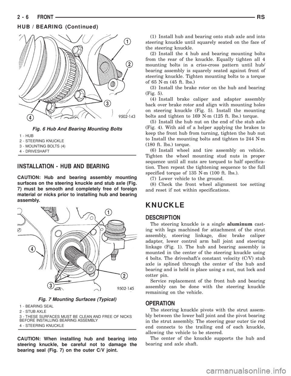
CAUTION: Hub and bearing assembly mounting
surfaces on the steering knuckle and stub axle (Fig.
7) must be smooth and completely free of foreign
material or nicks prior to installing hub and bearing
assembly.
CAUTION: When installing hub and bearing into
steering knuckle, be careful not to damage the
bearing seal (Fig. 7) on the outer C/V joint.(1) Install hub and bearing onto stub axle and into
steering knuckle until squarely seated on the face of
the steering knuckle.
(2) Install the 4 hub and bearing mounting bolts
from the rear of the knuckle. Equally tighten all 4
mounting bolts in a criss-cross pattern until hub/
bearing assembly is squarely seated against front of
steering knuckle. Tighten mounting bolts to a torque
of 65 N´m (45 ft. lbs.)
(3) Install the brake rotor on the hub and bearing
(Fig. 5).
(4) Install brake caliper and adapter assembly
back over brake rotor and align with mounting holes
on steering knuckle (Fig. 5). Install the mounting
bolts and tighten to 169 N´m (125 ft. lbs.) torque.
(5) Install the hub nut on the end of the stub axle
(Fig. 4). With aid of a helper applying the brakes to
keep the front hub from turning, tighten the hub nut
to Install the mounting bolts and tighten to 244 N´m
(180 ft. lbs.) torque.
(6) Install wheel and tire assembly on vehicle.
Tighten the wheel mounting stud nuts in proper
sequence until all nuts are torqued to half specifica-
tion. Then repeat the tightening sequence to the full
specified torque of 135 N´m (100 ft. lbs.).
(7) Lower vehicle to the ground.
(8) Check the front wheel alignment toe setting
and reset if not within specifications.
KNUCKLE
DESCRIPTION
The steering knuckle is a singlealuminumcast-
ing with legs machined for attachment of the strut
assembly, steering linkage, disc brake caliper
adapter, lower control arm ball joint and steering
linkage (Fig. 1). The hub and bearing assembly is
mounted in the center of the steering knuckle using
4 bolts. The driveshaft's constant velocity (C/V) stub
axle is splined through the center of the hub and
bearing and is held in place using a nut, nut lock and
cotter pin.
Service replacement of the front hub and bearing
assembly can be done with the steering knuckle
remaining on the vehicle.
OPERATION
The steering knuckle pivots with the strut assem-
bly between the lower ball joint and the pivot bearing
in the strut assembly. The steering gear outer tie rod
end connects to the trailing end of each knuckle,
allowing the vehicle to be steered.
The center of the knuckle supports the hub and
bearing and axle shaft.
Fig. 6 Hub And Bearing Mounting Bolts
1 - HUB
2 - STEERING KNUCKLE
3 - MOUNTING BOLTS (4)
4 - DRIVESHAFT
Fig. 7 Mounting Surfaces (Typical)
1 - BEARING SEAL
2 - STUB AXLE
3 - THESE SURFACES MUST BE CLEAN AND FREE OF NICKS
BEFORE INSTALLING BEARING ASSEMBLY
4 - STEERING KNUCKLE
2 - 6 FRONTRS
HUB / BEARING (Continued)
Page 1549 of 4284
INSTALLATION - HUB AND BEARING
FRONT-WHEEL-DRIVE VEHICLES
(1) Install the 4 hub and bearing to axle mounting
bolts into the holes in the flange of the rear axle.
(2) Install the rear brake support plate on the 4
mounting bolts installed in the flange of the rear
axle.
(3) Align the rear hub and bearing with the 4
mounting bolts and start mounting bolts into hub
and bearing. Tighten the 4 bolts in a crisscross pat-
tern until the hub nd bearing and brake support
plate is fully and squarely seated onto flange of rear
axle. Tighten the 4 mounting bolts to a torque of 129
N´m (95 ft. lbs.)
NOTE: If equipped with antilock brakes, make sure
wheel speed sensor stays clean and dry as it is
installed into the hub and bearing cap.
(4) If the vehicle is equipped with antilock brakes,
perform the following:
(a) If metal sensor retaining clip is not in the
neutral installed position on hub and bearing cap,
install from the bottom, if necessary, and push clip
upward until it snaps into position.
(b) Install wheel speed sensor head into rear of
hub and bearing aligning index tab with the notch
in the top of the mounting hole. Push the sensor in
until it snaps into place on the metal retaining
clip.
(c) Install secondary (yellow) retaining clip over
wheel speed sensor head and engage the tabs on
each side (Fig. 8).
(5) Install brake drum or disc brake rotor and
brake caliper. Refer to Brakes.
(6) Install wheel and tire. Tighten the wheel nuts
in the proper sequence to a torque of 135 N´m (100
ft. lbs.).
(7) Adjust the rear brakes as necessary. Refer to
Brakes.
(8) Lower vehicle.
(9) Road test vehicle to ensure proper operation of
brakes.
ALL-WHEEL-DRIVE VEHICLES
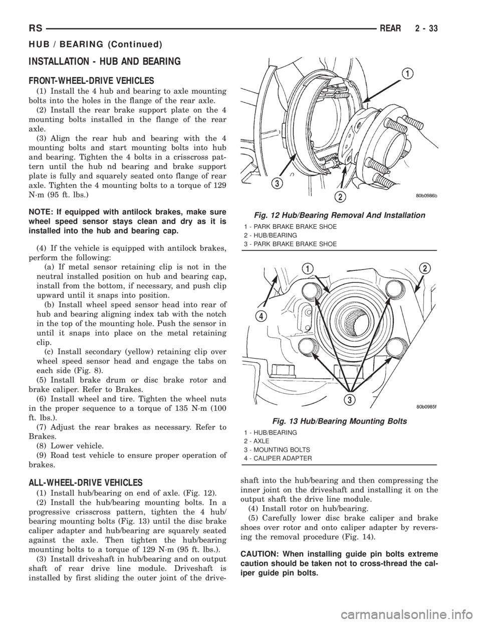
(1) Install hub/bearing on end of axle. (Fig. 12).
(2) Install the hub/bearing mounting bolts. In a
progressive crisscross pattern, tighten the 4 hub/
bearing mounting bolts (Fig. 13) until the disc brake
caliper adapter and hub/bearing are squarely seated
against the axle. Then tighten the hub/bearing
mounting bolts to a torque of 129 N´m (95 ft. lbs.).
(3) Install driveshaft in hub/bearing and on output
shaft of rear drive line module. Driveshaft is
installed by first sliding the outer joint of the drive-shaft into the hub/bearing and then compressing the
inner joint on the driveshaft and installing it on the
output shaft the drive line module.
(4) Install rotor on hub/bearing.
(5) Carefully lower disc brake caliper and brake
shoes over rotor and onto caliper adapter by revers-
ing the removal procedure (Fig. 14).
CAUTION: When installing guide pin bolts extreme
caution should be taken not to cross-thread the cal-
iper guide pin bolts.
Fig. 12 Hub/Bearing Removal And Installation
1 - PARK BRAKE BRAKE SHOE
2 - HUB/BEARING
3 - PARK BRAKE BRAKE SHOE
Fig. 13 Hub/Bearing Mounting Bolts
1 - HUB/BEARING
2 - AXLE
3 - MOUNTING BOLTS
4 - CALIPER ADAPTER
RSREAR2-33
HUB / BEARING (Continued)
Page 1684 of 4284
INSTALLATION
(1) Install the trailing brake shoe on the adapter.
NOTE: When the hold down pin is installed, the
long part of the hold down pin is to be positioned
strait up and down. This will ensure that the hold
down pin is correctly engaged with the adapter.
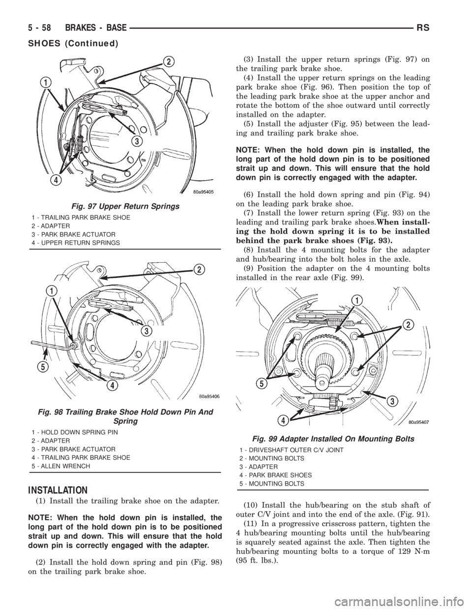
(2) Install the hold down spring and pin (Fig. 98)
on the trailing park brake shoe.(3) Install the upper return springs (Fig. 97) on
the trailing park brake shoe.
(4) Install the upper return springs on the leading
park brake shoe (Fig. 96). Then position the top of
the leading park brake shoe at the upper anchor and
rotate the bottom of the shoe outward until correctly
installed on the adapter.
(5) Install the adjuster (Fig. 95) between the lead-
ing and trailing park brake shoe.
NOTE: When the hold down pin is installed, the
long part of the hold down pin is to be positioned
strait up and down. This will ensure that the hold
down pin is correctly engaged with the adapter.
(6) Install the hold down spring and pin (Fig. 94)
on the leading park brake shoe.
(7) Install the lower return spring (Fig. 93) on the
leading and trailing park brake shoes.When install-
ing the hold down spring it is to be installed
behind the park brake shoes (Fig. 93).
(8) Install the 4 mounting bolts for the adapter
and hub/bearing into the bolt holes in the axle.
(9) Position the adapter on the 4 mounting bolts
installed in the rear axle (Fig. 99).
(10) Install the hub/bearing on the stub shaft of
outer C/V joint and into the end of the axle. (Fig. 91).
(11) In a progressive crisscross pattern, tighten the
4 hub/bearing mounting bolts until the hub/bearing
is squarely seated against the axle. Then tighten the
hub/bearing mounting bolts to a torque of 129 N´m
(95 ft. lbs.).
Fig. 97 Upper Return Springs
1 - TRAILING PARK BRAKE SHOE
2 - ADAPTER
3 - PARK BRAKE ACTUATOR
4 - UPPER RETURN SPRINGS
Fig. 98 Trailing Brake Shoe Hold Down Pin And
Spring
1 - HOLD DOWN SPRING PIN
2 - ADAPTER
3 - PARK BRAKE ACTUATOR
4 - TRAILING PARK BRAKE SHOE
5 - ALLEN WRENCHFig. 99 Adapter Installed On Mounting Bolts
1 - DRIVESHAFT OUTER C/V JOINT
2 - MOUNTING BOLTS
3 - ADAPTER
4 - PARK BRAKE SHOES
5 - MOUNTING BOLTS
5 - 58 BRAKES - BASERS
SHOES (Continued)
Page 1744 of 4284
CLEANING
Clean all foreign debris from belt pulley grooves.
The belt pulleys must be free of oil, grease, and cool-
ants before installing the drive belt.
INSPECTION
Belt replacement under any or all of the following
conditions is required:
²Excessive wear
²Frayed cords
²Severe glazing
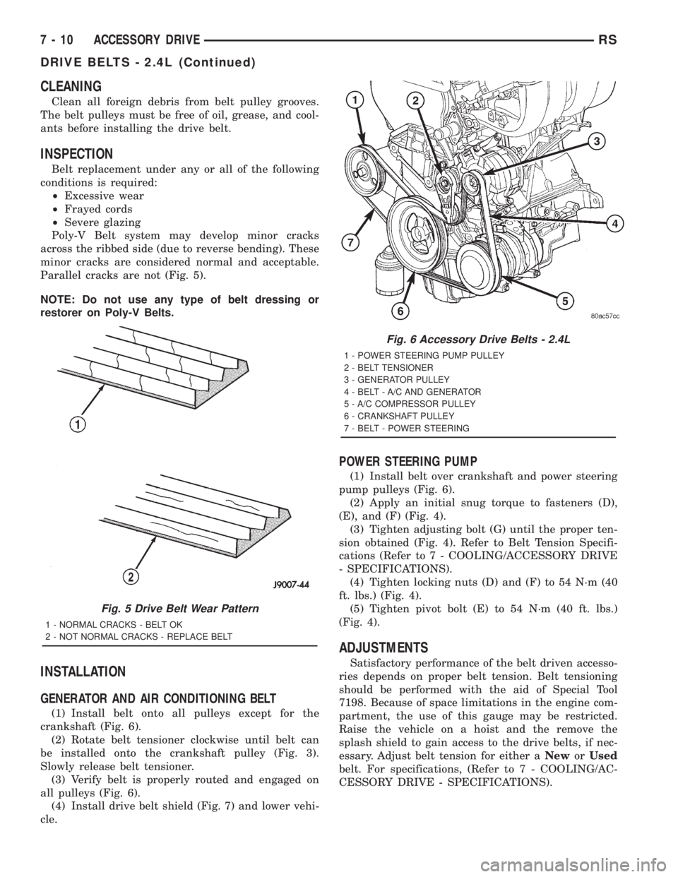
Poly-V Belt system may develop minor cracks
across the ribbed side (due to reverse bending). These
minor cracks are considered normal and acceptable.
Parallel cracks are not (Fig. 5).
NOTE: Do not use any type of belt dressing or
restorer on Poly-V Belts.
INSTALLATION
GENERATOR AND AIR CONDITIONING BELT
(1) Install belt onto all pulleys except for the
crankshaft (Fig. 6).
(2) Rotate belt tensioner clockwise until belt can
be installed onto the crankshaft pulley (Fig. 3).
Slowly release belt tensioner.
(3) Verify belt is properly routed and engaged on
all pulleys (Fig. 6).
(4) Install drive belt shield (Fig. 7) and lower vehi-
cle.
POWER STEERING PUMP
(1) Install belt over crankshaft and power steering
pump pulleys (Fig. 6).
(2) Apply an initial snug torque to fasteners (D),
(E), and (F) (Fig. 4).
(3) Tighten adjusting bolt (G) until the proper ten-
sion obtained (Fig. 4). Refer to Belt Tension Specifi-
cations (Refer to 7 - COOLING/ACCESSORY DRIVE
- SPECIFICATIONS).
(4) Tighten locking nuts (D) and (F) to 54 N´m (40
ft. lbs.) (Fig. 4).
(5) Tighten pivot bolt (E) to 54 N´m (40 ft. lbs.)
(Fig. 4).
ADJUSTMENTS
Satisfactory performance of the belt driven accesso-
ries depends on proper belt tension. Belt tensioning
should be performed with the aid of Special Tool
7198. Because of space limitations in the engine com-
partment, the use of this gauge may be restricted.
Raise the vehicle on a hoist and the remove the
splash shield to gain access to the drive belts, if nec-
essary. Adjust belt tension for either aNeworUsed
belt. For specifications, (Refer to 7 - COOLING/AC-
CESSORY DRIVE - SPECIFICATIONS).
Fig. 5 Drive Belt Wear Pattern
1 - NORMAL CRACKS - BELT OK
2 - NOT NORMAL CRACKS - REPLACE BELT
Fig. 6 Accessory Drive Belts - 2.4L
1 - POWER STEERING PUMP PULLEY
2 - BELT TENSIONER
3 - GENERATOR PULLEY
4 - BELT - A/C AND GENERATOR
5 - A/C COMPRESSOR PULLEY
6 - CRANKSHAFT PULLEY
7 - BELT - POWER STEERING
7 - 10 ACCESSORY DRIVERS
DRIVE BELTS - 2.4L (Continued)
Page 2730 of 4284
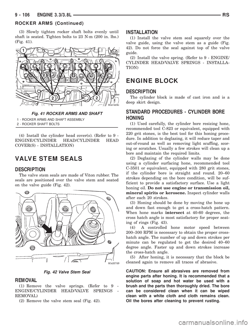
(3) Slowly tighten rocker shaft bolts evenly until
shaft is seated. Tighten bolts to 23 N´m (200 in. lbs.)
(Fig. 41).
(4) Install the cylinder head cover(s). (Refer to 9 -
ENGINE/CYLINDER HEAD/CYLINDER HEAD
COVER(S) - INSTALLATION)
VALVE STEM SEALS
DESCRIPTION
The valve stem seals are made of Viton rubber. The
seals are positioned over the valve stem and seated
on the valve guide (Fig. 42).
REMOVAL
(1) Remove the valve springs. (Refer to 9 -
ENGINE/CYLINDER HEAD/VALVE SPRINGS -
REMOVAL)
(2) Remove the valve stem seal (Fig. 42).
INSTALLATION
(1) Install the valve stem seal squarely over the
valve guide, using the valve stem as a guide (Fig.
42). Do not force the seal against top of the valve
guide.
(2) Install the valve spring. (Refer to 9 - ENGINE/
CYLINDER HEAD/VALVE SPRINGS - INSTALLA-
TION)
ENGINE BLOCK
DESCRIPTION
The cylinder block is made of cast iron and is a
deep skirt design.
STANDARD PROCEDURES - CYLINDER BORE
HONING
(1)Used carefully, the cylinder bore resizing hone,
recommended tool C-823 or equivalent, equipped with
220 grit stones, is the best tool for this honing proce-
dure. In addition to deglazing, it will reduce taper and
out-of-round as well as removing light scuffing, scor-
ing or scratches. Usually a few strokes will clean up a
bore and maintain the required limits.
(2) Deglazing of the cylinder walls may be done
using a cylinder surfacing hone, recommended tool
C-3501 or equivalent, equipped with 280 grit stones,
if the cylinder bore is straight and round. 20±60
strokes depending on the bore condition, will be suf-
ficient to provide a satisfactory surface. Use a light
honing oil.Do not use engine or transmission oil,
mineral spirits or kerosene.Inspect cylinder walls
after each 20 strokes.
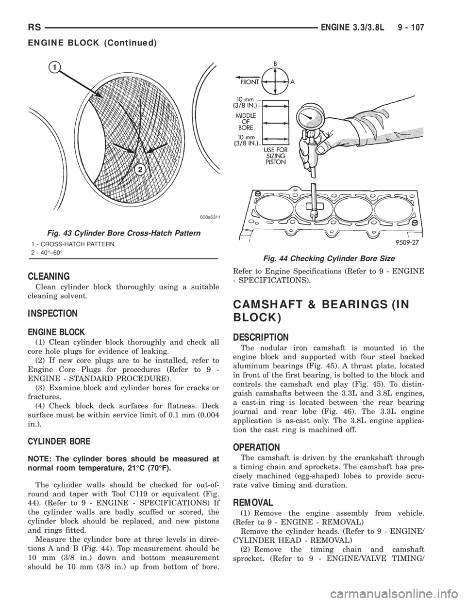
(3) Honing should be done by moving the hone up
and down fast enough to get a cross-hatch pattern.
When hone marksintersectat 40-60 degrees, the
cross hatch angle is most satisfactory for proper seat-
ing of rings (Fig. 43).
(4) A controlled hone motor speed between
200±300 RPM is necessary to obtain the proper cross-
hatch angle. The number of up and down strokes per
minute can be regulated to get the desired 40±60
degree angle. Faster up and down strokes increase
the cross-hatch angle.
(5) After honing, it is necessary that the block be
cleaned again to remove all traces of abrasive.
CAUTION: Ensure all abrasives are removed from
engine parts after honing. It is recommended that a
solution of soap and hot water be used with a
brush and the parts then thoroughly dried. The bore
can be considered clean when it can be wiped
clean with a white cloth and cloth remains clean.
Oil the bores after cleaning to prevent rusting.
Fig. 41 ROCKER ARMS AND SHAFT
1 - ROCKER ARMS AND SHAFT ASSEMBLY
2 - ROCKER SHAFT BOLTS
Fig. 42 Valve Stem Seal
9 - 106 ENGINE 3.3/3.8LRS
ROCKER ARMS (Continued)
Page 2731 of 4284
CLEANING
Clean cylinder block thoroughly using a suitable
cleaning solvent.
INSPECTION
ENGINE BLOCK
(1) Clean cylinder block thoroughly and check all
core hole plugs for evidence of leaking.
(2) If new core plugs are to be installed, refer to
Engine Core Plugs for procedures (Refer to 9 -
ENGINE - STANDARD PROCEDURE).
(3) Examine block and cylinder bores for cracks or
fractures.
(4) Check block deck surfaces for flatness. Deck
surface must be within service limit of 0.1 mm (0.004
in.).
CYLINDER BORE
NOTE: The cylinder bores should be measured at
normal room temperature, 21ÉC (70ÉF).
The cylinder walls should be checked for out-of-
round and taper with Tool C119 or equivalent (Fig.
44). (Refer to 9 - ENGINE - SPECIFICATIONS) If
the cylinder walls are badly scuffed or scored, the
cylinder block should be replaced, and new pistons
and rings fitted.
Measure the cylinder bore at three levels in direc-
tions A and B (Fig. 44). Top measurement should be
10 mm (3/8 in.) down and bottom measurement
should be 10 mm (3/8 in.) up from bottom of bore.Refer to Engine Specifications (Refer to 9 - ENGINE
- SPECIFICATIONS).
CAMSHAFT & BEARINGS (IN
BLOCK)
DESCRIPTION
The nodular iron camshaft is mounted in the
engine block and supported with four steel backed
aluminum bearings (Fig. 45). A thrust plate, located
in front of the first bearing, is bolted to the block and
controls the camshaft end play (Fig. 45). To distin-
guish camshafts between the 3.3L and 3.8L engines,
a cast-in ring is located between the rear bearing
journal and rear lobe (Fig. 46). The 3.3L engine
application is as-cast only. The 3.8L engine applica-
tion the cast ring is machined off.
OPERATION
The camshaft is driven by the crankshaft through
a timing chain and sprockets. The camshaft has pre-
cisely machined (egg-shaped) lobes to provide accu-
rate valve timing and duration.
REMOVAL
(1) Remove the engine assembly from vehicle.
(Refer to 9 - ENGINE - REMOVAL)
Remove the cylinder heads. (Refer to 9 - ENGINE/
CYLINDER HEAD - REMOVAL)
(2) Remove the timing chain and camshaft
sprocket. (Refer to 9 - ENGINE/VALVE TIMING/
Fig. 43 Cylinder Bore Cross-Hatch Pattern
1 - CROSS-HATCH PATTERN
2 - 40ɱ60É
Fig. 44 Checking Cylinder Bore Size
RSENGINE 3.3/3.8L9 - 107
ENGINE BLOCK (Continued)