2001 CHRYSLER VOYAGER torque
[x] Cancel search: torquePage 1540 of 4284
(7) Install the jounce bumper on the strut shaft
(Fig. 39). The jounce bumper is to be installed with
the small end pointing downward.
(8) Install the dust shield on the strut. Collapse
and stretch the dust shield down over the top of the
jounce bumper until the dust shield snaps into the
slot on the jounce bumper. The jounce bumper will be
at the top of the inner dust boot. Return the dust
shield to its fully extended length.
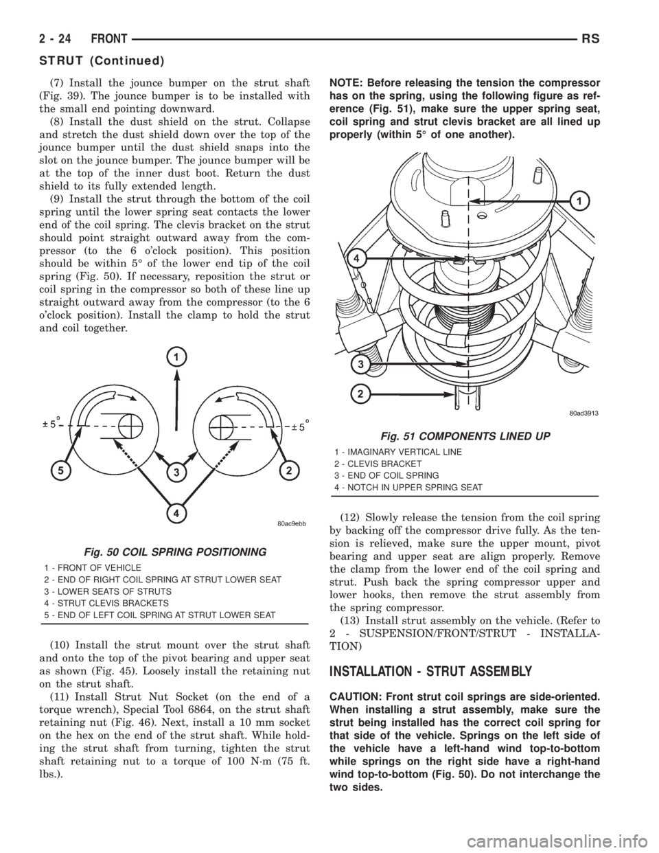
(9) Install the strut through the bottom of the coil
spring until the lower spring seat contacts the lower
end of the coil spring. The clevis bracket on the strut
should point straight outward away from the com-
pressor (to the 6 o'clock position). This position
should be within 5É of the lower end tip of the coil
spring (Fig. 50). If necessary, reposition the strut or
coil spring in the compressor so both of these line up
straight outward away from the compressor (to the 6
o'clock position). Install the clamp to hold the strut
and coil together.
(10) Install the strut mount over the strut shaft
and onto the top of the pivot bearing and upper seat
as shown (Fig. 45). Loosely install the retaining nut
on the strut shaft.
(11) Install Strut Nut Socket (on the end of a
torque wrench), Special Tool 6864, on the strut shaft
retaining nut (Fig. 46). Next, install a 10 mm socket
on the hex on the end of the strut shaft. While hold-
ing the strut shaft from turning, tighten the strut
shaft retaining nut to a torque of 100 N´m (75 ft.
lbs.).NOTE: Before releasing the tension the compressor
has on the spring, using the following figure as ref-
erence (Fig. 51), make sure the upper spring seat,
coil spring and strut clevis bracket are all lined up
properly (within 5É of one another).
(12) Slowly release the tension from the coil spring
by backing off the compressor drive fully. As the ten-
sion is relieved, make sure the upper mount, pivot
bearing and upper seat are align properly. Remove
the clamp from the lower end of the coil spring and
strut. Push back the spring compressor upper and
lower hooks, then remove the strut assembly from
the spring compressor.
(13) Install strut assembly on the vehicle. (Refer to
2 - SUSPENSION/FRONT/STRUT - INSTALLA-
TION)
INSTALLATION - STRUT ASSEMBLY
CAUTION: Front strut coil springs are side-oriented.
When installing a strut assembly, make sure the
strut being installed has the correct coil spring for
that side of the vehicle. Springs on the left side of
the vehicle have a left-hand wind top-to-bottom
while springs on the right side have a right-hand
wind top-to-bottom (Fig. 50). Do not interchange the
two sides.
Fig. 50 COIL SPRING POSITIONING
1 - FRONT OF VEHICLE
2 - END OF RIGHT COIL SPRING AT STRUT LOWER SEAT
3 - LOWER SEATS OF STRUTS
4 - STRUT CLEVIS BRACKETS
5 - END OF LEFT COIL SPRING AT STRUT LOWER SEAT
Fig. 51 COMPONENTS LINED UP
1 - IMAGINARY VERTICAL LINE
2 - CLEVIS BRACKET
3 - END OF COIL SPRING
4 - NOTCH IN UPPER SPRING SEAT
2 - 24 FRONTRS
STRUT (Continued)
Page 1541 of 4284
(1) Install strut assembly into strut tower, aligning
and installing the 3 studs on the upper strut mount
into the holes in shock tower. Install the 3 upper
strut mount attaching nut/washer assemblies (Fig.
44). Then using a crow foot. tighten the 3 attaching
nuts to a torque of 28 N´m (250 in. lbs.).
CAUTION: The steering knuckle to strut assembly
attaching bolts are serrated and must not be turned
during installation. Install nuts while holding bolts
stationary in the steering knuckles.
NOTE: The strut clevis-to-steering knuckle bolts are
installed differently on each side of the vehicle. Left
hand side bolts are to be installed from vehicle rear
to front. Right side bolts are to be installed from
vehicle front to rear.
(2) Align strut assembly with steering knuckle.
Position arm of steering knuckle into strut assembly
clevis bracket. Align the strut assembly clevis
bracket mounting holes with the steering knuckle
mounting holes. Install the 2 strut assembly to steer-
ing knuckle attaching bolts (Fig. 43).If strut assem-
bly is attached to steering knuckle using a cam
bolt, the cam bolt must be installed in the lower
slotted hole on strut clevis bracket.Tighten the
strut clevis-to-steering knuckle attaching bolts to atorque of 81 N´m (60 ft. lbs.) plus an additional 1/4
(90É) turn after specified torque is met.
(3) Install the stabilizer bar link mounting stud
through the bracket on the strut assembly (Fig. 42).
CAUTION: When installing the nut on the mounting
stud of the stabilizer bar link, do not allow the stud
to rotate in it's socket. Hold the stud from rotating
by placing an open-end wrench on the flat
machined into the stud (Fig. 42).
(4) Hand thread the nut on the end of the stabi-
lizer bar link stud. Hold the stud from turning by
placing an open-end wrench on the flat machined
into the link's mounting stud, then tighten the nut
while holding the wrench in place (Fig. 42). Tighten
the nut to a torque of 88 N´m (65 ft. lbs.).
(5) Install the hydraulic brake hose and speed sen-
sor cable routing brackets on the strut assembly
brackets (Fig. 41). Tighten the routing bracket
attaching bolts to a torque of 13 N´m (10 ft. lbs.).
(6) Install the wheel/tire assembly on the vehicle.
(7) Install and tighten the wheel mounting stud
nuts in proper sequence until all nuts are torqued to
half specification. Then repeat the tightening
sequence to the full specified torque of 135 N´m (100
ft. lbs.).
RSFRONT2-25
STRUT (Continued)
Page 1543 of 4284
SPECIFICATIONS
REAR SUSPENSION FASTENER TORQUE
DESCRIPTION N´mFt.
Lbs.In.
Lbs.
Hub And Bearing Mounting
Bolts129 95 Ð
Hub And Bearing Axle Hub Nut 244 180 Ð
Jounce Bumper Mounting Bolt 33 24 290
Leaf Spring Front Mount-To-
Body Bolts61 45 Ð
Leaf Spring Front Pivot Bolt 156 115 Ð
Leaf Spring Plate-To-Axle Bolts 102 75 Ð
Leaf Spring Rear Mount-To-
Body Bolts61 45 Ð
Leaf Spring Shackle Plate Nuts 61 45 Ð
Shock Absorber Mounting Bolts 102 75 Ð
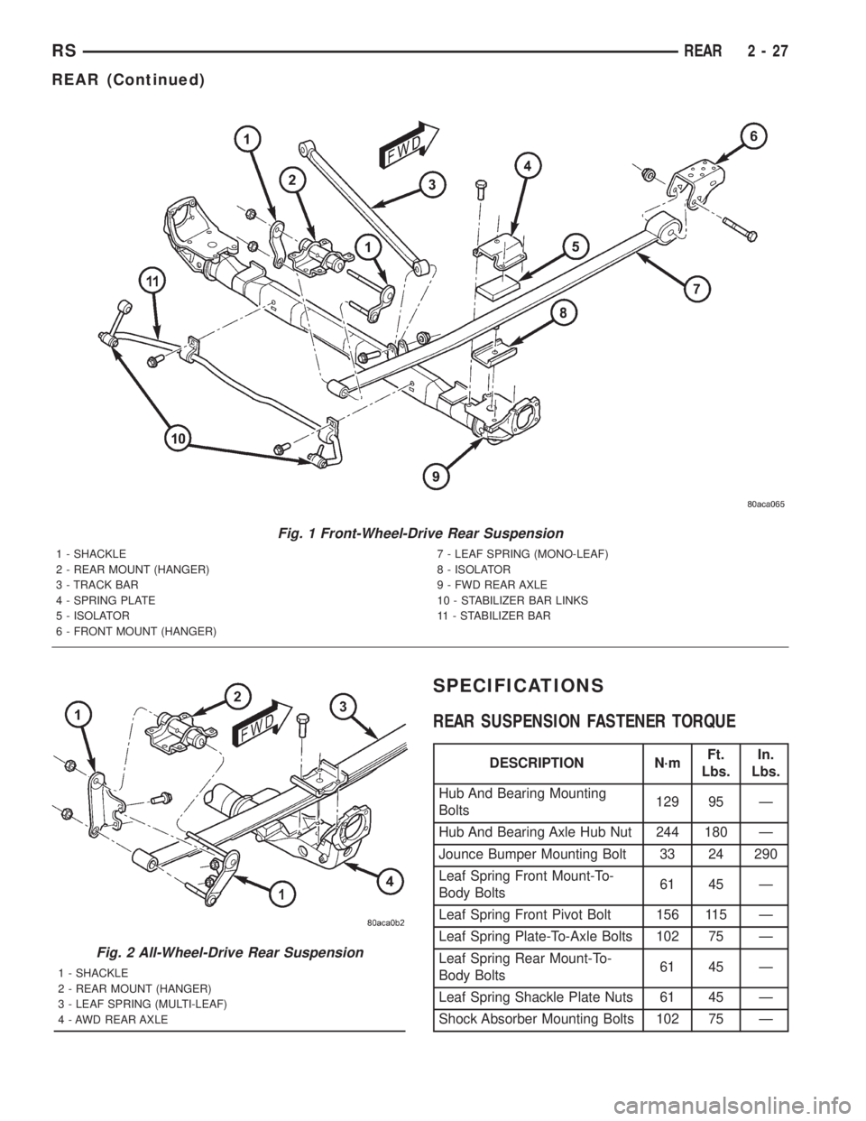
Fig. 1 Front-Wheel-Drive Rear Suspension
1 - SHACKLE
2 - REAR MOUNT (HANGER)
3 - TRACK BAR
4 - SPRING PLATE
5 - ISOLATOR
6 - FRONT MOUNT (HANGER)7 - LEAF SPRING (MONO-LEAF)
8 - ISOLATOR
9 - FWD REAR AXLE
10 - STABILIZER BAR LINKS
11 - STABILIZER BAR
Fig. 2 All-Wheel-Drive Rear Suspension
1 - SHACKLE
2 - REAR MOUNT (HANGER)
3 - LEAF SPRING (MULTI-LEAF)
4 - AWD REAR AXLE
RSREAR2-27
REAR (Continued)
Page 1546 of 4284
body, Install the mounting bolts (Fig. 3). Tighten the
four mounting bolts to 61 N´m (45 ft. lbs.) torque.
(9) Raise or lower the jack until shock absorber
lower eye aligns with threads in axle housing. Install
shock absorber lower mounting bolt. Do not fully
tighten bolt at this time.
(10) Lower the vehicle and remove hoist arms and
block of wood from under vehicle.
(11) Tighten the spring front pivot bolt to 156 N´m
(115 ft. lbs.) torque.
(12) Tighten the lower shock absorber mounting
bolt to 102 N´m (75 ft. lbs.) torque.
HUB / BEARING
DESCRIPTION
The rear wheel bearing and rear wheel hub of this
vehicle are a one-piece sealed unit, or hub and bear-
ing unit type assembly. The hub and bearing is
mounted to the center of the rear axle using 4
mounting bolts. It has five wheel mounting studs on
the hub flange.
All-Wheel-Drive vehicles have a hub and bearing
unit with a splined hole in the center of the hub for
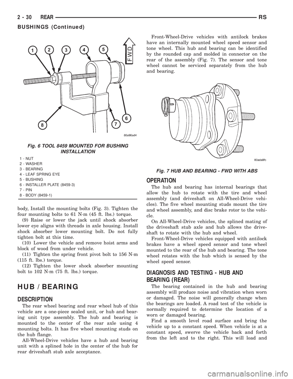
rear driveshaft stub axle acceptance.Front-Wheel-Drive vehicles with antilock brakes
have an internally mounted wheel speed sensor and
tone wheel. This hub and bearing can be identified
by the rounded cap and molded in connector on the
rear of the assembly (Fig. 7). The sensor and tone
wheel cannot be serviced separately from the hub
and bearing.
OPERATION
The hub and bearing has internal bearings that
allow the hub to rotate with the tire and wheel
assembly (and driveshaft on All-Wheel-Drive vehi-
cles). The five wheel mounting studs mount the tire
and wheel assembly, and disc brake rotor to the vehi-
cle.
On All-Wheel-Drive vehicles, the splined mating of
the driveshaft stub axle and hub allows the drive-
shaft to rotate with the hub and wheel.
Front-Wheel-Drive vehicles equipped with antilock
brakes have a wheel speed sensor and tone wheel
mounted to the rear of the hub and bearing. The tone
wheel rotates with the hub which is sensed by the
wheel speed sensor.
DIAGNOSIS AND TESTING - HUB AND
BEARING (REAR)
The bearing contained in the hub and bearing
assembly will produce noise and vibration when worn
or damaged. The noise will generally change when
the bearings are loaded. A road test of the vehicle is
normally required to determine the location of a
worn or damaged bearing.
Find a smooth level road surface and bring the
vehicle up to a constant speed. When vehicle is at a
constant speed, swerve the vehicle back and forth
from the left and to the right. This will load and
Fig. 6 TOOL 8459 MOUNTED FOR BUSHING
INSTALLATION
1 - NUT
2 - WASHER
3 - BEARING
4 - LEAF SPRING EYE
5 - BUSHING
6 - INSTALLER PLATE (8459-3)
7 - PIN
8 - BODY (8459-1)
Fig. 7 HUB AND BEARING - FWD WITH ABS
2 - 30 REARRS
BUSHINGS (Continued)
Page 1547 of 4284
unload the bearings and change the noise level.
When bearing damage is slight, the noise is usually
not noticeable at speeds above 48 km/h (30 mph).
REMOVAL - HUB AND BEARING
FRONT-WHEEL-DRIVE VEHICLES
(1) Raise vehicle. See Hoisting in Lubrication and
Maintenance.
(2) Remove wheel and tire.
(3) Remove brake drum or disc brake caliper and
rotor from hub and bearing. Refer to Brakes.
(4) If equipped with antilock brakes, perform the
following:
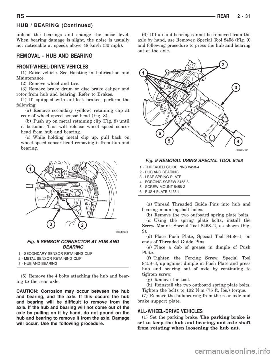
(a) Remove secondary (yellow) retaining clip at
rear of wheel speed sensor head (Fig. 8).
(b) Push up on metal retaining clip (Fig. 8) until
it bottoms. This will release wheel speed sensor
head from hub and bearing.
(c) While holding metal clip up, pull back on
wheel speed sensor head removing it from hub and
bearing.
(5) Remove the 4 bolts attaching the hub and bear-
ing to the rear axle.
CAUTION: Corrosion may occur between the hub
and bearing, and the axle. If this occurs the hub
and bearing will be difficult to remove from the
axle. If the hub and bearing will not come out of the
axle by pulling on it by hand, do not pound on the
hub and bearing to remove it from the axle. Damage
will occur. Use the following procedure.(6) If hub and bearing cannot be removed from the
axle by hand, use Remover, Special Tool 8458 (Fig. 9)
and following procedure to press the hub and bearing
out of the axle.
(a) Thread Threaded Guide Pins into hub and
bearing mounting bolt holes.
(b) Remove the two outboard spring plate bolts.
(c) Using the spring plate bolts, install the
Screw Mount, Special Tool 8458±2, as shown (Fig.
9).
(d) Place Push Plate, Special Tool 8458±1, on
ends of Threaded Guide Pins
(e) Place a dab of grease in dimple of Push
Plate.
(f) Tighten the Forcing Screw, Special Tool
8458±3, up against dimple in Push Plate and press
hub and bearing out of axle by continuing to
tighten screw.
(g) Remove the tool.
(h) Reinstall the two outboard spring plate bolts.
Tighten the bolts to 102 N´m (75 ft. lbs.) torque.
(7) Remove the hub/bearing from the rear axle and
brake support plate.
ALL-WHEEL-DRIVE VEHICLES
(1) Set the parking brake.The parking brake is
set to keep the hub and bearing, and axle shaft
from rotating when loosening the hub nut.
Fig. 8 SENSOR CONNECTOR AT HUB AND
BEARING
1 - SECONDARY SENSOR RETAINING CLIP
2 - METAL SENSOR RETAINING CLIP
3 - HUB AND BEARING
Fig. 9 REMOVAL USING SPECIAL TOOL 8458
1 - THREADED GUIDE PINS 8458-4
2 - HUB AND BEARING
3 - LEAF SPRING PLATE
4 - FORCING SCREW 8458-3
5 - SCREW MOUNT 8458-2
6 - PUSH PLATE 8458-1
RSREAR2-31
HUB / BEARING (Continued)
Page 1549 of 4284
INSTALLATION - HUB AND BEARING
FRONT-WHEEL-DRIVE VEHICLES
(1) Install the 4 hub and bearing to axle mounting
bolts into the holes in the flange of the rear axle.
(2) Install the rear brake support plate on the 4
mounting bolts installed in the flange of the rear
axle.
(3) Align the rear hub and bearing with the 4
mounting bolts and start mounting bolts into hub
and bearing. Tighten the 4 bolts in a crisscross pat-
tern until the hub nd bearing and brake support
plate is fully and squarely seated onto flange of rear
axle. Tighten the 4 mounting bolts to a torque of 129
N´m (95 ft. lbs.)
NOTE: If equipped with antilock brakes, make sure
wheel speed sensor stays clean and dry as it is
installed into the hub and bearing cap.
(4) If the vehicle is equipped with antilock brakes,
perform the following:
(a) If metal sensor retaining clip is not in the
neutral installed position on hub and bearing cap,
install from the bottom, if necessary, and push clip
upward until it snaps into position.
(b) Install wheel speed sensor head into rear of
hub and bearing aligning index tab with the notch
in the top of the mounting hole. Push the sensor in
until it snaps into place on the metal retaining
clip.
(c) Install secondary (yellow) retaining clip over
wheel speed sensor head and engage the tabs on
each side (Fig. 8).
(5) Install brake drum or disc brake rotor and
brake caliper. Refer to Brakes.
(6) Install wheel and tire. Tighten the wheel nuts
in the proper sequence to a torque of 135 N´m (100
ft. lbs.).
(7) Adjust the rear brakes as necessary. Refer to
Brakes.
(8) Lower vehicle.
(9) Road test vehicle to ensure proper operation of
brakes.
ALL-WHEEL-DRIVE VEHICLES
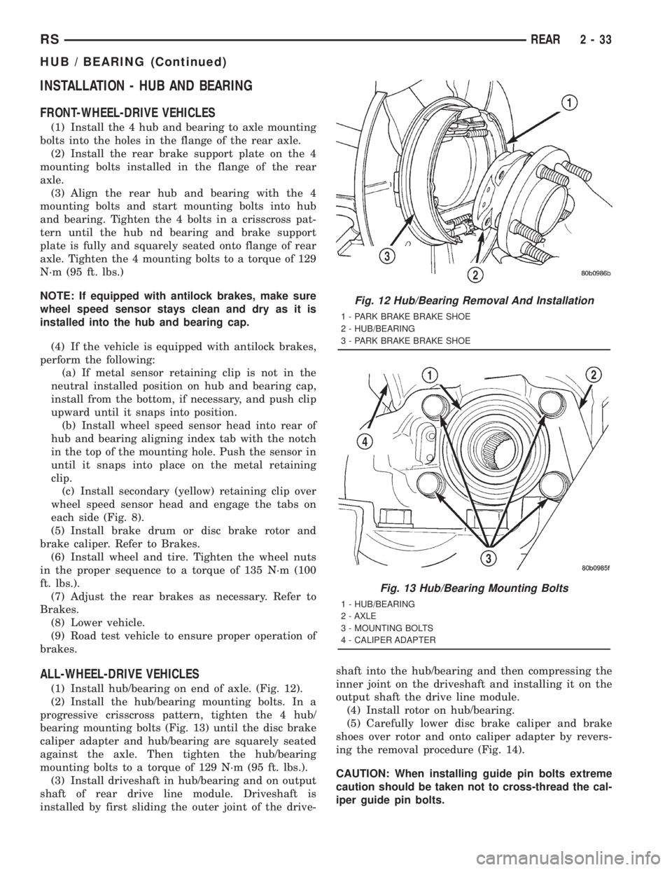
(1) Install hub/bearing on end of axle. (Fig. 12).
(2) Install the hub/bearing mounting bolts. In a
progressive crisscross pattern, tighten the 4 hub/
bearing mounting bolts (Fig. 13) until the disc brake
caliper adapter and hub/bearing are squarely seated
against the axle. Then tighten the hub/bearing
mounting bolts to a torque of 129 N´m (95 ft. lbs.).
(3) Install driveshaft in hub/bearing and on output
shaft of rear drive line module. Driveshaft is
installed by first sliding the outer joint of the drive-shaft into the hub/bearing and then compressing the
inner joint on the driveshaft and installing it on the
output shaft the drive line module.
(4) Install rotor on hub/bearing.
(5) Carefully lower disc brake caliper and brake
shoes over rotor and onto caliper adapter by revers-
ing the removal procedure (Fig. 14).
CAUTION: When installing guide pin bolts extreme
caution should be taken not to cross-thread the cal-
iper guide pin bolts.
Fig. 12 Hub/Bearing Removal And Installation
1 - PARK BRAKE BRAKE SHOE
2 - HUB/BEARING
3 - PARK BRAKE BRAKE SHOE
Fig. 13 Hub/Bearing Mounting Bolts
1 - HUB/BEARING
2 - AXLE
3 - MOUNTING BOLTS
4 - CALIPER ADAPTER
RSREAR2-33
HUB / BEARING (Continued)
Page 1550 of 4284
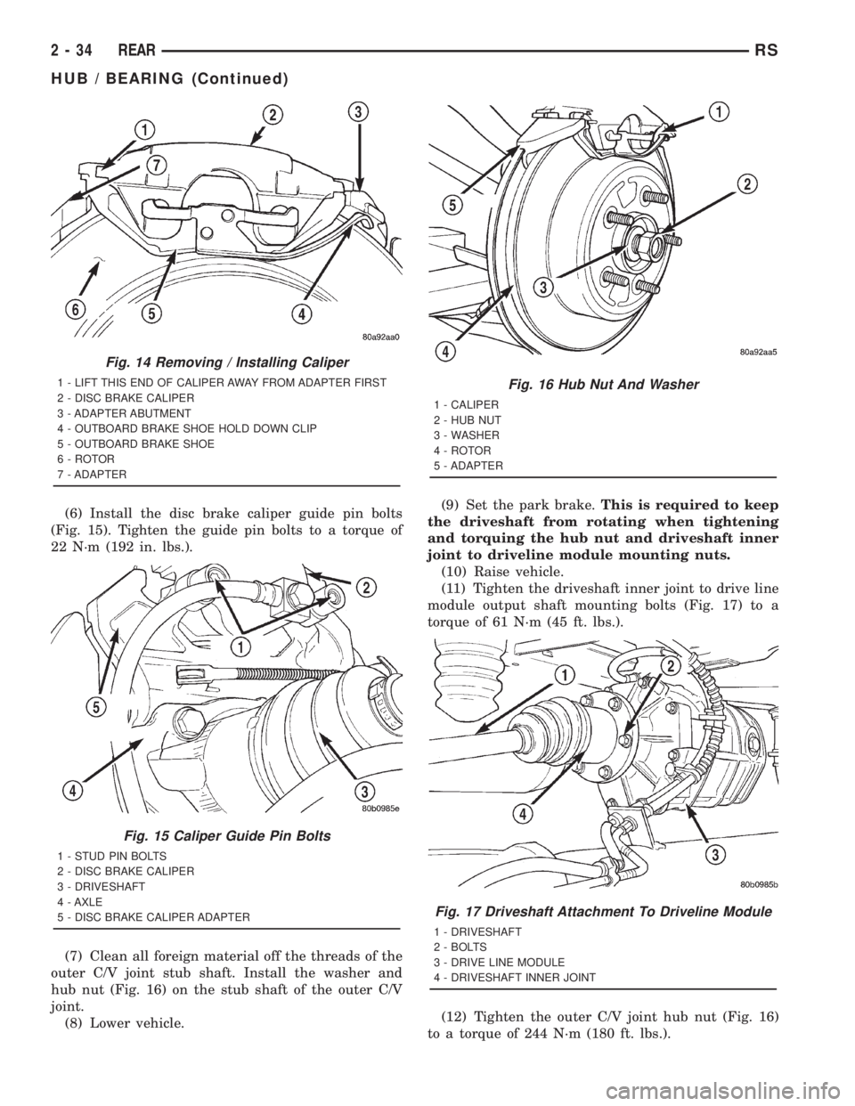
(6) Install the disc brake caliper guide pin bolts
(Fig. 15). Tighten the guide pin bolts to a torque of
22 N´m (192 in. lbs.).
(7) Clean all foreign material off the threads of the
outer C/V joint stub shaft. Install the washer and
hub nut (Fig. 16) on the stub shaft of the outer C/V
joint.
(8) Lower vehicle.(9) Set the park brake.This is required to keep
the driveshaft from rotating when tightening
and torquing the hub nut and driveshaft inner
joint to driveline module mounting nuts.
(10) Raise vehicle.
(11) Tighten the driveshaft inner joint to drive line
module output shaft mounting bolts (Fig. 17) to a
torque of 61 N´m (45 ft. lbs.).
(12) Tighten the outer C/V joint hub nut (Fig. 16)
to a torque of 244 N´m (180 ft. lbs.).
Fig. 14 Removing / Installing Caliper
1 - LIFT THIS END OF CALIPER AWAY FROM ADAPTER FIRST
2 - DISC BRAKE CALIPER
3 - ADAPTER ABUTMENT
4 - OUTBOARD BRAKE SHOE HOLD DOWN CLIP
5 - OUTBOARD BRAKE SHOE
6 - ROTOR
7 - ADAPTER
Fig. 15 Caliper Guide Pin Bolts
1 - STUD PIN BOLTS
2 - DISC BRAKE CALIPER
3 - DRIVESHAFT
4 - AXLE
5 - DISC BRAKE CALIPER ADAPTER
Fig. 16 Hub Nut And Washer
1 - CALIPER
2 - HUB NUT
3 - WASHER
4 - ROTOR
5 - ADAPTER
Fig. 17 Driveshaft Attachment To Driveline Module
1 - DRIVESHAFT
2 - BOLTS
3 - DRIVE LINE MODULE
4 - DRIVESHAFT INNER JOINT
2 - 34 REARRS
HUB / BEARING (Continued)
Page 1551 of 4284
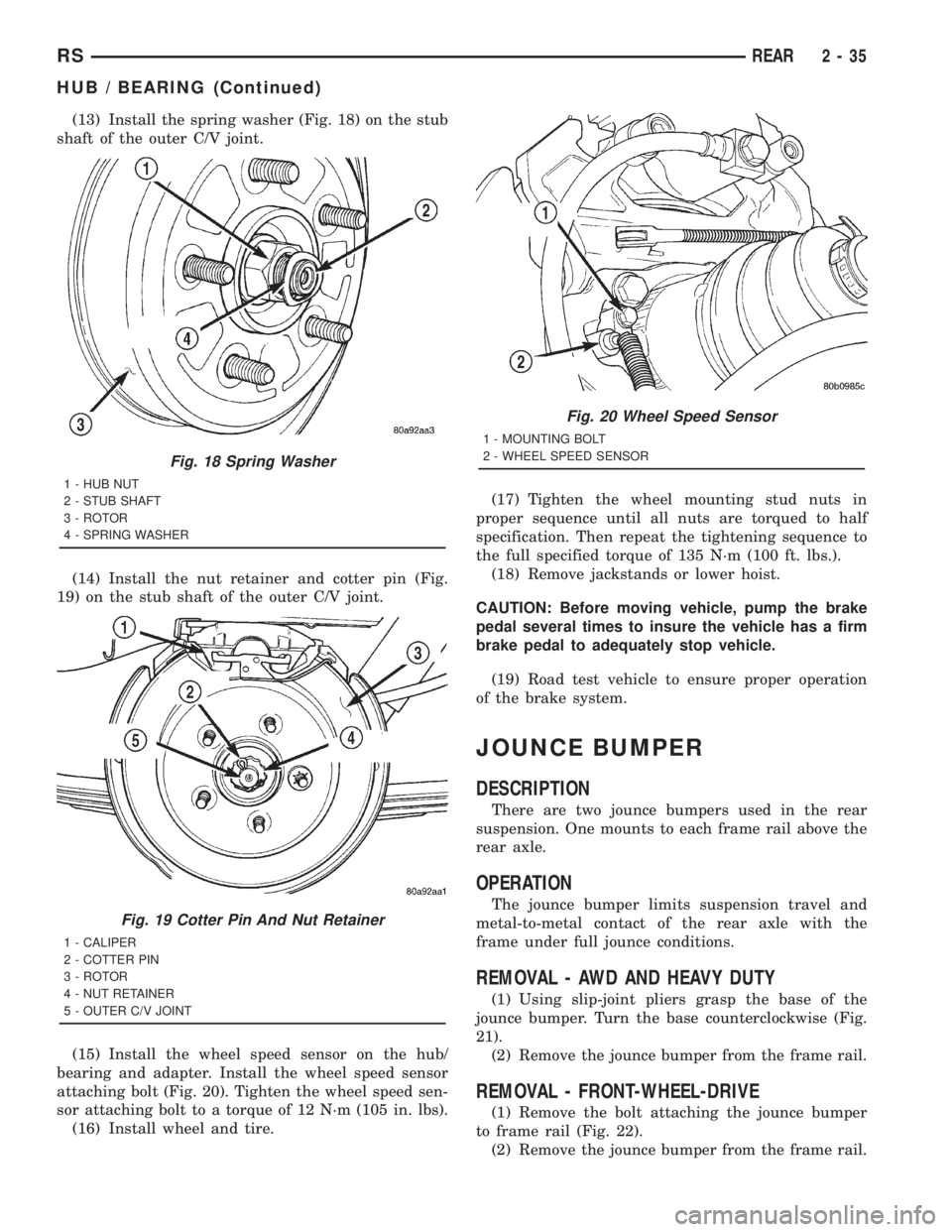
(13) Install the spring washer (Fig. 18) on the stub
shaft of the outer C/V joint.
(14) Install the nut retainer and cotter pin (Fig.
19) on the stub shaft of the outer C/V joint.
(15) Install the wheel speed sensor on the hub/
bearing and adapter. Install the wheel speed sensor
attaching bolt (Fig. 20). Tighten the wheel speed sen-
sor attaching bolt to a torque of 12 N´m (105 in. lbs).
(16) Install wheel and tire.(17) Tighten the wheel mounting stud nuts in
proper sequence until all nuts are torqued to half
specification. Then repeat the tightening sequence to
the full specified torque of 135 N´m (100 ft. lbs.).
(18) Remove jackstands or lower hoist.
CAUTION: Before moving vehicle, pump the brake
pedal several times to insure the vehicle has a firm
brake pedal to adequately stop vehicle.
(19) Road test vehicle to ensure proper operation
of the brake system.
JOUNCE BUMPER
DESCRIPTION
There are two jounce bumpers used in the rear
suspension. One mounts to each frame rail above the
rear axle.
OPERATION
The jounce bumper limits suspension travel and
metal-to-metal contact of the rear axle with the
frame under full jounce conditions.
REMOVAL - AWD AND HEAVY DUTY
(1) Using slip-joint pliers grasp the base of the
jounce bumper. Turn the base counterclockwise (Fig.
21).
(2) Remove the jounce bumper from the frame rail.
REMOVAL - FRONT-WHEEL-DRIVE
(1) Remove the bolt attaching the jounce bumper
to frame rail (Fig. 22).
(2) Remove the jounce bumper from the frame rail.
Fig. 18 Spring Washer
1 - HUB NUT
2 - STUB SHAFT
3 - ROTOR
4 - SPRING WASHER
Fig. 19 Cotter Pin And Nut Retainer
1 - CALIPER
2 - COTTER PIN
3 - ROTOR
4 - NUT RETAINER
5 - OUTER C/V JOINT
Fig. 20 Wheel Speed Sensor
1 - MOUNTING BOLT
2 - WHEEL SPEED SENSOR
RSREAR2-35
HUB / BEARING (Continued)