2001 CHRYSLER VOYAGER power steering
[x] Cancel search: power steeringPage 31 of 4284
mitted on the bus even though a module may not
require all information to perform its function. It
will only respond to messages ªaddressedº to it
through binary coding process. This method of data
transmission significantly reduces the complexity
of the wiring in the vehicle and the size of wiring
harnesses. All of the information about the func-
tioning of all the systems is organized, controlled,
and communicated by the PCI bus, which is de-
scribed in the Communication Section of this gen-
eral information.
3.1 AIRBAG SYSTEM/OCCUPANT
RESTRAINT CONTROLLER SYSTEM
The 2001 Minivan Airbag System contain the
following components: Occupant Restraint Control-
ler (ORC), Airbag Warning Indicator, Clockspring,
Driver and Passenger Airbags, Seat belt Tensioners
(SBT), Hall-effect Seat Belt Switches (SBS), Left
and Right Side Airbag Control Module (SIACM),
and Seat (mounted side) Airbags.
The Occupant Restraint Controller (ORC) is a
new type of Airbag Control Module (ACM) that
supports staged airbag deployment. Staged deploy-
ment is the ability to trigger airbag system squib
inflators all at once or individually as needed to
provide the appropriate restraint for the severity of
the impact. The ORC has four major functions: PCI
Bus communications, onboard diagnostics, impact
sensing, and component deployment. The ORC also
contains an energy-storage capacitor. This capaci-
tor stores enough electrical energy to deploy the
front airbag components for two seconds following a
battery disconnect or failure during an impact. The
ORC is secured to the floor panel transmission
tunnel below the instrument panel inside the vehi-
cle. The ORC cannot be repaired or adjusted and
must be replaced.
The ORC sends and/or receives PCI Bus mes-
sages with the Instrument Cluster (MIC), Body
Control Module (BCM), and Powertrain Control
Module (PCM). Diagnostic trouble codes will be set
if the communication with these modules is lost or
contains invalid information.
The microprocessor in the ORC monitors the
impact sensor signal and the airbag system electri-
cal circuits to determine the system readiness. The
ORC also monitors bus messages from both SIACM.
If the ORC detects a monitored system fault or
SIACM fault, it sends a message to the instrument
cluster via PCI bus to turn on the airbag warning
indicator. The ORC can set both active and stored
diagnostic trouble codes to aid in the diagnosing
system problems. See ORC/SIACM DIAGNOSTIC
TROUBLE CODES in this section.
The ORC has an internal accelerometer that
senses the rate of vehicle deceleration, which pro-vides verification of the direction and severity of an
impact. A pre-programmed decision algorithm in
the ORC microprocessor determines when the de-
celeration rate is severe enough to require airbag
system protection. The Occupant Restraint Control-
ler (ORC) also uses the driver and front passenger
seat belt switch status (buckled or unbuckled) as
inputs to determine the level of airbag deployment,
low, medium, or high as well as whether or not the
seat belt tensioners should deploy. The ORC also
uses the crash severity to determine the level of
driver and front passenger deployment, low me-
dium or high. When the programmed conditions are
met, the ORC sends an electrical signal to deploy
the appropriate airbag system components.WARNING: THE AIRBAG SYSTEM IS A
SENSITIVE, COMPLEX ELECTRO-
MECHANICAL UNIT. BEFORE ATTEMPTING
TO DIAGNOSE OR SERVICE ANY AIRBAG
SYSTEM OR RELATED STEERING WHEEL,
STEERING COLUMN, OR INSTRUMENT
PANEL COMPONENTS YOU MUST FIRST
DISCONNECT AND ISOLATE THE BATTERY
NEGATIVE (GROUND) CABLE. WAIT TWO
MINUTES FOR THE SYSTEM CAPACITOR TO
DISCHARGE BEFORE FURTHER SYSTEM
SERVICE. THIS IS THE ONLY SURE WAY TO
DISABLE THE AIRBAG SYSTEM. FAILURE
TO DO THIS COULD RESULT IS ACCIDENTAL
AIRBAG DEPLOYMENT AND POSSIBLE
PERSONAL INJURY. NEVER STRIKE OR
KICK THE AIRBAG CONTROL MODULE, AS
IT CAN DAMAGE THE IMPACT SENSOR OR
AFFECT ITS CALIBRATION. IF AN AIRBAG
CONTROL MODULE IS ACCIDENTALLY
DROPPED DURING SERVICE, THE MODULE
MUST BE SCRAPPED AND REPLACED WITH
A NEW UNIT.
The airbag warning lamp is the only point at
which the customer can observe symptoms of a
system malfunction. Whenever the ignition key is
turned to the run or start position, the MIC per-
forms a lamp check by turning the airbag warning
indicator on for 6-8 seconds. After the lamp check, if
the indicator turns on, it means that the ORC has
checked the system and found it to be free of
discernible malfunctions. If the lamp remains on,
there could be an active fault in the system or the
MIC lamp circuit may be internally shorted to
ground. If the lamp comes on and stays on for a
period longer than 6-8 seconds then goes off, there
is usually an intermittent problem in the system.
2
GENERAL INFORMATION
Page 37 of 4284
this type of system would only refer to this circuit.
A faulty speaker could not cause this DTC.
3.2.1 REMOTE RADIO CONTROLS
These radios can be controlled via remote radio
switches (optional). These switches are located on
the back side of the steering wheel. They control
mode, preset, seek up, seek down, volume up and
volume down functions.
These functions are inputs to the Body Control
Module and can be read with the DRBIIItunder
ªbody computerº. The switches are a multiplexed
signal to the BCM. The radio control MUX circuit is
a 5 volt line that is pulled to ground through
different value resistors built into the switches.
This causes a voltage drop to be seen by the BCM
and it sends a specific message to the radio on the
PCI Bus circuit. The radio then responses to the
message.
This circuit is fairly simple to troubleshoot. The
circuit must be complete from the switches in the
steering wheel to the BCM. The ground must be
complete so that the switches can cause the voltage
drop for the BCM to see. The circuit passes through
the clockspring so continuity through this devise
must be verified.
3.2.2 CD CHANGER
The new in-dash CD Changer is designed to fit
into the existing cubby bin in the center stack. This
new cartridge-less CD Changer is controlled by
your radio, and allows you to individually load up to
four discs at a time. However, due to its compact
design, the CD Changer can only carry out one
operation at a time. For example, you can not load
a new disc while playing another at the same time.
Each operation happens sequentially.
The radio unit installed with your system pro-
vides control over all features of the CD Changer
with the exception of the CD load and eject func-
tions, which are controlled by buttons located on the
front of the CD Changer. The radio also supplies the
power, ground, PCI Bus, left and right speaker
output thru a single DIN cable. All features you
would expect, such as Disc Up/Down, Track Up/
Down, Random and Scan are controlled by the
radio, which also displays all relevant CD Changer
information on the radio display.
The CD Changer contains a Load/Eject button
and an indicator light for each of the four disc
positions. The individual light indicates whether a
CD is currently loaded in that particular chamber of
the CD Changer. Pressing the individual Load/Eject
button for a particular chamber will eject a disc
currently present in that chamber. If the chamber iscurrently empty, actuating the Load/Eject button
will position that chamber to receive and load a new
disc in that chamber.
3.3 BODY CONTROL MODULE
The body control module (BCM) supplies vehicle
occupants with visual and audible information and
controls various vehicle functions. To provide and
receive information, the module is interfaced to the
vehicle's serial bus communications network (PCI).
This network consists of the powertrain control
module (PCM), the engine control module (ECM) -
diesel only, the transmission control module (TCM),
the mechanical instrument cluster (MIC), the front
control module (FCM), the occupant restraint con-
troller (ORC), the compass/mini-trip (CMTC), the
electronic vehicle information center (EVIC), the
controller antilock brake (CAB), the HVAC control
module (ATC & MTC), the power sliding door (Left
& Right) modules (PSD), the power liftgate module
(PLG), the Audio system, the side impact airbag
control (left & right) modules (SIACM), the memory
seat/mirror module (MSMM), the RKE/thatcham
alarm module and the sentry key immobilizer mod-
ule (SKIM). The BCM is operational when battery
power is supplied to the module.
The body control module provides the following
features:
²Power Door Locks
²Automatic Door Lock
²Door Lock Inhibit
²Central Locking (with VTSS Only)
²Battery Protection
²The BCM will automatically turn off all exterior
lamps after 3 minutes and all interior lamps after
15 minutes after the ignition is turned off, if they
are not turned off by the driver.
²Chime
²Compass/Minitrip Support
²Interior Lighting (Courtesy/Reading Lamps)
²BCM Diagnostic Reporting
²Electronic Liftgate Release (with Power Door
Locks)
²Exterior Lighting
²Power Folding Mirrors
²Remote Radio Controls
²Headlamp Time Delay (with/without Autohead-
lamps)
²Automatic Headlamps (with electrochromatic
mirror)
²Illuminated Entry
²Fade to Off
8
GENERAL INFORMATION
Page 53 of 4284

seconds instead of 5, the CMTC will set the
variance to 8 and enter the fast calibration
mode.
3. The VAR light will come on and the last variance
setting will be displayed.
4. Press the STEP button to set the zone number.
5. Press the US/M button and resume normal op-
eration.
NOTE: Do not attach any magnetic device
such as a magnetic CB antenna to the
vehicle. This can cause the compass to give
false readings.
3.15 POWER DOOR LOCK SYSTEM
When the BCM receives input for a lock request
from a door lock switch, RKE or cylinder lock switch
(only with VTSS), it will turn the lock driver on for
a specified time of 375 msec. If the request is there
beyond 375 msec, the BCM considers the door lock
signal stuck. Once a door lock or unlock signal is
stuck for longer than 10 seconds, the BCM will set
a trouble code and the signal input is ignored until
the stuck condition disappears. The door lock
switches provide a variable amount of resistance
thereby dropping the voltage of the multiplexed
(MUX) circuit and the BCM will respond to that
command.
3.15.1 SLIDING DOOR MEMORY LOCK
When the BCM receives an input for a lock
request and a sliding door is open, the BCM will
turn on the lock driver as described above, and will
turn it on again when all sliding doors are closed.
NOTE: If the BCM receives an unlock input before
a sliding door is closed, this will cancel the memory
lock.
3.15.2 DOOR LOCK INHIBIT
When the key is in the ignition and in any
position and either front door is open, the door lock
switches LOCK functions are disabled. The UN-
LOCK functions are still functional. This protects
against locking the vehicle with the keys still in the
ignition. The RKE key fob will still lock the doors as
usual. This allows the driver to lock the vehicle with
the engine running for warm up.
3.15.3 AUTOMATIC DOOR LOCKS
This feature can be enabled or disabled by using
either the DRBIIItor the customer programming
method. When enabled all the doors will lock when
the vehicle reaches a speed of 18 MPH (29 KMH)
and all the doors are closed. If a door is opened and
the vehicle slows to below 18 MPH (29 KMH), thedoor locks will operate again once all doors are
closed and the speed is above 15 MPH (24 KMH).
3.15.4 REMOTE KEYLESS ENTRY (RKE)
The body control module interfaces with the RKE
module via a one-way serial bus interface. The RKE
module is not on the PCI bus. The RKE module
sends a 0-5 volt pulse width signal to the BCM
depending on which button on the transmitter was
pressed. The BCM controls the door lock/unlock
functions and the arming/disarming of the Vehicle
Theft Security System (if equipped) and the activa-
tion of illuminated entry. The BCM will also send
the appropriate messages to the Power Sliding
Doors and Power Liftgate modules. The Intelligent
Power Module (IPM) activates the park lamps,
headlamps, and horn for horn chirp when sent the
appropriate message from the BCM as received
from the RKE transmitter. When a one-button
press is made for unlock, both driver side doors will
unlock and the front and rear turn signal will flash.
When a second press is initiated (within 5 seconds
of the first) both passenger doors will unlock and all
four turn signals will flash.
The RKE module is capable of retaining up to 4
individual access codes (4 transmitters). If the
PRNDL is in any position except park, the BCM will
ground the interface thereby disabling the RKE.
The 2 button transmitter will have 2-CR2016
batteries in series. The 5 button transmitter will
have 1-CR2016 battery. The minimum battery life
should be approximately 4.7 years based on 20
transmissions a day at 84ÉF (25ÉC). Using the
DRBIIItand selecting RKE FOB Test can test the
transmitter.
The RKE module can be programmed via the
DRBIIItor the customer programming method.
The BCM will only allow programming mode to be
entered when the ignition is in the on position, the
PRNDL is in park position, and the VTSS (if
equipped) is in the disarmed mode.
3.16 POWER FOLDING MIRRORS
The power folding mirrors are powered to two
positions: folded and unfolded. The driver may
choose fold or unfold with a switch that is located on
the right side of the steering column. The folding
mirror switch grounds a sense wire that comes from
the Body Control Module when it is placed in the
fold position. The mirrors will move to the position
designated by the switch whether the ignition
switch is the On or Off position and both front doors
are closed. When the Power Folding Mirror switch
is left in the fold position during a vehicle exit the
mirrors will automatically unfold then refold after
both front doors are closed. This is to prevent mirror
contact with either front door when opened. When
24
GENERAL INFORMATION
Page 1160 of 4284
²three power feeds: valves, pump and microproces-
sor
²brake switch
²traction control switch
The CAB outputs include the following:
²ABS warning indicator actuation
²12 volts power to wheel speed sensors
²eight valves
²ten valves with traction control
²diagnostic communication
²PCI bus communication
²traction control lamp illumination
3.3.3 HYDRAULIC CONTROL UNIT
The hydraulic control unit (HCU) contains the
valve block assembly, two accumulators, and pump/
motor assembly. The HCU is attached to the CAB.
Valve Block Assembly:The valve block assem-
bly contains valves with four inlet valves and four
outlet valves. The inlet valves are spring-loaded in
the open position and the outlet valves are spring
loaded in the closed position. During an antilock
stop, these valves are cycled to maintain the proper
slip ratio for each wheel. If a wheel detects slip, the
inlet valve is closed to prevent and further pressure
increase. Then the outlet valve is opened to release
the pressure to the accumulators until the wheel is
no longer slipping. Once the wheel is no longer
slipping, the outlet valve is closed and the inlet
valve is opened to reapply pressure. If the wheel is
decelerating within its predetermined limits (prop-
er slip ratio), the inlet valve will close to hold the
pressure constant. On vehicles which are equipped
with a traction control system, there are two addi-
tional valves that isolate the master cylinder and
rear wheels. During a traction control event the
brakes are applied to reduce wheel slippage.
Pump Motor Assembly:The pump motor as-
sembly provides the extra amount of fluid needed
during antilock braking. The pump is supplied fluid
that is released to the accumulators when the outlet
valve is opened during an antilock stop. The pump
is also used to drain the accumulator circuits after
the antilock stop is complete. The pump is operated
by an integral electric motor. This DC-type motor is
controlled by the CAB. The CAB may turn on the
pump motor when an antilock stop is detected. The
pump continues to run during the antilock stop and
is turned off after the stop is complete. Under some
conditions, the pump motor will run to drain the
accumulators during the next drive off. The CAB
monitors the pump motor operation internally.
Accumulators:The accumulators provide tem-
porary fluid storage during an antilock stop and are
drained by the pump motor.
3.3.4 SWITCHES/SENSORS
Master Cylinder:The master cylinder is a stan-
dard tandem compensating port design for ABS and
non ABS systems. Traction control vehicles use a
dual center port master cylinder. For proper trac-
tion control operation the standard master cylinder
must not be used.
A fluid level switch is located in the master
cylinder fluid reservoir. The switch closes when a
low fluid level is detected. The fluid level switch
turns on the brake warning indicator by grounding
the indicator circuit. This switch does not disable
the ABS system.
Wheel Speed Sensors and Tone Wheels:One
active wheel speed sensor (WSS) is located at each
wheel and sends a small signal to the control
module (CAB). This signal is generated when a
toothed sensor ring (tone wheel) passes by a station-
ary wheel speed sensor. The CAB converts the
signals into digital signals for each wheel.
Because of internal circuitry, correct wheel speed
sensor function cannot be determined by a continu-
ity or resistance check through the sensor.
The front wheel speed sensor is attached to a boss
in the steering knuckle. The tone wheel is an
integral part of the front axle shaft. The rear speed
sensor is mounted though the bearing cover and the
rear tone wheel is an integral part of the rear
bearing hub. The wheel speed sensor air gap is not
adjustable. Refer to the service manual for wheel
speed sensor air gap and resistance specifications.
The four wheel speed sensors are serviced indi-
vidually. The front tone wheels are serviced as an
assembly with the outer constant velocity (C.V.)
joint housing. The rear tone wheels are serviced as
an assembly.
Correct antilock system operation is dependent
on tone wheel speed signals from the wheel speed
sensors. The vehicle's wheels and tires should all be
the same size and type to generate accurate signals.
In addition, the tires should be inflated to the
recommended pressure for optimum system opera-
tion. Variation in wheel and tire size or significant
variations in inflation pressure can produce inaccu-
rate wheel speed signals; however, the system will
continue to function when using the mini-spare.
3.3.5 SYSTEM INITIALIZATION
System initialization starts when the key is
turned to ªrunº. At this point, the CAB performs a
complete self-check of all electrical components in
the antilock systems.
Between 8-17 km/h (5-10 mph), a dynamic test is
performed. This will momentarily cycle the inlet
and outlet valves, check wheel speed sensor cir-
cuitry, and run the pump motor at 25 km/h (15
mph). The CAB will try to test the pump motor. If
3
GENERAL INFORMATION
Page 1163 of 4284
4.3 WARNINGS
4.3.1 VEHICLE DAMAGE WARNINGS
Before disconnecting any control module, make
sure the ignition is ``off ''. Failure to do so could
damage the module.
When testing voltage or continuity at any control
module, use the terminal side (not the wire end) of
the connector. Do not probe a wire through the
insulation, this will damage it and eventually cause
it to fail because of corrosion.
Be careful when performing electrical tests so as
to prevent accidental shorting of terminals. Such
mistakes can damage fuses or components. Also, a
second code could be set, making diagnosis of the
original problem more difficult.
4.3.2 ROAD TESTING A COMPLAINT
VEHICLE
Some complaints will require a test drive as part
of the repair verification procedure. The purpose of
the test drive is to try to duplicate the diagnostic
code or symptom condition.
WARNING: BEFORE ROAD TESTING A
VEHICLE, BE SURE THAT ALL
COMPONENTS ARE REASSEMBLED.
DURING THE TEST DRIVE, DO NOT TRY TO
READ THE DRB SCREEN WHILE IN MOTION.
DO NOT HANG THE DRBIIITFROM THE
REAR VIEW MIRROR OR OPERATE IT
YOURSELF. HAVE AN ASSISTANT
AVAILABLE TO OPERATE THE DRBIIIT.
4.4 DIAGNOSIS
1. Your diagnostic test procedure must begin with a
thorough visual inspection of the ABS system for
damaged components or disconnected connec-
tors. The brake lamps must be operational, and
if they are not, repair them prior to continuing.
2. Connect the DRBIIItto the data link connector,
which is located under the dash to the left of the
steering column. If the DRBIIItdoes not power
up, check the power and ground supplies to the
connector.
3. Turn the ignition on. Select ªAntilock Brakesº. If
the DRBIIItdisplays ªNo Responseº condition
you must diagnose that first.
4. Read and record all ABS diagnostic trouble
codes. If the ªCAB Power Feed Circuitº diagnos-
tic trouble code is present, it must be repaired
prior to addressing any other DTC's. If any
additional DTC's are present, proceed to theappropriate test by locating the matching test in
the Table of Contents and begin to diagnose the
symptom.
5. If there are no diagnostic trouble codes present,
identify the customer complaint. Select ªInputs/
Outputsº and read the brake switch input as you
press and release the brake pedal. If the display
does not match the state of the pedal, perform
the proper test by locating the matching test in
the Table of Contents and begin to diagnose the
symptom. If a problem exists with the yellow
ªABSº warning indicator or the red ªBrakeº
indicator exists, refer to the proper tests by
locating the matching test in the Table of Con-
tents and begin to diagnose the symptom. Read
the traction control switch input as you press
and release the switch. If the display does not
match the state of the indicator perform the
proper test by locating the matching test in the
Table of Contents and begin to diagnose the
symptom.
6. If no other problems are found, it will be neces-
sary to road test the vehicle. Perform several
antilock stops from above 50 Km/h (30 mph) and
then repeat step 4. If any diagnostic trouble
codes are present, proceed to the appropriate test.
7. The following conditions should be considered
ªNORMALº operation, and no repairs should be
attempted to correct them.
± Brake pedal feedback during an ABS stop
(clicking, vibrating).
± Clicking, groaning or buzzing at 25 Km/h (15
mph) or 40 Km/h (24 mph) (drive off self test).
± Groaning noise during an ABS stop.
± Slight brake pedal drop and pop noise when
ignition is initially turned on.
± Brake pedal ratcheting down at the end of an
ABS stop.
8. If the complaint is ABS ªcyclingº at the end of a
stop at low speeds, it may be caused by a
marginal wheel speed sensor signal. The sensor
air gap, tone wheel condition, and/or brakes
hanging up are possible causes of this condition.
9. After a road test in which no problems were
found, refer to any Technical Service Bulletins
that may apply.
5.0 REQUIRED TOOLS AND
EQUIPMENT
DRBIIIt(diagnostic read-out box)
jumper wires
ohmmeter
voltmeter
test light
6
GENERAL INFORMATION
Page 1220 of 4284
1.0 INTRODUCTION
The procedures contained in this manual include
all the specifications, instructions and graphics
needed to diagnose engine control module (ECM)
and sentry key immobilizer system (SKIS) prob-
lems; they are no start, diagnostic trouble code
(DTC), and no trouble code problems for the ECM.
The diagnostics in this manual are based on the
trouble condition or symptom being present at the
time of diagnosis.
When repairs are required, refer to the appropri-
ate service information for the proper removal and
repair procedure.
Diagnostic procedures change every year. New
diagnostic systems may be added; carryover sys-
tems may be enhanced. IT IS RECOMMENDED
THAT YOU REVIEW THE ENTIRE MANUAL TO
BECOME FAMILIAR WITH ALL NEW AND
CHANGED DIAGNOSTIC PROCEDURES.
This manual is designed to begin all diagnosis at
the DTC TEST, which is located at the beginning of
Section 7.0. This will cover all the necessary re-
quirements to begin a logical diagnostic path for
each problem. If there is a diagnostic trouble code
(DTC) detected, it will direct you to the trouble code
test. If there are no DTCs present, it will direct you
by symptom to a no trouble code test.
This book reflects many suggested changes from
readers of past issues. After using this book, if you
have any comments or recommendations, please fill
out the form at the back of the book and mail it back
to us.
1.1 SYSTEM COVERAGE
This diagnostic procedures manual covers all
2001 RG body vehicles equipped with the 2.5L VM
diesel engine.
1.2 SIX-STEP TROUBLESHOOTING
PROCEDURE
Diagnosis of the engine control module (ECM)
and sentry key immobilizer system (SKIS) is done
in six basic steps:
²verification of complaint
²verification of any related symptom
²symptom analysis
²problem isolation
²repair of isolated problem
²verification of proper operation
NOTE: All tests in this manual should be per-
formed with the engine at operating temperature,
unless specified within a particular test.
2.0 IDENTIFICATION OF
SYSTEM
The ECM is located in the left side of the engine
compartment between the left front headlamp and
the intelligent power module. The sentry key immo-
bilizer module (SKIM) is located below the steering
column behind the steering wheel.
3.0 SYSTEM DESCRIPTION AND
FUNCTIONAL OPERATION
3.1 GENERAL DESCRIPTION
The 2.5L VM diesel engine system is equipped
with the latest in technical advances. The on-board
diagnostics incorporated in the engine control mod-
ule and SKIM are intended to assist the field
technician in repairing vehicle problems by the
quickest means.
The engine system incorporates a common rail
fuel delivery design. This design utilizes electroni-
cally controlled solenoid valve type fuel injectors.
Each injector is controlled individually by the ECM.
Injector timing and fuel quantity are controlled by
the ECM based on inputs from the various sensors.
The precision control of the injectors by the ECM
helps to reduce the engine noise, odor and smoke.
3.2 FUNCTIONAL OPERATION
3.2.1 ECM ON-BOARD DIAGNOSTICS
The ECM has been programmed to monitor many
different circuits of the diesel fuel injection system.
This monitoring is called on-board diagnostics.
Certain criteria must be met for a trouble code to
be entered into the ECM memory. The criteria may
be a range of: engine rpm, engine temperature, time
or other input signals to the ECM. If all of the
criteria for monitoring a system or circuit are met,
and a problem is sensed, then a DTC will be stored
in the ECM memory.
It is possible that a DTC for a monitored circuit
may not be entered into the ECM memory, even
though a malfunction has occurred. This may hap-
pen when the monitoring criteria has not been met.
The ECM compares input signal voltages from
each input device with specifications (the estab-
lished high and low limits of the input range) that
are programmed into it for that device. If the input
voltage is not within the specifications and other
trouble code criteria are met, a DTC will be stored
in the ECM memory.
1
GENERAL INFORMATION
Page 1468 of 4284
GROUP TAB LOCATOR
INIntroduction
INaIntroduction
0Lubrication & Maintenance
0aLubrication & Maintenance
2Suspension
2aSuspension
3Differential & Driveline
5Brakes
5aBrakes
6aClutch
7Cooling
7aCooling
8AAudio
8AaAudio
8BChime/Buzzer
8BaChime/Buzzer
8EElectronic Control Modules
8FEngine Systems
8FaEngine Systems
8GHeated Systems
8HHorn
8IIgnition Control
8JInstrument Cluster
8JaInstrument Cluster
8LLamps
8LaLamps
8MMessage Systems
8NPower Systems
8NaPower Systems
8ORestraints
8PSpeed Control
8QVehicle Theft Security
8RWipers/Washers
8WaWiring
9Engine
9aEngine
11Exhaust System
11aExhaust System
13Frame & Bumpers
14Fuel System
14aFuel System
19Steering
19aSteering
21Transmission/Transaxle
21aTransmission/Transaxle
22Tires/Wheels
23Body
24Heating & Air Conditioning
24aHeating & Air Conditioning
25Emissions Control
25aEmissions Control
Service Manual Comment Forms
Page 1489 of 4284
LUBRICATION & MAINTENANCE
TABLE OF CONTENTS
page page
LUBRICATION & MAINTENANCE
SPECIFICATIONS.........................1
INTERNATIONAL SYMBOLS
DESCRIPTION............................1
PARTS & LUBRICANT RECOMMENDATION
STANDARD PROCEDURE...................2
LUBRICANT CLASSIFICATIONS.............2
PARTS AND LUBRICANT
RECOMMENDATIONS....................2
FLUID TYPES
DESCRIPTION............................3
OPERATION.............................7
FLUID FILL/CHECK LOCATIONS
DESCRIPTION............................7MAINTENANCE SCHEDULES
DESCRIPTION............................7
HOISTING
STANDARD PROCEDURE..................16
HOISTING............................16
JUMP STARTING
STANDARD PROCEDURE..................16
JUMP STARTING.......................16
TOWING
STANDARD PROCEDURE..................17
TOWING RECOMMENDATIONS............17
LUBRICATION &
MAINTENANCE
SPECIFICATIONS
SPECIFICATIONS - FLUID CAPACITIES
DESCRIPTION SPECIFICATION
Fuel Tank 75 L (20 gal.)
Engine Oil* - 2.4L 4.7 L (5.0 qts.)
Engine Oil* - 3.3/3.8L 4.0 L (4.5 qts.)
Cooling System** - 2.4L 10.7 L (11.4 qts.)
Cooling System** -
3.3/3.8L without Rear
Heater12.6 L (13.4 qts.)
Cooling System** -
3.3/3.8L with Rear Heater15.4 L (16.3 qts.)
Automatic Transaxle -
Service Fill3.8 L (4.0 qts.)
Automatic Transaxle -
31TH Overhaul Fill8.6 L (9.1 qts.)
Automatic Transaxle -
41TE Overhaul Fill9.2 L (9.7 qts.)
AWD Power Transfer Unit 1.15 L (2.4 pts.)
Power Steering 1.2 L (2.5 pts.)
AWD Bi-directional
Overrunning Clutch0.575 L (1.22 pts.)
DESCRIPTION SPECIFICATION
AWD Rear Carrier 0.7 L (1.48 pts.)
*(includes oil filter)
**(includes heater and recovery/reserve bottle)
INTERNATIONAL SYMBOLS
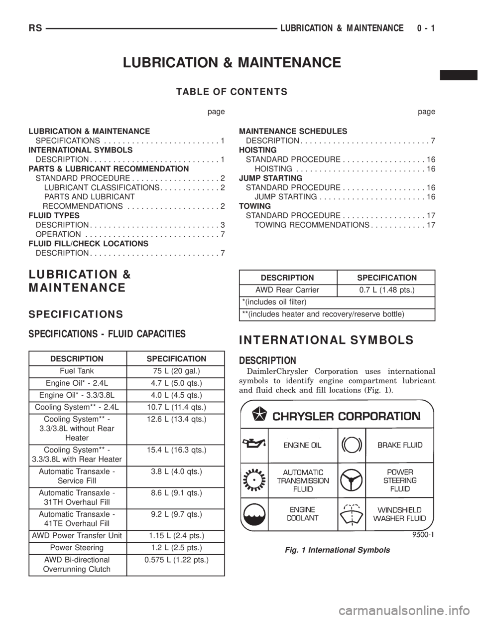
DESCRIPTION
DaimlerChrysler Corporation uses international
symbols to identify engine compartment lubricant
and fluid check and fill locations (Fig. 1).
Fig. 1 International Symbols
RSLUBRICATION & MAINTENANCE0-1