2001 CHRYSLER VOYAGER tow
[x] Cancel search: towPage 1505 of 4284
transmission in NEUTRAL and turn the ignition
OFF.
(3) On disabled vehicle, place gear selector in park
or neutral and set park brake. Turn off all accesso-
ries.
(4) Connect jumper cables to booster battery. RED
clamp to positive terminal (+). BLACK clamp to neg-
ative terminal (-). DO NOT allow clamps at opposite
end of cables to touch, electrical arc will result.
Review all warnings in this procedure.
(5) On disabled vehicle, connect RED jumper cable
clamp to positive (+) terminal. Connect BLACK
jumper cable clamp to engine ground as close to the
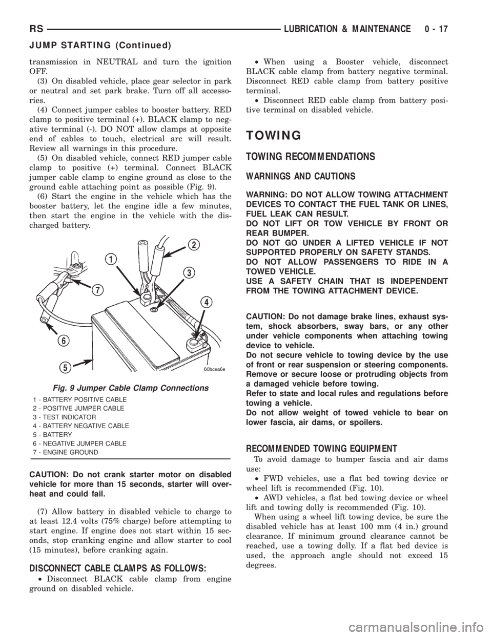
ground cable attaching point as possible (Fig. 9).
(6) Start the engine in the vehicle which has the
booster battery, let the engine idle a few minutes,
then start the engine in the vehicle with the dis-
charged battery.
CAUTION: Do not crank starter motor on disabled
vehicle for more than 15 seconds, starter will over-
heat and could fail.
(7) Allow battery in disabled vehicle to charge to
at least 12.4 volts (75% charge) before attempting to
start engine. If engine does not start within 15 sec-
onds, stop cranking engine and allow starter to cool
(15 minutes), before cranking again.
DISCONNECT CABLE CLAMPS AS FOLLOWS:
²Disconnect BLACK cable clamp from engine
ground on disabled vehicle.²When using a Booster vehicle, disconnect
BLACK cable clamp from battery negative terminal.
Disconnect RED cable clamp from battery positive
terminal.
²Disconnect RED cable clamp from battery posi-
tive terminal on disabled vehicle.
TOWING
TOWING RECOMMENDATIONS
WARNINGS AND CAUTIONS
WARNING: DO NOT ALLOW TOWING ATTACHMENT
DEVICES TO CONTACT THE FUEL TANK OR LINES,
FUEL LEAK CAN RESULT.
DO NOT LIFT OR TOW VEHICLE BY FRONT OR
REAR BUMPER.
DO NOT GO UNDER A LIFTED VEHICLE IF NOT
SUPPORTED PROPERLY ON SAFETY STANDS.
DO NOT ALLOW PASSENGERS TO RIDE IN A
TOWED VEHICLE.
USE A SAFETY CHAIN THAT IS INDEPENDENT
FROM THE TOWING ATTACHMENT DEVICE.
CAUTION: Do not damage brake lines, exhaust sys-
tem, shock absorbers, sway bars, or any other
under vehicle components when attaching towing
device to vehicle.
Do not secure vehicle to towing device by the use
of front or rear suspension or steering components.
Remove or secure loose or protruding objects from
a damaged vehicle before towing.
Refer to state and local rules and regulations before
towing a vehicle.
Do not allow weight of towed vehicle to bear on
lower fascia, air dams, or spoilers.
RECOMMENDED TOWING EQUIPMENT
To avoid damage to bumper fascia and air dams
use:
²FWD vehicles, use a flat bed towing device or
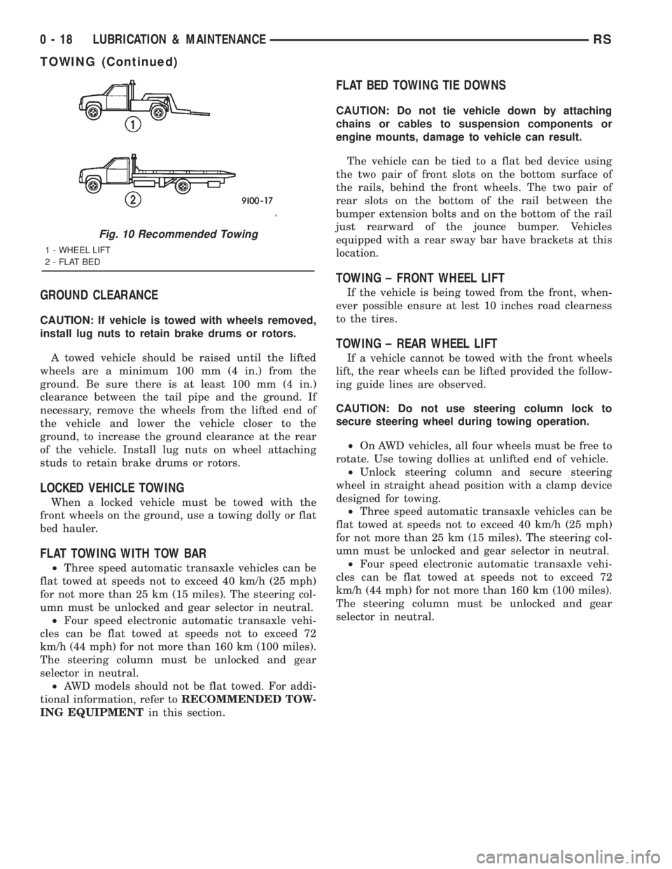
wheel lift is recommended (Fig. 10).
²AWD vehicles, a flat bed towing device or wheel
lift and towing dolly is recommended (Fig. 10).
When using a wheel lift towing device, be sure the
disabled vehicle has at least 100 mm (4 in.) ground
clearance. If minimum ground clearance cannot be
reached, use a towing dolly. If a flat bed device is
used, the approach angle should not exceed 15
degrees.
Fig. 9 Jumper Cable Clamp Connections
1 - BATTERY POSITIVE CABLE
2 - POSITIVE JUMPER CABLE
3 - TEST INDICATOR
4 - BATTERY NEGATIVE CABLE
5 - BATTERY
6 - NEGATIVE JUMPER CABLE
7 - ENGINE GROUND
RSLUBRICATION & MAINTENANCE0-17
JUMP STARTING (Continued)
Page 1506 of 4284
GROUND CLEARANCE
CAUTION: If vehicle is towed with wheels removed,
install lug nuts to retain brake drums or rotors.
A towed vehicle should be raised until the lifted
wheels are a minimum 100 mm (4 in.) from the
ground. Be sure there is at least 100 mm (4 in.)
clearance between the tail pipe and the ground. If
necessary, remove the wheels from the lifted end of
the vehicle and lower the vehicle closer to the
ground, to increase the ground clearance at the rear
of the vehicle. Install lug nuts on wheel attaching
studs to retain brake drums or rotors.
LOCKED VEHICLE TOWING
When a locked vehicle must be towed with the
front wheels on the ground, use a towing dolly or flat
bed hauler.
FLAT TOWING WITH TOW BAR
²Three speed automatic transaxle vehicles can be
flat towed at speeds not to exceed 40 km/h (25 mph)
for not more than 25 km (15 miles). The steering col-
umn must be unlocked and gear selector in neutral.
²Four speed electronic automatic transaxle vehi-
cles can be flat towed at speeds not to exceed 72
km/h (44 mph) for not more than 160 km (100 miles).
The steering column must be unlocked and gear
selector in neutral.
²AWD models should not be flat towed. For addi-
tional information, refer toRECOMMENDED TOW-
ING EQUIPMENTin this section.
FLAT BED TOWING TIE DOWNS
CAUTION: Do not tie vehicle down by attaching
chains or cables to suspension components or
engine mounts, damage to vehicle can result.
The vehicle can be tied to a flat bed device using
the two pair of front slots on the bottom surface of
the rails, behind the front wheels. The two pair of
rear slots on the bottom of the rail between the
bumper extension bolts and on the bottom of the rail
just rearward of the jounce bumper. Vehicles
equipped with a rear sway bar have brackets at this
location.
TOWING ± FRONT WHEEL LIFT
If the vehicle is being towed from the front, when-
ever possible ensure at lest 10 inches road clearness
to the tires.
TOWING ± REAR WHEEL LIFT
If a vehicle cannot be towed with the front wheels
lift, the rear wheels can be lifted provided the follow-
ing guide lines are observed.
CAUTION: Do not use steering column lock to
secure steering wheel during towing operation.
²On AWD vehicles, all four wheels must be free to
rotate. Use towing dollies at unlifted end of vehicle.
²Unlock steering column and secure steering
wheel in straight ahead position with a clamp device
designed for towing.
²Three speed automatic transaxle vehicles can be
flat towed at speeds not to exceed 40 km/h (25 mph)
for not more than 25 km (15 miles). The steering col-
umn must be unlocked and gear selector in neutral.
²Four speed electronic automatic transaxle vehi-
cles can be flat towed at speeds not to exceed 72
km/h (44 mph) for not more than 160 km (100 miles).
The steering column must be unlocked and gear
selector in neutral.
Fig. 10 Recommended Towing
1 - WHEEL LIFT
2 - FLAT BED
0 - 18 LUBRICATION & MAINTENANCERS
TOWING (Continued)
Page 1507 of 4284
LUBRICATION & MAINTENANCE - RG - 2.5 L TURBO
DIESEL
TABLE OF CONTENTS
page page
LUBRICATION & MAINTENANCE - RG - 2.5 L
TURBO DIESEL
SPECIFICATIONS.........................1
INTERNATIONAL SYMBOLS
DESCRIPTION............................2
FLUID TYPES
DESCRIPTION............................2
FLUID FILL/CHECK LOCATIONS
DESCRIPTION............................5
MAINTENANCE SCHEDULES
DESCRIPTION............................5HOISTING
STANDARD PROCEDURE...................7
HOISTING.............................7
JUMP STARTING
STANDARD PROCEDURE...................8
JUMP STARTING........................8
TOWING
STANDARD PROCEDURE...................8
TOWING RECOMMENDATIONS.............8
LUBRICATION &
MAINTENANCE - RG - 2.5 L
TURBO DIESEL
SPECIFICATIONS
SPECIFICATIONS - FLUID CAPACITIES
DESCRIPTION SPECIFICATION
Fuel Tank 75 L (20 gal.)
Fuel Tank (Diesel) 75 L (20 gal.)
Engine Oil* - 2.4 L 4.7 L (5.0 qts.)
Engine Oil* - 3.3 L 4.0 L (4.5 qts.)
Engine Oil* - 2.5 L 5.22 L (5.52 qts.)
Cooling System** - 2.4 L 10.7 L (11.4 qts.)
Cooling System** - 3.3 L
without Auxiliary Heater12.6 L (13.4 qts.)
Cooling System** - 3.3 L
with Auxiliary Heater15.4 L (16.3 qts.)
Cooling System** - 2.5 L
Turbo Diesel without
Auxiliary Heater13.8 L (14.6 qts.)
DESCRIPTION SPECIFICATION
Cooling System** - 2.5 L
Turbo Diesel with
Auxiliary Heater16.6 L (17.5 qts.)
Automatic Transaxle -
Service Fill3.8 L (4.0 qts.)
Automatic Transaxle -
31TH Overhaul Fill8.6 L (9.1 qts.)
Automatic Transaxle -
41TE Overhaul Fill9.2 L (9.7 qts.)
Manual Transaxle (T850
5-speed)2.4-2.7 L (2.5-2.9 qts.)
AWD Power Transfer Unit 1.15 L (2.4 pts.)
Power Steering 1.2 L (2.5 pts.)
AWD Bi-directional
Overrunning Clutch0.575 L (1.22 pts.)
AWD Rear Carrier 0.7 L (1.48 pts.)
*(includes oil filter)
**(includes heater and recovery/reserve bottle)
RGLUBRICATION & MAINTENANCE - RG - 2.5 L TURBO DIESEL0a-1
Page 1512 of 4284
160 000 km (100 000 miles)
²Change engine oil. (1)
²Replace engine oil filter.
²Replace air filter element.
²Replace fuel filter/water separator element. (2)
²Check alignment.
²Flush and replace engine coolant. (3)
180 000 km (110 000 miles)
²Change engine oil. (1)
²Replace engine oil filter.
²Inspect air filter element. Replace as necessary.
IMPORTANT: Inspection and service should also
be performed any time a malfunction is observed or
suspected. Retain all receipts.
²Change oil every 12 months regardless of mile-
age.
²The fuel filter/water separator element should
be replaced once a year if the vehicle is driven less
than 40 000 km annually or if power loss from fuel
starvation is detected.
²
Flush and replace engine coolant every 60 months
even if the vehicle is driven less than 160 000 km.
SCHEDULE ªBº
Follow this schedule if the vehicle is operated
under one or more of the following conditions.
²Day or night temperatures are below 0É C
(32É F).
²Stop and go driving.
²Extensive engine idling.
²Driving in dusty conditions.
²Short trips of less than 16.2 km (10 miles).
²More than 50% of driving is at sustained high
speeds during hot weather, above 32É C (90É F).
²Trailer towing.
²Taxi, police, or delivery service (commercial ser-
vice).
10 000 km (6 000 Miles)
²Change engine oil. (1)
²Replace engine oil filter.
²Inspect air filter element.
20 000 km (12 000 Miles)
²Change engine oil. (1)
²Replace engine oil filter.
²Replace air filter element.
²Replace fuel filter/water separator element. (2)
²Check alignment.
30 000 km (18 000 Miles)
²Change engine oil. (1)
²Replace engine oil filter.
²Inspect air filter element.
40 000 km (24 000 Miles)
²Change engine oil. (1)
²Replace engine oil filter.
²Replace air filter element.
²Replace fuel filter/water separator element. (2)
²Check alignment.
²Change manual transaxle fluid.
50 000 km (31 000 Miles)
²Change engine oil. (1)
²Replace engine oil filter.
²Inspect air filter element.
60 000 km (37 000 Miles)
²Change engine oil. (1)
²Replace engine oil filter.
²Replace air filter element.
²Replace fuel filter/water separator element. (2)
²Check alignment.
70 000 km (43 000 Miles)
²Change engine oil. (1)
²Replace engine oil filter.
²Inspect air filter element.
80 000 km (49 000 Miles)
²Change engine oil. (1)
²Replace engine oil filter.
²Replace air filter element.
²Replace fuel filter/water separator element. (2)
²Check alignment.
²Change manual transaxle fluid.
90 000 km (55 000 Miles)
²Change engine oil. (1)
²Replace engine oil filter.
²Inspect air filter element.
100 000 km (62 000 Miles)
²Change engine oil. (1)
²Replace engine oil filter.
²Replace air filter element.
²Replace fuel filter/water separator element. (2)
110 000 km (68 000 Miles)
²Change engine oil. (1)
²Replace engine oil filter.
²Inspect air filter element.
²Replace fuel filter/water separator element. (2)
²Check alignment.
120 000 km (74 000 Miles)
²Change engine oil. (1)
²Replace engine oil filter.
²Replace air filter element.
²Change manual transaxle fluid.
130 000 km (80 000 Miles)
²Change engine oil. (1)
²Replace engine oil filter.
0a - 6 LUBRICATION & MAINTENANCE - RG - 2.5 L TURBO DIESELRG
MAINTENANCE SCHEDULES (Continued)
Page 1514 of 4284
JUMP STARTING
STANDARD PROCEDURE - JUMP STARTING
(1) Raise hood on disabled vehicle and visually
inspect engine compartment for:
²Battery cable clamp condition, clean if necessary.
²Frozen battery.
²Yellow or bright color test indicator, if equipped.
²Low battery fluid level.
²Generator drive belt condition and tension.
²Fuel fumes or leakage, correct if necessary.
CAUTION: If the cause of starting problem on dis-
abled vehicle is severe, damage to booster vehicle
charging system can result.
(2) When using another vehicle as a booster
source, park the booster vehicle within cable reach.
Turn off all accessories, set the parking brake, place
the automatic transmission in PARK or the manual
transmission in NEUTRAL and turn the ignition
OFF.
(3)
On disabled vehicle, place gear selector in park
or neutral and set park brake. Turn off all accessories.
(4) Connect jumper cables to booster battery. RED
clamp to positive terminal (+). BLACK clamp to neg-
ative terminal (-). DO NOT allow clamps at opposite
end of cables to touch, electrical arc will result.
Review all warnings in this procedure.
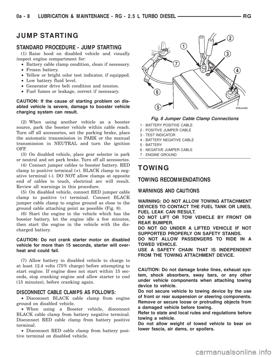
(5) On disabled vehicle, connect RED jumper cable
clamp to positive (+) terminal. Connect BLACK
jumper cable clamp to engine ground as close to the
ground cable attaching point as possible (Fig. 8).
(6) Start the engine in the vehicle which has the
booster battery, let the engine idle a few minutes,
then start the engine in the vehicle with the dis-
charged battery.
CAUTION: Do not crank starter motor on disabled
vehicle for more than 15 seconds, starter will over-
heat and could fail.
(7) Allow battery in disabled vehicle to charge to
at least 12.4 volts (75% charge) before attempting to
start engine. If engine does not start within 15 sec-
onds, stop cranking engine and allow starter to cool
(15 minutes), before cranking again.
DISCONNECT CABLE CLAMPS AS FOLLOWS:
²Disconnect BLACK cable clamp from engine
ground on disabled vehicle.
²When using a Booster vehicle, disconnect
BLACK cable clamp from battery negative terminal.
Disconnect RED cable clamp from battery positive
terminal.
²Disconnect RED cable clamp from battery posi-
tive terminal on disabled vehicle.
TOWING
TOWING RECOMMENDATIONS
WARNINGS AND CAUTIONS
WARNING: DO NOT ALLOW TOWING ATTACHMENT
DEVICES TO CONTACT THE FUEL TANK OR LINES,
FUEL LEAK CAN RESULT.
DO NOT LIFT OR TOW VEHICLE BY FRONT OR
REAR BUMPER.
DO NOT GO UNDER A LIFTED VEHICLE IF NOT
SUPPORTED PROPERLY ON SAFETY STANDS.
DO NOT ALLOW PASSENGERS TO RIDE IN A
TOWED VEHICLE.
USE A SAFETY CHAIN THAT IS INDEPENDENT
FROM THE TOWING ATTACHMENT DEVICE.
CAUTION: Do not damage brake lines, exhaust sys-
tem, shock absorbers, sway bars, or any other
under vehicle components when attaching towing
device to vehicle.
Do not secure vehicle to towing device by the use
of front or rear suspension or steering components.
Remove or secure loose or protruding objects from
a damaged vehicle before towing.
Refer to state and local rules and regulations before
towing a vehicle.
Do not allow weight of towed vehicle to bear on
lower fascia, air dams, or spoilers.
Fig. 8 Jumper Cable Clamp Connections
1 - BATTERY POSITIVE CABLE
2 - POSITIVE JUMPER CABLE
3 - TEST INDICATOR
4 - BATTERY NEGATIVE CABLE
5 - BATTERY
6 - NEGATIVE JUMPER CABLE
7 - ENGINE GROUND
0a - 8 LUBRICATION & MAINTENANCE - RG - 2.5 L TURBO DIESELRG
Page 1515 of 4284
RECOMMENDED TOWING EQUIPMENT
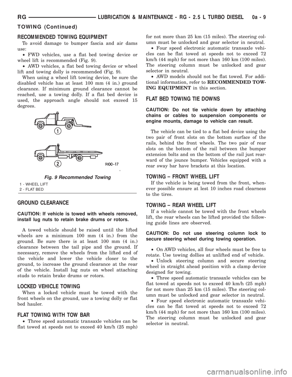
To avoid damage to bumper fascia and air dams
use:
²FWD vehicles, use a flat bed towing device or
wheel lift is recommended (Fig. 9).
²AWD vehicles, a flat bed towing device or wheel
lift and towing dolly is recommended (Fig. 9).
When using a wheel lift towing device, be sure the
disabled vehicle has at least 100 mm (4 in.) ground
clearance. If minimum ground clearance cannot be
reached, use a towing dolly. If a flat bed device is
used, the approach angle should not exceed 15
degrees.
GROUND CLEARANCE
CAUTION: If vehicle is towed with wheels removed,
install lug nuts to retain brake drums or rotors.
A towed vehicle should be raised until the lifted
wheels are a minimum 100 mm (4 in.) from the
ground. Be sure there is at least 100 mm (4 in.)
clearance between the tail pipe and the ground. If
necessary, remove the wheels from the lifted end of
the vehicle and lower the vehicle closer to the
ground, to increase the ground clearance at the rear
of the vehicle. Install lug nuts on wheel attaching
studs to retain brake drums or rotors.
LOCKED VEHICLE TOWING
When a locked vehicle must be towed with the
front wheels on the ground, use a towing dolly or flat
bed hauler.
FLAT TOWING WITH TOW BAR
²Three speed automatic transaxle vehicles can be
flat towed at speeds not to exceed 40 km/h (25 mph)for not more than 25 km (15 miles). The steering col-
umn must be unlocked and gear selector in neutral.
²Four speed electronic automatic transaxle vehi-
cles can be flat towed at speeds not to exceed 72
km/h (44 mph) for not more than 160 km (100 miles).
The steering column must be unlocked and gear
selector in neutral.
²AWD models should not be flat towed. For addi-
tional information, refer toRECOMMENDED TOW-
ING EQUIPMENTin this section.
FLAT BED TOWING TIE DOWNS
CAUTION: Do not tie vehicle down by attaching
chains or cables to suspension components or
engine mounts, damage to vehicle can result.
The vehicle can be tied to a flat bed device using the
two pair of front slots on the bottom surface of the
rails, behind the front wheels. The two pair of rear
slots on the bottom of the rail between the bumper
extension bolts and on the bottom of the rail just rear-
ward of the jounce bumper. Vehicles equipped with a
rear sway bar have brackets at this location.
TOWING ± FRONT WHEEL LIFT
If the vehicle is being towed from the front, when-
ever possible ensure at lest 10 inches road clearness
to the tires.
TOWING ± REAR WHEEL LIFT
If a vehicle cannot be towed with the front wheels
lift, the rear wheels can be lifted provided the follow-
ing guide lines are observed.
CAUTION: Do not use steering column lock to
secure steering wheel during towing operation.
²On AWD vehicles, all four wheels must be free to
rotate. Use towing dollies at unlifted end of vehicle.
²Unlock steering column and secure steering
wheel in straight ahead position with a clamp device
designed for towing.
²Three speed automatic transaxle vehicles can be
flat towed at speeds not to exceed 40 km/h (25 mph)
for not more than 25 km (15 miles). The steering col-
umn must be unlocked and gear selector in neutral.
²Four speed electronic automatic transaxle vehi-
cles can be flat towed at speeds not to exceed 72
km/h (44 mph) for not more than 160 km (100 miles).
The steering column must be unlocked and gear
selector in neutral.
Fig. 9 Recommended Towing
1 - WHEEL LIFT
2 - FLAT BED
RGLUBRICATION & MAINTENANCE - RG - 2.5 L TURBO DIESEL0a-9
TOWING (Continued)
Page 1518 of 4284
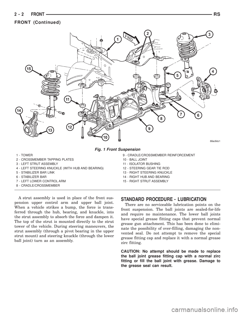
A strut assembly is used in place of the front sus-
pension upper control arm and upper ball joint.
When a vehicle strikes a bump, the force is trans-
ferred through the hub, bearing, and knuckle, into
the strut assembly to absorb the force and dampen it.
The top of the strut is mounted directly to the strut
tower of the vehicle. During steering maneuvers, the
strut assembly (through a pivot bearing in the upper
strut mount) and steering knuckle (through the lower
ball joint) turn as an assembly.STANDARD PROCEDURE - LUBRICATION
There are no serviceable lubrication points on the
front suspension. The ball joints are sealed-for-life
and require no maintenance. The lower ball joints
have special grease fitting caps that prevent normal
grease gun attachment. This has been done to elimi-
nate the possibility of over-filling, damaging the non-
vented seal. Do not attempt to remove the special
grease fitting cap and replace it with a normal grease
zirc fitting.
CAUTION: No attempt should be made to replace
the ball joint grease fitting cap with a normal zirc
fitting or fill the ball joint with grease. Damage to
the grease seal can result.
Fig. 1 Front Suspension
1 - TOWER
2 - CROSSMEMBER TAPPING PLATES
3 - LEFT STRUT ASSEMBLY
4 - LEFT STEERING KNUCKLE (WITH HUB AND BEARING)
5 - STABILIZER BAR LINK
6 - STABILIZER BAR
7 - LEFT LOWER CONTROL ARM
8 - CRADLE/CROSSMEMBER9 - CRADLE/CROSSMEMBER REINFORCEMENT
10 - BALL JOINT
11 - ISOLATOR BUSHING
12 - STEERING GEAR TIE ROD
13 - RIGHT STEERING KNUCKLE
14 - RIGHT HUB AND BEARING
15 - RIGHT STRUT ASSEMBLY
2 - 2 FRONTRS
FRONT (Continued)
Page 1519 of 4284
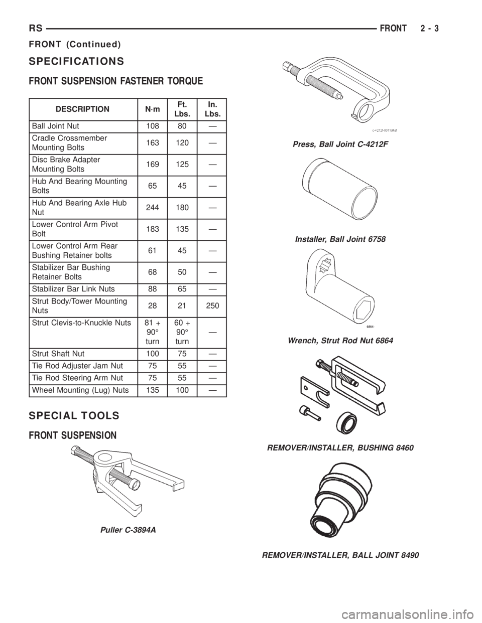
SPECIFICATIONS
FRONT SUSPENSION FASTENER TORQUE
DESCRIPTION N´mFt.
Lbs.In.
Lbs.
Ball Joint Nut 108 80 Ð
Cradle Crossmember
Mounting Bolts163 120 Ð
Disc Brake Adapter
Mounting Bolts169 125 Ð
Hub And Bearing Mounting
Bolts65 45 Ð
Hub And Bearing Axle Hub
Nut244 180 Ð
Lower Control Arm Pivot
Bolt183 135 Ð
Lower Control Arm Rear
Bushing Retainer bolts61 45 Ð
Stabilizer Bar Bushing
Retainer Bolts68 50 Ð
Stabilizer Bar Link Nuts 88 65 Ð
Strut Body/Tower Mounting
Nuts28 21 250
Strut Clevis-to-Knuckle Nuts 81 +
90É
turn60 +
90É
turnÐ
Strut Shaft Nut 100 75 Ð
Tie Rod Adjuster Jam Nut 75 55 Ð
Tie Rod Steering Arm Nut 75 55 Ð
Wheel Mounting (Lug) Nuts 135 100 Ð
SPECIAL TOOLS
FRONT SUSPENSION
Puller C-3894A
Press, Ball Joint C-4212F
Installer, Ball Joint 6758
Wrench, Strut Rod Nut 6864
REMOVER/INSTALLER, BUSHING 8460
REMOVER/INSTALLER, BALL JOINT 8490
RSFRONT2-3
FRONT (Continued)