2001 CHRYSLER VOYAGER fuel
[x] Cancel search: fuelPage 17 of 4284
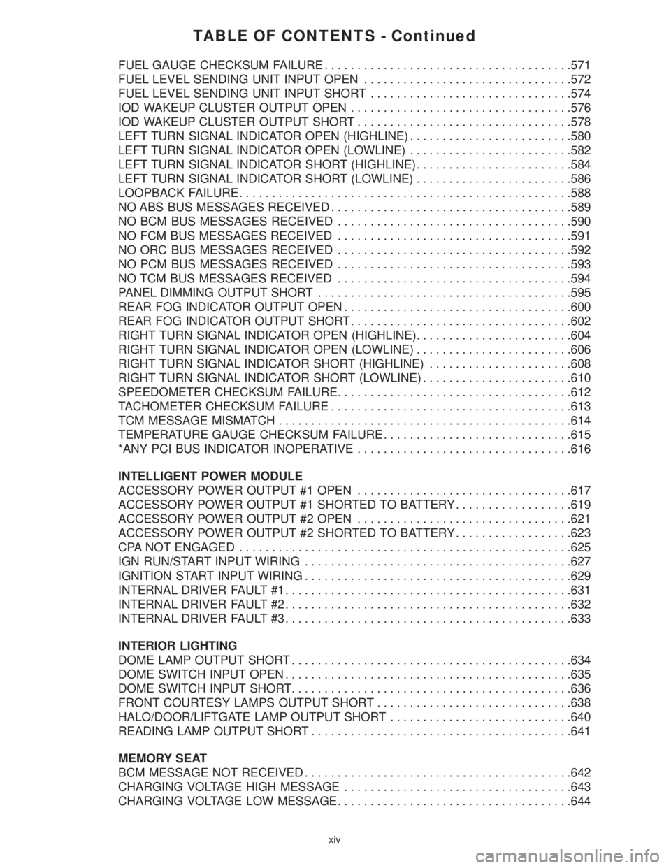
TABLE OF CONTENTS - Continued
FUEL GAUGE CHECKSUM FAILURE......................................571
FUEL LEVEL SENDING UNIT INPUT OPEN................................572
FUEL LEVEL SENDING UNIT INPUT SHORT...............................574
IOD WAKEUP CLUSTER OUTPUT OPEN..................................576
IOD WAKEUP CLUSTER OUTPUT SHORT.................................578
LEFT TURN SIGNAL INDICATOR OPEN (HIGHLINE).........................580
LEFT TURN SIGNAL INDICATOR OPEN (LOWLINE).........................582
LEFT TURN SIGNAL INDICATOR SHORT (HIGHLINE)........................584
LEFT TURN SIGNAL INDICATOR SHORT (LOWLINE)........................586
LOOPBACK FAILURE...................................................588
NO ABS BUS MESSAGES RECEIVED.....................................589
NO BCM BUS MESSAGES RECEIVED....................................590
NO FCM BUS MESSAGES RECEIVED....................................591
NO ORC BUS MESSAGES RECEIVED....................................592
NO PCM BUS MESSAGES RECEIVED....................................593
NO TCM BUS MESSAGES RECEIVED....................................594
PANEL DIMMING OUTPUT SHORT.......................................595
REAR FOG INDICATOR OUTPUT OPEN...................................600
REAR FOG INDICATOR OUTPUT SHORT..................................602
RIGHT TURN SIGNAL INDICATOR OPEN (HIGHLINE)........................604
RIGHT TURN SIGNAL INDICATOR OPEN (LOWLINE)........................606
RIGHT TURN SIGNAL INDICATOR SHORT (HIGHLINE)......................608
RIGHT TURN SIGNAL INDICATOR SHORT (LOWLINE).......................610
SPEEDOMETER CHECKSUM FAILURE....................................612
TACHOMETER CHECKSUM FAILURE.....................................613
TCM MESSAGE MISMATCH.............................................614
TEMPERATURE GAUGE CHECKSUM FAILURE.............................615
*ANY PCI BUS INDICATOR INOPERATIVE.................................616
INTELLIGENT POWER MODULE
ACCESSORY POWER OUTPUT #1 OPEN.................................617
ACCESSORY POWER OUTPUT #1 SHORTED TO BATTERY..................619
ACCESSORY POWER OUTPUT #2 OPEN.................................621
ACCESSORY POWER OUTPUT #2 SHORTED TO BATTERY..................623
CPA NOT ENGAGED...................................................625
IGN RUN/START INPUT WIRING.........................................627
IGNITION START INPUT WIRING.........................................629
INTERNAL DRIVER FAULT #1............................................631
INTERNAL DRIVER FAULT #2............................................632
INTERNAL DRIVER FAULT #3............................................633
INTERIOR LIGHTING
DOME LAMP OUTPUT SHORT...........................................634
DOME SWITCH INPUT OPEN............................................635
DOME SWITCH INPUT SHORT...........................................636
FRONT COURTESY LAMPS OUTPUT SHORT..............................638
HALO/DOOR/LIFTGATE LAMP OUTPUT SHORT............................640
READING LAMP OUTPUT SHORT........................................641
MEMORY SEAT
BCM MESSAGE NOT RECEIVED.........................................642
CHARGING VOLTAGE HIGH MESSAGE...................................643
CHARGING VOLTAGE LOW MESSAGE....................................644
xiv
Page 39 of 4284
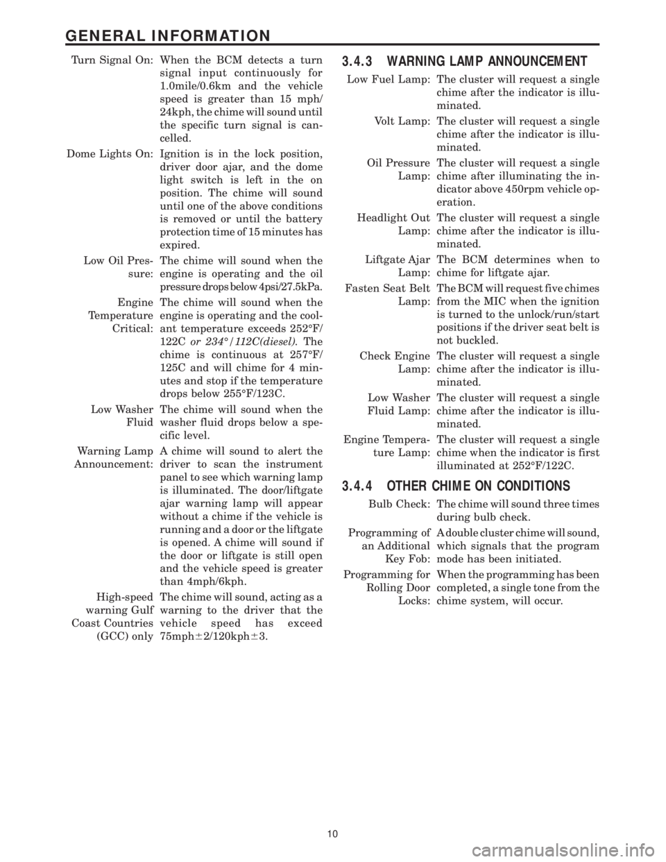
Turn Signal On: When the BCM detects a turn
signal input continuously for
1.0mile/0.6km and the vehicle
speed is greater than 15 mph/
24kph, the chime will sound until
the specific turn signal is can-
celled.
Dome Lights On: Ignition is in the lock position,
driver door ajar, and the dome
light switch is left in the on
position. The chime will sound
until one of the above conditions
is removed or until the battery
protection time of 15 minutes has
expired.
Low Oil Pres-
sure:The chime will sound when the
engine is operating and the oil
pressure drops below 4psi/27.5kPa.
Engine
Temperature
Critical:The chime will sound when the
engine is operating and the cool-
ant temperature exceeds 252ÉF/
122Cor 234É/112C(diesel).The
chime is continuous at 257ÉF/
125C and will chime for 4 min-
utes and stop if the temperature
drops below 255ÉF/123C.
Low Washer
FluidThe chime will sound when the
washer fluid drops below a spe-
cific level.
Warning Lamp
Announcement:A chime will sound to alert the
driver to scan the instrument
panel to see which warning lamp
is illuminated. The door/liftgate
ajar warning lamp will appear
without a chime if the vehicle is
running and a door or the liftgate
is opened. A chime will sound if
the door or liftgate is still open
and the vehicle speed is greater
than 4mph/6kph.
High-speed
warning Gulf
Coast Countries
(GCC) onlyThe chime will sound, acting as a
warning to the driver that the
vehicle speed has exceed
75mph62/120kph63.3.4.3 WARNING LAMP ANNOUNCEMENT
Low Fuel Lamp: The cluster will request a single
chime after the indicator is illu-
minated.
Volt Lamp: The cluster will request a single
chime after the indicator is illu-
minated.
Oil Pressure
Lamp:The cluster will request a single
chime after illuminating the in-
dicator above 450rpm vehicle op-
eration.
Headlight Out
Lamp:The cluster will request a single
chime after the indicator is illu-
minated.
Liftgate Ajar
Lamp:The BCM determines when to
chime for liftgate ajar.
Fasten Seat Belt
Lamp:The BCM will request five chimes
from the MIC when the ignition
is turned to the unlock/run/start
positions if the driver seat belt is
not buckled.
Check Engine
Lamp:The cluster will request a single
chime after the indicator is illu-
minated.
Low Washer
Fluid Lamp:The cluster will request a single
chime after the indicator is illu-
minated.
Engine Tempera-
ture Lamp:The cluster will request a single
chime when the indicator is first
illuminated at 252ÉF/122C.
3.4.4 OTHER CHIME ON CONDITIONS
Bulb Check: The chime will sound three times
during bulb check.
Programming of
an Additional
Key Fob:A double cluster chime will sound,
which signals that the program
mode has been initiated.
Programming for
Rolling Door
Locks:When the programming has been
completed, a single tone from the
chime system, will occur.
10
GENERAL INFORMATION
Page 48 of 4284
3.9.2.11 HVAC DIAGNOSTICS
The A/C ± Heater Control Module is fully addres-
sable with the DRBIIIt. Two of the Control Mod-
ule's diagnostic capabilities that the DRBIIItwill
actuate include the A/C Cooldown Test to test A/C
system performance and the HVAC Door Recalibra-
tion Test to determine actuator travel span. After
performing either test, the Control Module will
display one or more messages on the DRBIIIt
screen. The message will indicate either that the
HVAC system passed the test or that there is a fault
currently active in the HVAC system. The DRBIIIt
can also extract active and stored Diagnostic Trou-
ble Codes (DTCs) from the control module. Active
DTCs are faults that currently exit in the HVAC
system. Active DTCs cannot be erased until the
condition causing the code is repaired. Stored DTCs
are faults that occurred in the HVAC system since
the control module received the last ªclear diagnos-
tic infoº message.
3.10 CABIN HEATER
NOTE: The Cabin Heater, also known as the
Diesel Cabin Heater Assist (DCHA), will be
referred to as the DCHA throughout most of
the General Information and the Diagnostic
Procedures in this manual.
3.10.1 GENERAL SAFETY INFORMATION
WARNING: DO NOT OPERATE THE DCHA IN
AN ENCLOSED AREA SUCH AS A GARAGE
THAT DOES NOT HAVE EXHAUST
VENTILATION FACILITIES. ALWAYS VENT
THE DCHA's EXHAUST WHEN OPERATING
THE DCHA. FAILURE TO FOLLOW THESE
INSTRUCTIONS MAY RESULT IN PERSONAL
INJURY OR DEATH.
WARNING: ALLOW THE DCHA ASSEMBLY
TO COOL BEFORE PERFORMING A COM-
PONENT INSPECTION/REPAIR/REPLACE-
MENT. FAILURE TO FOLLOW THESE
INSTRUCTIONS MAY RESULT IN PERSONAL
INJURY.
WARNING: ALWAYS DISCONNECT THE
VEHICLE'S BATTERY PRIOR TO PER-
FORMING ANY TYPE OF WORK ON THE
DCHA. FAILURE TO FOLLOW THESE
INSTRUCTIONS MAY RESULT IN PERSONAL
INJURY OR DEATH.WARNING: NEVER ATTEMPT TO REPAIR THE
DCHA HEATER MODULE OR ANY OF ITS
INTERNAL COMPONENTS. ALWAYS PER-
FORM DCHA COMPONENT REPLACEMENT
IN ACCORDANCE WITH THE SERVICE
INFORMATION. FAILURE TO FOLLOW
THESE INSTRUCTIONS MAY RESULT IN
PERSONAL INJURY OR DEATH.
CAUTION: Do not actuate the DCHA Field
Mode Test with the engine off. Failure to
follow these instructions may result in
internal damage to the DCHA Heater Module.
CAUTION: Always Perform The Cabin Heater
Pre-Test Prior To Performing Any Other Cabin
Heater Test For The Test Result To Be Valid.
NOTE: Do not disconnect the vehicle's
battery or the DCHA's main power-supply
while the DCHA is in operation or in
run-down mode. Failure to follow these
instructions may result in excess emissions
from the DCHA Heater Module.
NOTE: Failure to prime the Dosing Pump
after draining the DCHA fuel line will prevent
DCHA heater activation during the first
attempt to start the heater. This will also set a
Diagnostic Trouble Code (DTC) in the DCHA
Control's memory. Do not perform the Dosing
Pump Priming Procedure if an attempt was
made to start the DCHA without priming the
Dosing Pump first. This will put excess fuel
in the DCHA Heater Module and cause smoke
to emit from the DCHA exhaust pipe when
heater activation occurs.
NOTE: Waxed fuel can obstruct the fuel line
and reduce flow. Check for the appropriate
winter grade fuel and replace as necessary.
3.10.2 COMPONENT DESCRIPTION AND
OPERATION
3.10.2.1 DCHA ASSEMBLY
The DCHA is a supplemental heater designed to
pre-heat the engine's coolant in order to supply the
vehicle's occupants with heat prior to the engine
reaching operating temperature. The DCHA assem-
bly mounts underneath the vehicle on the left side
floor pan near the front door opening. The DCHA
assembly connects to the vehicle's heater hoses and
has a fuel supply line that connects to the vehicle's
fuel tank.
19
GENERAL INFORMATION
Page 49 of 4284

The DCHA assembly consists of a:
²combustion air fan assembly
²burner housing
²burner insert
²control unit/heat exchanger
²combustion chamber
²dosing pump
3.10.2.2 COMBUSTION AIR FAN
The combustion air fan assembly includes the:
²combustion air fan
²combustion air fan inlet
²fuel supply inlet
The combustion air fan delivers the air required
for combustion from the combustion air inlet to the
burner insert.
3.10.2.3 BURNER HOUSING
The burner housing includes the:
²coolant inlet
²coolant outlet
²exhaust outlet
The burner housing accommodates the burner
insert and is combined with the control unit/heat
exchanger as an assembly.
3.10.2.4 BURNER INSERT
The burner insert includes the:
²combustion pipe fuel cross section
²glow plug/flame sensor
Inside the burner insert fuel is distributed across
the combustion pipe fuel cross section. Combustion
of the fuel/air mixture takes place within the com-
bustion pipe to heat the exchanger. The glow plug/
flame sensor located in the burner insert ignites the
fuel/air mixture during heater start up. After heater
start up, the glow plug/flame sensor operates in the
flame sensor function. The glow plug/flame sensor
designed as an electrical resistor is located in the
burner insert opposite the flame side.
3.10.2.5 CONTROL UNIT/HEAT
EXCHANGER
The control unit/heat exchanger includes the:
²control unit
²temperature sensor
²overheat protection
²heat exchanger
²connector terminal
The control unit controls and monitors combus-
tion operation. The control unit is ventilated bymeans of a ventilation hose routed from the com-
bustion air collector compartment of the burner.
The heat exchanger transfers the heat generated by
combustion to the coolant circuit. The control unit/
heat exchanger and the burner housing are an
assembly and must not be disassembled.
The temperature sensor senses the coolant tem-
perature in the heat exchanger as an electrical
resistance. This signal is sent to the control unit for
processing.
The overheat protection, controlled by the tem-
perature resistor, protects the heater against undue
operating temperatures. The overheat protection
will switch the heater off if the water temperature
exceeds 105ÉC (221ÉF).
3.10.2.6 DOSING PUMP
The dosing pump is a combined delivery, dosing,
and shut-off system for the fuel supply of the heater.
The dosing pump receives its supply of fuel from the
vehicle's fuel tank.
3.10.3 OPERATION
3.10.3.1 ACTIVATION
When the ignition is in Run, the FCM monitors
the PCI bus for the Cabin Heater Activation re-
quest. The A/C ± Heater Control Module initiates
this request only when all conditions for Cabin
Heater activation are favorable (see below). The
request carries the status bit that the FCM requires
to activate its Cabin Heater Assist Control Output.
This output is a low side driver (coming from FCM
pin 15) which supplies a ground signal to the Cabin
Heater (pin 5). When the Cabin Heater receives this
ground signal input, it interprets this as an activa-
tion signal. The FCM low side driver is also capable
of diagnostic sensing. The driver will sense an open
circuit when the driver is off, and will sense a short
to voltage when the driver is on. The FCM will set
DTCs for both of these types of faults.
The DCHA will activate only when the:
²engine is running.
²coolant temperature is below 66ÉC (151ÉF).
²fuel tank has greater than 1/8 of a tank of fuel.
²Power switch on the A/C ± Heater Control Module
is on.
²Blend Control on the A/C ± Heater Control Mod-
ule is set above 95% reheat.
²Front Control Module (FCM) sees the Cabin
Heater Activation request that is bussed from the
A/C ± Heater Control Module.
When the DCHA starting sequence begins, the
glow plug and the combustion air fan are activated.
After 30 seconds, the fuel dosing pump begins oper-
20
GENERAL INFORMATION
Page 50 of 4284

ating and the combustion air fan operation is sus-
pended for 3 seconds. Subsequently, the combustion
air fan speed is increased in two ramps within 56
seconds to nearly full load operation. After a stabi-
lization phase of 15 seconds, the combustion air fan
speed is again increased in a ramp within 50
seconds to nearly full load. After reaching full load
fuel delivery, the glow plug is deactivated and the
combustion air fan operation is increased to full
load. During the subsequent 45 seconds, as well as
in normal operation, the glow plug functions as a
flame sensor to monitor the flame condition. After
all these events, the automatically controlled heat-
ing operation starts.
In case of a no flame or a flame out condition, a
restart is automatically initiated. If the no flame
condition persists, fuel delivery is stopped and the
heater enters an error lockout mode with a run-
down of the combustion air fan. This will set one or
more DTCs in the DCHA Control's memory. If six
continuous attempts to start the heater fail due to
one or more faults in the DCHA system, the heater
enters a heater lockout mode. This will set DTC
B1813 along with any other fault(s) that the DCHA
Control identified.
3.10.3.2 HEATING
During the automatically controlled heating op-
eration, when the coolant temperature reaches
72ÉC (162ÉF), the heater will switch to a part load
operation. When the coolant temperature reaches
75ÉC (167ÉF) or if the heater runs for longer than 76
minutes the heater will switch to a control idle
period. If the coolant temperature drops to 71ÉC
(160ÉF) during a control idle period, the heater will
perform a regular starting sequence into full load
operation. A drop in coolant temperature to 65ÉC
(149ÉF) during part load operation will cause the
heater to switch to a full load operation.
3.10.3.3 DEACTIVATION
The DCHA will deactivate if the:
²engine is turned off.
²coolant temperature reaches 75ÉC (167ÉF).
²heater runs longer than 76 minutes.
²fuel tank has less than 1/8 of a tank of fuel.
²Power switch on the A/C ± Heater Control Module
is off.
²Blend Control on the A/C ± Heater Control Mod-
ule is set below 75% reheat.
When the heater is deactivated, the combustion
stops and a run-down sequence begins. During the
run-down sequence, the combustion air fan contin-
ues operation to cool down the heater. The fan is
automatically switched off after the run-down se-
quence is complete. The run-down time and thecombustion air fan speed depend on the heater
operating condition at the time of deactivation.
Run-down time is approximately 175 seconds when
deactivated in full load operation and approxi-
mately 100 seconds when deactivated in part load
operation.
3.10.4 DIAGNOSTICS
The DCHA is fully addressable with the DRBIIIt.
System tests include a Field Mode Test to activate
the DCHA for diagnostic testing purposes. The
DCHA Control will store up to three DTCs in its
memory. If the Controller detects a new fault in the
DCHA system, one that is not already stored in its
memory, it will clear the oldest of the three stored
DTCs, and it will store the new fault's DTC. If the
Controller detects a reoccurrence of a stored fault, it
will overwrite that fault's DTC with the most recent
occurrence.
3.11 INSTRUMENT CLUSTER
The Instrument Cluster receives and sends mes-
sages to other modules via the PCI bus circuit. The
indicator lamps will illuminate briefly for a bulb
check when the ignition is turned from off to run.
All of the gauges receive their information via the
PCI bus from the powertrain control module and
body control module.
The gauges and the LEDs are not individually
replaceable thereby requiring complete replace-
ment of the Instrument Cluster if a repair is neces-
sary. In the event that the Instrument Cluster loses
communication with other modules on the PCI bus,
the cluster will display ªno busº in the VF display.
The Trip/Reset button is used to switch the dis-
play from trip to total mileage. Holding the button
when the display is in the trip mode will reset the
trip mileage. This button is also used to put the
cluster in self-diagnostic mode. The odometer dis-
play uses blue-green vacuum fluorescent digital
characters.
On base vehicles, the Instrument Cluster has
three gauges: Speedometer, Fuel and Engine Cool-
ant Temperature. A red dot moves transversely
through openings in the Instrument Cluster face
(P-R-N-D-2-1) to indicate the gear selected.
With all other models, the Instrument Cluster
also includes a Tachometer and uses a vacuum-
fluorescent shift indicator.
The odometer display and door/liftgate ajar indi-
cators turn on when a door is opened to assist both
the customer and service technician to view the
odometer without turning the ignition on.
21
GENERAL INFORMATION
Page 52 of 4284
contains a potentiometer to monitor the seat posi-
tion. To monitor the position of the motor, the
MSMM sends out a 5-volt reference on the sensor
supply circuit. The sensor is grounded back to the
module on a common ground circuit. Based on the
position of the sensor, the MSMM monitors the
voltage change through the sensor on a separate
signal circuit.
The MSMM stores the input value of each of the
four seat potentiometers in memory when the sys-
tem requests a set. The driver can initiate a mem-
ory recall, using either the door mounted memory
switch or the RKE transmitter (if the remote linked
to memory feature is enabled via the EVIC). When
initiated, the MSMM adjusts the four seat sensors
(by using the motors) to match the memorized seat
position data.
For safety, the memory seat recall is disabled by
the MSMM when the vehicle is out of park position
or if the speed is not zero. Any obstruction to seat
movement over a 2-second delay will cause the seat
to stop moving in which case a stalled motor would
be detected by the MSMM and the corresponding
seat output would be deactivated. However, if the
object obstructing the seat is removed, the seat will
function normally again.
3.13.2 MEMORY MIRRORS
Each outside mirror contains vertical and hori-
zontal bi-directional drive positioning motors and
position sensors. The MSMM provides a 5-volt
reference on the signal circuit to each position
sensor. The sensors share a common ground circuit.
The MSMM monitors the position of the mirror
motors by measuring the voltage on each signal
circuit. When a memory position is set, the MSMM
monitors and stores the position of the outside
mirrors. The MSMM adjusts the mirrors to the
appropriate positions when a memory recall mes-
sage is received from the RKE or is requested from
the memory set switch.
The power mirror switch during non-memory
operation operates both mirrors independently of
the MSMM.
3.14 OVERHEAD CONSOLE
3.14.1 COMPASS/MINI-TRIP COMPUTER
(CMTC)
The compass/mini-trip computer is located in the
overhead console. It displays to the driver the
direction the vehicle is traveling and the current
outside temperature, as well as the following trav-
eler navigational information: average fuel econ-
omy (AVG ECO), distance to empty (DTE), instan-
taneous fuel economy (ECO), elapsed time (ET),and trip odometer (ODO). The information needed
for the CMTC functions is received over the PCI bus
from other modules.
3.14.2 ELECTRONIC VEHICLE
INFORMATION CENTER (EVIC)
The Electronic Vehicle Information Center
(EVIC) includes all the same functions and is lo-
cated in the same area as the Compass/Mini-Trip
Computer, but it adds a number of warning mes-
sages. Also, the EVIC messages are spelled out on
the screen, for example, DISTANCE TO EMPTY,
where the Mini-Trip Computer displays only shows
DTE.
If the compass/mini-trip computer or EVIC has
been replaced, it may be necessary to reset the
calibration.
3.14.3 SETTING THE COMPASS
The compass/mini-trip computer and EVIC are
self-calibrated and requires no adjustment. The
word CAL will be displayed to indicate that the
compass is in the fast calibrating mode. CAL will
turn off after the vehicle has gone in three complete
circles without stopping, in an area free of magnetic
disturbance.
If the module displays the temperature while the
compass is blank or shows a false reading, the
vehicle must be demagnetized. See the service man-
ual for the proper procedure.
If the compass still goes blank after the vehicle is
demagnetized, the compass/mini-trip/EVIC module
must be replaced.
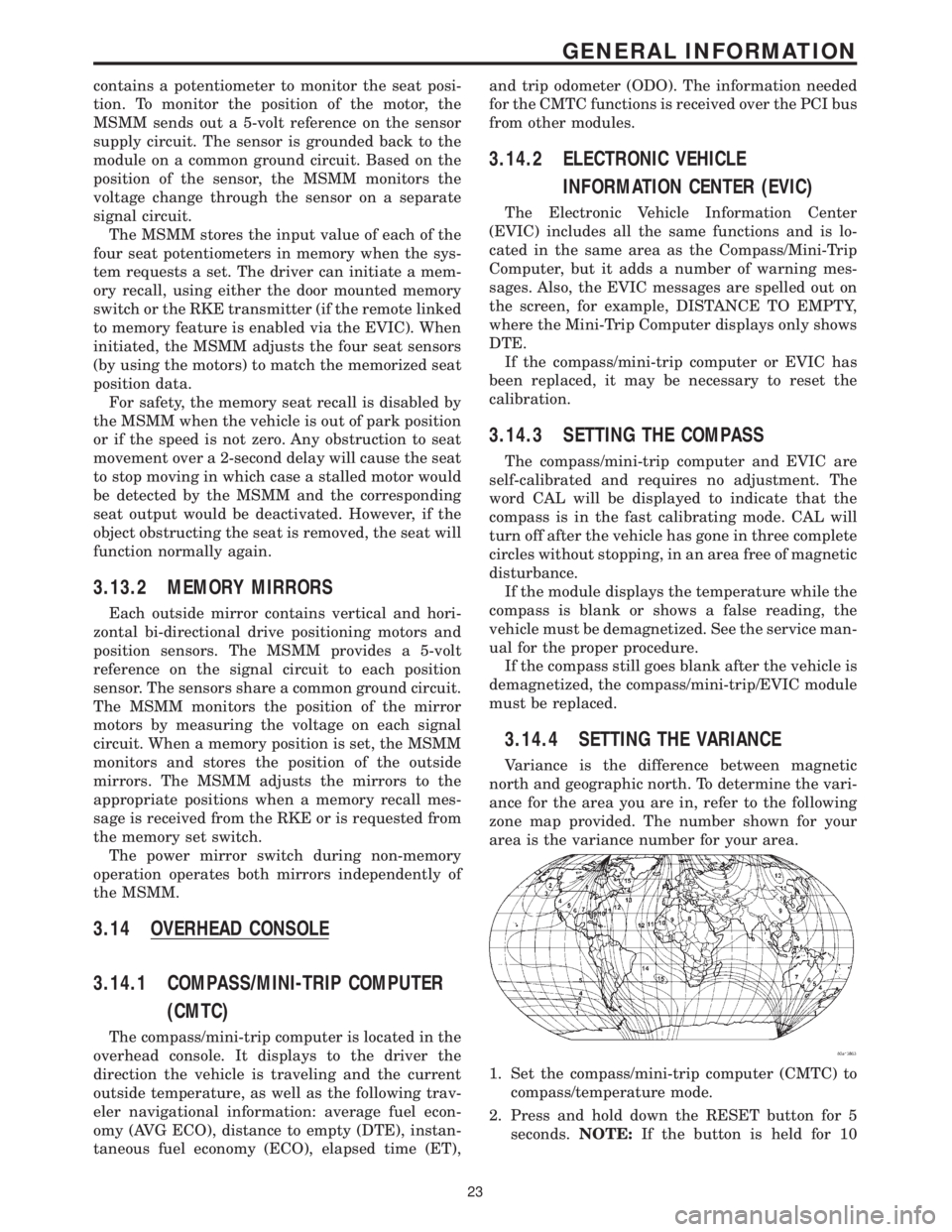
3.14.4 SETTING THE VARIANCE
Variance is the difference between magnetic
north and geographic north. To determine the vari-
ance for the area you are in, refer to the following
zone map provided. The number shown for your
area is the variance number for your area.
1. Set the compass/mini-trip computer (CMTC) to
compass/temperature mode.
2. Press and hold down the RESET button for 5
seconds.NOTE:If the button is held for 10
23
GENERAL INFORMATION
Page 327 of 4284
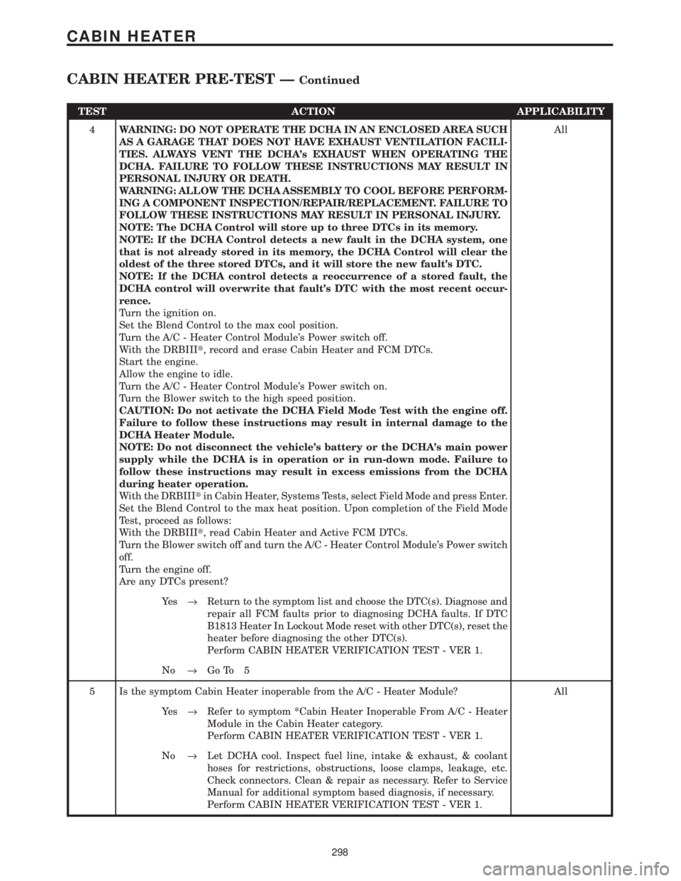
TEST ACTION APPLICABILITY
4WARNING: DO NOT OPERATE THE DCHA IN AN ENCLOSED AREA SUCH
AS A GARAGE THAT DOES NOT HAVE EXHAUST VENTILATION FACILI-
TIES. ALWAYS VENT THE DCHA's EXHAUST WHEN OPERATING THE
DCHA. FAILURE TO FOLLOW THESE INSTRUCTIONS MAY RESULT IN
PERSONAL INJURY OR DEATH.
WARNING: ALLOW THE DCHA ASSEMBLY TO COOL BEFORE PERFORM-
ING A COMPONENT INSPECTION/REPAIR/REPLACEMENT. FAILURE TO
FOLLOW THESE INSTRUCTIONS MAY RESULT IN PERSONAL INJURY.
NOTE: The DCHA Control will store up to three DTCs in its memory.
NOTE: If the DCHA Control detects a new fault in the DCHA system, one
that is not already stored in its memory, the DCHA Control will clear the
oldest of the three stored DTCs, and it will store the new fault's DTC.
NOTE: If the DCHA control detects a reoccurrence of a stored fault, the
DCHA control will overwrite that fault's DTC with the most recent occur-
rence.
Turn the ignition on.
Set the Blend Control to the max cool position.
Turn the A/C - Heater Control Module's Power switch off.
With the DRBIIIt, record and erase Cabin Heater and FCM DTCs.
Start the engine.
Allow the engine to idle.
Turn the A/C - Heater Control Module's Power switch on.
Turn the Blower switch to the high speed position.
CAUTION: Do not activate the DCHA Field Mode Test with the engine off.
Failure to follow these instructions may result in internal damage to the
DCHA Heater Module.
NOTE: Do not disconnect the vehicle's battery or the DCHA's main power
supply while the DCHA is in operation or in run-down mode. Failure to
follow these instructions may result in excess emissions from the DCHA
during heater operation.
With the DRBIIItin Cabin Heater, Systems Tests, select Field Mode and press Enter.
Set the Blend Control to the max heat position. Upon completion of the Field Mode
Test, proceed as follows:
With the DRBIIIt, read Cabin Heater and Active FCM DTCs.
Turn the Blower switch off and turn the A/C - Heater Control Module's Power switch
off.
Turn the engine off.
Are any DTCs present?All
Ye s®Return to the symptom list and choose the DTC(s). Diagnose and
repair all FCM faults prior to diagnosing DCHA faults. If DTC
B1813 Heater In Lockout Mode reset with other DTC(s), reset the
heater before diagnosing the other DTC(s).
Perform CABIN HEATER VERIFICATION TEST - VER 1.
No®Go To 5
5 Is the symptom Cabin Heater inoperable from the A/C - Heater Module? All
Ye s®Refer to symptom *Cabin Heater Inoperable From A/C - Heater
Module in the Cabin Heater category.
Perform CABIN HEATER VERIFICATION TEST - VER 1.
No®Let DCHA cool. Inspect fuel line, intake & exhaust, & coolant
hoses for restrictions, obstructions, loose clamps, leakage, etc.
Check connectors. Clean & repair as necessary. Refer to Service
Manual for additional symptom based diagnosis, if necessary.
Perform CABIN HEATER VERIFICATION TEST - VER 1.
298
CABIN HEATER
CABIN HEATER PRE-TEST ÐContinued
Page 329 of 4284

Symptom List:
B1800 NO START
B1801 FLAME OUT: DURING HEATING CYCLE
B1801 FLAME OUT: UNSTABLE OPERATION
Test Note: All symptoms listed above are diagnosed using the same tests.
The title for the tests will be B1800 NO START.
When Monitored and Set Condition:
B1800 NO START
When Monitored: After DCHA activation.
Set Condition: This DTC will set if the Flame Sensor resistance is not within the expected
parameters 160 sections after activation.
B1801 FLAME OUT: DURING HEATING CYCLE
When Monitored: After DCHA activation, and during subsequent start attempts.
Set Condition: This DTC will set if the Flame Sensor resistance is not within the expected
parameters.
B1801 FLAME OUT: UNSTABLE OPERATION
When Monitored: After DCHA activation.
Set Condition: This DTC will set if the Flame Sensor resistance is not within the expected
parameters.
POSSIBLE CAUSES
LOW FUEL LEVEL IN VEHICLE'S FUEL TANK
DOSING PUMP INOPERABLE, NO DOSING PUMP DTCS SET
DCHA FUEL LINE RESTRICTED/LEAKING/DAMAGED
DOSING PUMP
DCHA AIR INTAKE/EXHAUST RESTRICTED
DCHA HEATER MODULE FAULT
300
CABIN HEATER