2001 CHRYSLER VOYAGER compression ratio
[x] Cancel search: compression ratioPage 2789 of 4284
(7) Attach front engine mount bracket to lower
radiator support. Torque to 54N´m (40 ft. lbs.)
(8) Connect cabin heater coolant hose.
(9) Connect exhaust pipe to the turbocharger
downpipe flange. Torque to 28 N´m (250 in. lbs.)
(10) Connect reverse lamp electrical connector at
transmission.
(11) Connect both shifter cables (Refer to 21 -
TRANSMISSION/TRANSAXLE/MANUAL/GEAR
SHIFT CABLE - INSTALLATION).
(12) Connect the clutch slave cylinder quick dis-
connect connector (RHD only)(Refer to 6 - CLUTCH/
SLAVE CYLINDER - INSTALLATION).
(13) Install engine harness into bracket on trans-
mission.
(14) Lower vehicle.
(15) Connect fuel supply and return lines.
(16) Connect A/C lines to A/C compressor. Torque
to 23N´m (17 ft. lbs.)
(17) Route engine wiring harnes to proper location.
(18) Connect engine harness ground cables to
engine block
(19) Connect starter solenoid electrical connector
and battery feed wire to starter. Torque to 10N´m (90
in. lbs.)
(20) Connect A/C compressor, injection pump, glow
plugs, and coolant temperature sensor electrical con-
nectors.
(21) Connect generator electrical connector. Torque
to 9N´m (75 in. lbs.)
(22) Connect the fuel injector, fuel pressure sensor,
boost pressure/intake air temp sensor, cam sensor,
and egr solenoid electrical connectors (Fig. 9).
(23) Connect egr solenoid vacuum supply line to
brake boost vacuum supply line.
(24) Connect brake booster vacuum supply line.
(25) Connect heater core return hose to coolant
pipe.
(26) Connect lower radiator hose to engine (Fig. 8).
(27) Install charger air cooler inlet hose (Fig. 7).
(28) Install charge air cooler outlet hose (Fig. 7).
(29) Connect upper radiator hose to engine (Fig.
8).
(30) Install battery shield.
(31) Install coolant reserve pressure container
(Refer to 7 - COOLING/ENGINE/COOLANT RECOV-
ERY PRESS CONTAINER - INSTALLATION).
(32) Install power steering reservoir and bracket
(Fig. 5).
(33) Raise vehicle
(34) Connect oil pressure sensor, oil temperature
sensor, engine speed sensor, and vehicle speed sensor
electrical connector (Fig. 10).(35) Install suspension cradle in vehicle (Refer to
13 - FRAME & BUMPERS/FRAME/ENGINE CRA-
DLE CROSSMEMBER - INSTALLATION).
(36) Install both axle shaft assemblies (Refer to 3 -
DIFFERENTIAL & DRIVELINE/HALF SHAFT -
INSTALLATION).
(37) Connect the power steering supply, pressure,
and return lines to power steering pump (Fig. 5).
(38) Install the power steering line brackets on oil
pan (Fig. 5).
(39) Install lower splash shield and side panels.
(40) Install both front wheel and tire assemblies.
(41) Lower vehicle.
(42) Install air cleaner housing, MAF sensor, and
air intake tube assembly (Fig. 4).
(43) Refill transmission to proper level (Refer to 21
- TRANSMISSION/TRANSAXLE/MANUAL/FLUID -
STANDARD PROCEDURE).
(44) Refill engine coolant (Refer to 7 - COOLING/
ENGINE/COOLANT - STANDARD PROCEDURE).
(45) Recharge A/C system (Refer to 24 - HEATING
& AIR CONDITIONING/PLUMBING/REFRIGER-
ANT - STANDARD PROCEDURE) .
(46) Install engine cover (Refer to 9 - ENGINE -
INSTALLATION) (Fig. 3).
(47) Connect negative battery cable.
INSTALLATION - ENGINE COVER
(1) Install engine cover on engine.
(2) Install the engine cover mounting bolts (Fig.
11).
SPECIFICATIONS
SPECIFICATIONS - 2.5L COMMON RAIL
DIESEL ENGINE
ENGINE SPECIFICATIONS
DESCRIPTION SPECIFICATION
Type R2516C
Number of Cylinders 4
Bore 92 mm
Stroke 94 mm
Displacement 2499.5cc
Injection Order 1-3-4-2
Compression Ratio 17.5:1 ( 0.5)
Maximum Power 103kW (140 HP) @ 4000
RPM
Peak Torque 340Nm (34.6 kgm) @
1800 RPM
RGENGINE 2.5L TURBO DIESEL9a-7
ENGINE 2.5L TURBO DIESEL (Continued)
Page 2820 of 4284
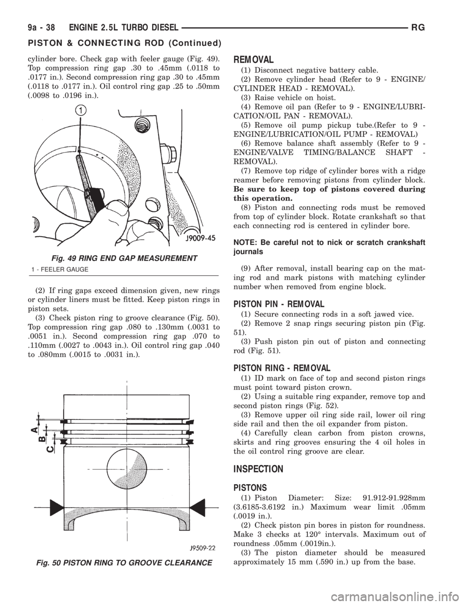
cylinder bore. Check gap with feeler gauge (Fig. 49).
Top compression ring gap .30 to .45mm (.0118 to
.0177 in.). Second compression ring gap .30 to .45mm
(.0118 to .0177 in.). Oil control ring gap .25 to .50mm
(.0098 to .0196 in.).
(2) If ring gaps exceed dimension given, new rings
or cylinder liners must be fitted. Keep piston rings in
piston sets.
(3) Check piston ring to groove clearance (Fig. 50).
Top compression ring gap .080 to .130mm (.0031 to
.0051 in.). Second compression ring gap .070 to
.110mm (.0027 to .0043 in.). Oil control ring gap .040
to .080mm (.0015 to .0031 in.).REMOVAL
(1) Disconnect negative battery cable.
(2) Remove cylinder head (Refer to 9 - ENGINE/
CYLINDER HEAD - REMOVAL).
(3) Raise vehicle on hoist.
(4) Remove oil pan (Refer to 9 - ENGINE/LUBRI-
CATION/OIL PAN - REMOVAL).
(5) Remove oil pump pickup tube.(Refer to 9 -
ENGINE/LUBRICATION/OIL PUMP - REMOVAL)
(6) Remove balance shaft assembly (Refer to 9 -
ENGINE/VALVE TIMING/BALANCE SHAFT -
REMOVAL).
(7) Remove top ridge of cylinder bores with a ridge
reamer before removing pistons from cylinder block.
Be sure to keep top of pistons covered during
this operation.
(8) Piston and connecting rods must be removed
from top of cylinder block. Rotate crankshaft so that
each connecting rod is centered in cylinder bore.
NOTE: Be careful not to nick or scratch crankshaft
journals
(9) After removal, install bearing cap on the mat-
ing rod and mark pistons with matching cylinder
number when removed from engine block.
PISTON PIN - REMOVAL
(1) Secure connecting rods in a soft jawed vice.
(2) Remove 2 snap rings securing piston pin (Fig.
51).
(3) Push piston pin out of piston and connecting
rod (Fig. 51).
PISTON RING - REMOVAL
(1) ID mark on face of top and second piston rings
must point toward piston crown.
(2) Using a suitable ring expander, remove top and
second piston rings (Fig. 52).
(3) Remove upper oil ring side rail, lower oil ring
side rail and then the oil expander from piston.
(4) Carefully clean carbon from piston crowns,
skirts and ring grooves ensuring the 4 oil holes in
the oil control ring groove are clear.
INSPECTION
PISTONS
(1) Piston Diameter: Size: 91.912-91.928mm
(3.6185-3.6192 in.) Maximum wear limit .05mm
(.0019 in.).
(2) Check piston pin bores in piston for roundness.
Make 3 checks at 120É intervals. Maximum out of
roundness .05mm (.0019in.).
(3) The piston diameter should be measured
approximately 15 mm (.590 in.) up from the base.
Fig. 49 RING END GAP MEASUREMENT
1 - FEELER GAUGE
Fig. 50 PISTON RING TO GROOVE CLEARANCE
9a - 38 ENGINE 2.5L TURBO DIESELRG
PISTON & CONNECTING ROD (Continued)
Page 2823 of 4284
(2) Before installing the ring compressor, make
sure the oil ring expander ends are butted together.
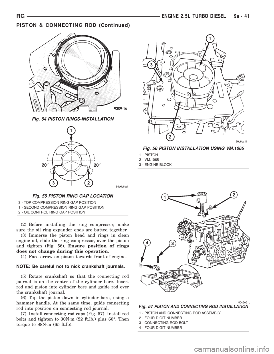
(3) Immerse the piston head and rings in clean
engine oil, slide the ring compressor, over the piston
and tighten (Fig. 56).Ensure position of rings
does not change during this operation.
(4) Face arrow on piston towards front of engine.
NOTE: Be careful not to nick crankshaft journals.
(5) Rotate crankshaft so that the connecting rod
journal is on the center of the cylinder bore. Insert
rod and piston into cylinder bore and guide rod over
the crankshaft journal.
(6) Tap the piston down in cylinder bore, using a
hammer handle. At the same time, guide connecting
rod into position on connecting rod journal.
(7) Install connecting rod caps (Fig. 57). Install rod
bolts and tighten to 30N´m (22 ft.lb.) plus 60É. Then
torque to 88N´m (65 ft.lb).
Fig. 54 PISTON RINGS-INSTALLATION
Fig. 55 PISTON RING GAP LOCATION
3 - TOP COMPRESSION RING GAP POSITION
1 - SECOND COMPRESSION RING GAP POSITION
2 - OIL CONTROL RING GAP POSITION
Fig. 56 PISTON INSTALLATION USING VM.1065
1 - PISTON
2 - VM.1065
3 - ENGINE BLOCK
Fig. 57PISTON AND CONNECTING ROD INSTALLATION
1 - PISTON AND CONNECTING ROD ASSEMBLY
2 - FOUR DIGIT NUMBER
3 - CONNECTING ROD BOLT
4 - FOUR DIGIT NUMBER
RGENGINE 2.5L TURBO DIESEL9a-41
PISTON & CONNECTING ROD (Continued)
Page 2856 of 4284
TURBOCHARGER SYSTEM
DESCRIPTION
CAUTION: The turbocharger is a performance part
and must not be tampered with. The wastegate
bracket is an integral part of the turbocharger. Tam-
pering with the wastegate components can reduce
durability by increasing cylinder pressure and ther-
mal loading due to incorrect inlet and exhaust man-
ifold pressure. Poor fuel economy and failure to
meet regulatory emissions laws may result. Increas-
ing the turbocharger boost WILL NOT increase
engine power.
The turbocharger is an exhaust-driven super-
charger which increases the pressure and density of
the air entering the engine. With the increase of air
entering the engine, more fuel can be injected into
the cylinders, which creates more power during com-
bustion.
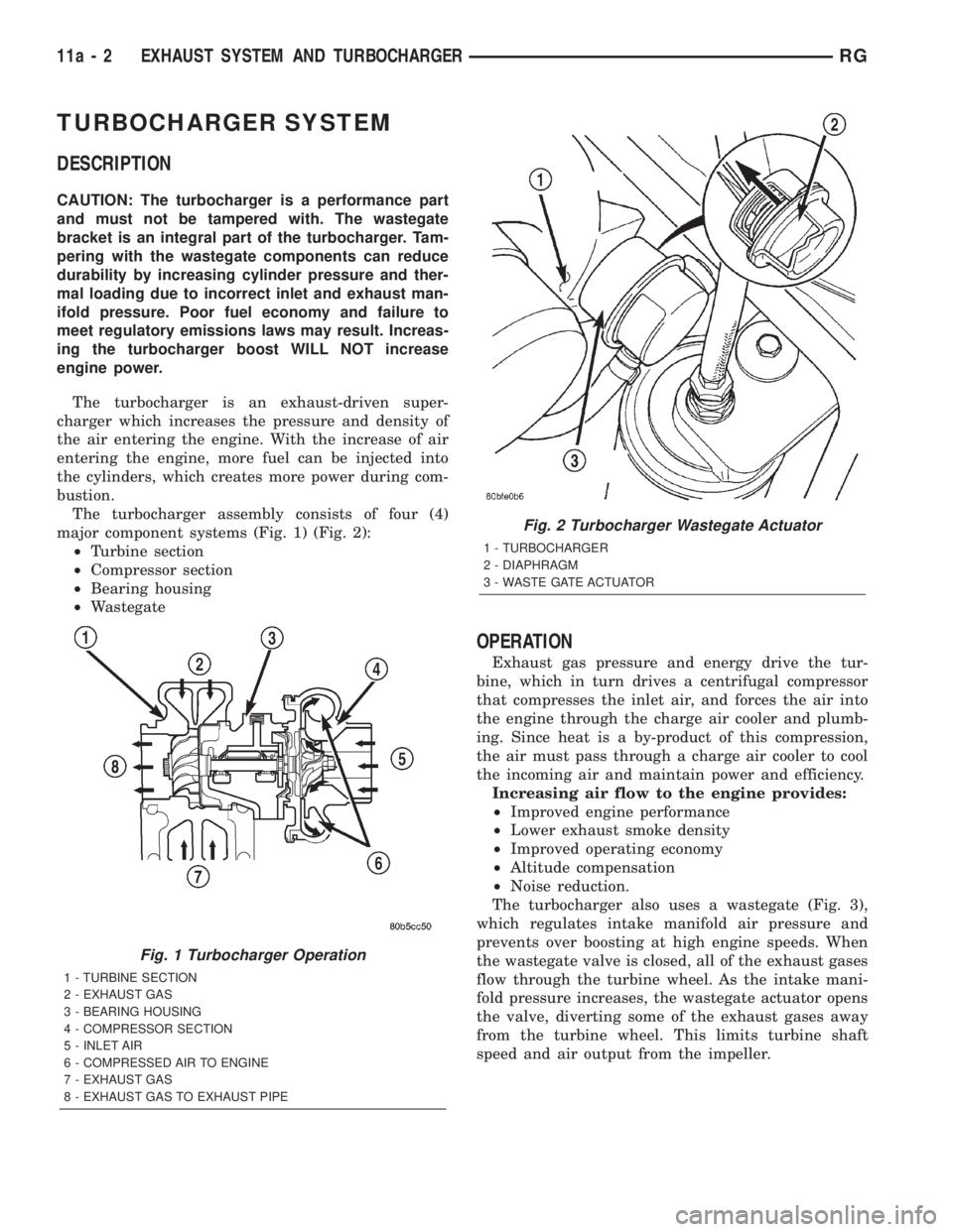
The turbocharger assembly consists of four (4)
major component systems (Fig. 1) (Fig. 2):
²Turbine section
²Compressor section
²Bearing housing
²Wastegate
OPERATION
Exhaust gas pressure and energy drive the tur-
bine, which in turn drives a centrifugal compressor
that compresses the inlet air, and forces the air into
the engine through the charge air cooler and plumb-
ing. Since heat is a by-product of this compression,
the air must pass through a charge air cooler to cool
the incoming air and maintain power and efficiency.
Increasing air flow to the engine provides:
²Improved engine performance
²Lower exhaust smoke density
²Improved operating economy
²Altitude compensation
²Noise reduction.
The turbocharger also uses a wastegate (Fig. 3),
which regulates intake manifold air pressure and
prevents over boosting at high engine speeds. When
the wastegate valve is closed, all of the exhaust gases
flow through the turbine wheel. As the intake mani-
fold pressure increases, the wastegate actuator opens
the valve, diverting some of the exhaust gases away
from the turbine wheel. This limits turbine shaft
speed and air output from the impeller.
Fig. 1 Turbocharger Operation
1 - TURBINE SECTION
2 - EXHAUST GAS
3 - BEARING HOUSING
4 - COMPRESSOR SECTION
5 - INLET AIR
6 - COMPRESSED AIR TO ENGINE
7 - EXHAUST GAS
8 - EXHAUST GAS TO EXHAUST PIPE
Fig. 2 Turbocharger Wastegate Actuator
1 - TURBOCHARGER
2 - DIAPHRAGM
3 - WASTE GATE ACTUATOR
11a - 2 EXHAUST SYSTEM AND TURBOCHARGERRG
Page 2897 of 4284
FUEL INJECTOR
DESCRIPTION
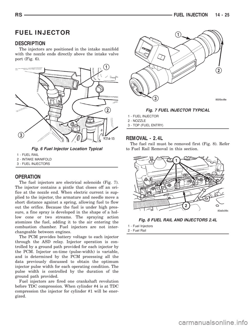
The injectors are positioned in the intake manifold
with the nozzle ends directly above the intake valve
port (Fig. 6).
OPERATION
The fuel injectors are electrical solenoids (Fig. 7).
The injector contains a pintle that closes off an ori-
fice at the nozzle end. When electric current is sup-
plied to the injector, the armature and needle move a
short distance against a spring, allowing fuel to flow
out the orifice. Because the fuel is under high pres-
sure, a fine spray is developed in the shape of a hol-
low cone or two streams. The spraying action
atomizes the fuel, adding it to the air entering the
combustion chamber. Fuel injectors are not inter-
changeable between engines.
The PCM provides battery voltage to each injector
through the ASD relay. Injector operation is con-
trolled by a ground path provided for each injector by
the PCM. Injector on-time (pulse-width) is variable,
and is determined by the PCM processing all the
data previously discussed to obtain the optimum
injector pulse width for each operating condition. The
pulse width is controlled by the duration of the
ground path provided.
Fuel injectors are fired one crankshaft revolution
before TDC compression. When cylinder #4 is at TDC
compression the injector for cylinder #1 will be ener-
gized.
REMOVAL - 2.4L
The fuel rail must be removed first (Fig. 8). Refer
to Fuel Rail Removal in this section.
Fig. 6 Fuel Injector Location Typical
1 - FUEL RAIL
2 - INTAKE MANIFOLD
3 - FUEL INJECTORS
Fig. 7 FUEL INJECTOR TYPICAL
1 - FUEL INJECTOR
2 - NOZZLE
3 - TOP (FUEL ENTRY)
Fig. 8 FUEL RAIL AND INJECTORS 2.4L
1 - Fuel Injectors
2 - Fuel Rail
RSFUEL INJECTION14-25
Page 3755 of 4284
²Ethanel content learn is takeng place and the
ethenal used once flag is set
SuspendÐThe Task Manager does not mature a
catalyst fault if any of the following are present:
²Oxygen Sensor Monitor, Priority 1
²Upstream Oxygen Sensor Heater, Priority 1
²EGR Monitor, Priority 1
²EVAP Monitor, Priority 1
²Fuel System Monitor, Priority 2
²Misfire Monitor, Priority 2
DESCRIPTION - VEHICLE EMISSION CONTROL
INFORMATION LABEL
All models have a Vehicle Emission Control Infor-
mation (VECI) Label. Chrysler permanently attaches
the label in the engine compartment. It cannot be
removed without defacing information and destroying
the label.
The label contains the vehicle's emission specifica-
tions and vacuum hose routings. All hoses must be
connected and routed according to the label.
DESCRIPTION - TRIP DEFINITION
A ªTripº means vehicle operation (following an
engine-off period) of duration and driving mode such
that all components and systems are monitored at
least once by the diagnostic system. The monitors
must successfully pass before the PCM can verify
that a previously malfunctioning component is meet-
ing the normal operating conditions of that compo-
nent. For misfire or fuel system malfunction, the
MIL may be extinguished if the fault does not recur
when monitored during three subsequent sequential
driving cycles in which conditions are similar to
those under which the malfunction was first deter-
mined.
Anytime the MIL is illuminated, a DTC is stored.
The DTC can self erase only when the MIL has been
extinguished. Once the MIL is extinguished, the
PCM must pass the diagnostic test for the most
recent DTC for 40 warm-up cycles (80 warm-up
cycles for the Fuel System Monitor and the Misfire
Monitor) . A warm-up cycle can best be described by
the following:
²The engine must be running
²A rise of 40ÉF in engine temperature must occur
from the time when the engine was started
²Engine coolant temperature must reach at least
160ÉF
²A ªdriving cycleº that consists of engine start up
and engine shut off.
Once the above conditions occur, the PCM is con-
sidered to have passed a warm-up cycle. Due to the
conditions required to extinguish the MIL and erase
the DTC, it is most important that after a repair hasbeen made, all DTC's be erased and the repair veri-
fied.
OPERATION - NON-MONITORED CIRCUITS
The PCM does not monitor all circuits, systems
and conditions that could have malfunctions causing
driveability problems. However, problems with these
systems may cause the PCM to store diagnostic trou-
ble codes for other systems or components. For exam-
ple, a fuel pressure problem will not register a fault
directly, but could cause a rich/lean condition or mis-
fire. This could cause the PCM to store an oxygen
sensor or misfire diagnostic trouble code.
The major non-monitored circuits are listed below
along with examples of failures modes that do not
directly cause the PCM to set a DTC, but for a sys-
tem that is monitored.
FUEL PRESSURE
The fuel pressure regulator controls fuel system
pressure. The PCM cannot detect a clogged fuel
pump inlet filter, clogged in-line fuel filter, or a
pinched fuel supply or return line. However, these
could result in a rich or lean condition causing the
PCM to store an oxygen sensor or fuel system diag-
nostic trouble code.
SECONDARY IGNITION CIRCUIT
The PCM cannot detect an inoperative ignition coil,
fouled or worn spark plugs, ignition cross firing, or
open spark plug cables.
CYLINDER COMPRESSION
The PCM cannot detect uneven, low, or high engine
cylinder compression.
EXHAUST SYSTEM
The PCM cannot detect a plugged, restricted or
leaking exhaust system. It may set a EGR or Fuel
system fault or O2S.
FUEL INJECTOR MECHANICAL MALFUNCTIONS
The PCM cannot determine if a fuel injector is
clogged, the needle is sticking or if the wrong injector
is installed. However, these could result in a rich or
lean condition causing the PCM to store a diagnostic
trouble code for either misfire, an oxygen sensor, or
the fuel system.
EXCESSIVE OIL CONSUMPTION
Although the PCM monitors engine exhaust oxygen
content when the system is in closed loop, it cannot
determine excessive oil consumption.
THROTTLE BODY AIR FLOW
The PCM cannot detect a clogged or restricted air
cleaner inlet or filter element.
RSEMISSIONS CONTROL25-5
EMISSIONS CONTROL (Continued)
Page 3799 of 4284
Once the auto shutdown and fuel pump relays
have been energized, the PCM determines the fuel
injector pulse width based on the following:
± engine coolant temperature
± manifold absolute pressure
± intake air temperature
± engine revolutions
± throttle position
The PCM determines the spark advance based on
the following:
± engine coolant temperature
± crankshaft position
± intake air temperature
± manifold absolute pressure
± throttle position
Engine Warm-Up Modeþ This is an open loop
mode. The PCM adjusts injector pulse width and
controls injector synchronization by controlling the
fuel injectors' ground paths. The PCM adjusts igni-
tion timing and engine idle speed. The PCM adjusts
the idle speed by controlling the idle air control
motor.
Cruise or Idle Modeþ When the engine is at
normal operating temperature, this is a closed loop
mode.
Acceleration Modeþ This is a closed loop mode.
The PCM recognizes an increase in throttle position
and a decrease in Manifold Vacuum as engine load
increases. In response, the PCM increases the in-
jector pulse width to meet the increased load. The
A/C compressor may be de-energized for a short
period of time.
Decelerationþ This is a closed loop mode. The
PCM recognizes a decrease in throttle position and
an increase in Manifold Vacuum as engine load
decreases. In response, the PCM decreases the
injector pulse width to meet the decreased load.
Full injector shut off may be obtained during high
speed deceleration.
Wide Open Throttle Modeþ This is an open
loop mode. The throttle position sensor notifies the
PCM of a wide open throttle condition. Once a wide
open throttle is sensed, the PCM de-energizes the
A/C compressor clutch relay for 20 seconds.
3.2.5 NON-MONITORED CIRCUITS
The PCM does not monitor the following circuits,
systems, and conditions even though they could
have malfunctions that result in driveability prob-
lems. A diagnostic code may not be displayed for the
following conditions. However, problems with these
systems may cause a diagnostic code to be displayed
for other systems. For example, a fuel pressure
problem will not register a diagnostic code directly,
but could cause a rich or lean condition. This couldcause an oxygen sensor, fuel system, or misfire
monitor trouble code to be stored in the PCM.
Engine Timingþ The PCM cannot detect an
incorrectly indexed timing chain, camshaft
sprocket, or crankshaft sprocket. The PCM also
cannot detect an incorrectly indexed distributor.(*)
Fuel Pressureþ Fuel pressure is controlled by
the fuel pressure regulator. The PCM cannot detect
a clogged fuel pump inlet filter, clogged in-line filter,
or a pinched fuel supply.(*)
Fuel Injectorsþ The PCM cannot detect if a fuel
injector is clogged, the pintle is sticking, or the
wrong injectors are installed.(*)
Fuel Requirementsþ Poor quality gasoline can
cause problems such as hard starting, stalling, and
stumble. Use of methanol-gasoline blends may re-
sult in starting and driveability problems. See indi-
vidual symptoms and their definitions in Section
6.0 (Glossary of Terms).
PCM Groundsþ The PCM cannot detect a poor
system ground. However, a diagnostic trouble code
may be stored in the PCM as a result of this
condition.
Throttle Body Air Flowþ The PCM cannot
detect a clogged or restricted air cleaner inlet or
filter element.(*)
Exhaust Systemþ The PCM cannot detect a
plugged, restricted, or leaking exhaust system.(*)
Cylinder Compressionþ The PCM cannot de-
tect uneven, low, or high engine cylinder compres-
sion.(*)
Excessive Oil Consumptionþ Although the
PCM monitors the exhaust stream oxygen content
through the oxygen sensor when the system is in a
closed loop, it cannot determine excessive oil con-
sumption.
NOTE: ANY OF THESE CONDITIONS
COULD RESULT IN A RICH OR LEAN
CONDITION CAUSING AN OXYGEN SENSOR
TROUBLE CODE TO BE STORED IN THE
PCM, OR THE VEHICLE MAY EXHIBIT ONE
OR MORE OF THE DRIVEABILITY
SYMPTOMS LISTED IN THE TABLE OF
CONTENTS.
3.2.6 SKIS OVERVIEW
The Sentry Key Immobilizer System (SKIS) is
designed to prevent unauthorized vehicle opera-
tion. The system consists of a Sentry Key Immobi-
lizer Module (SKIM), ignition key(s) equipped with
a transponder chip and PCM. When the ignition
switch is turned on, the SKIM interrogates the
ignition key. If the ignition key is Valid or Invalid,
the SKIM sends a PCI Bus message to the PCM
indicating ignition key status. Upon receiving this
5
GENERAL INFORMATION