2001 CHRYSLER VOYAGER clock reset
[x] Cancel search: clock resetPage 309 of 4284

Symptom:
REAR KEYBOARD FAULT (ACTIVE)
POSSIBLE CAUSES
BCM
IGNITION SWITCH (RUN) CIRCUIT OPEN
KDB CLOCK CIRCUIT SHORTED TO VOLTAGE
KDB DATA CIRCUIT SHORTED TO GROUND
KDB DATA CIRCUIT SHORTED TO VOLTAGE
KDB CLOCK CIRCUIT SHORTED TO GROUND
KDB DATA CIRCUIT OPEN
ATC - KDB DATA CIRCUIT FAULT
KDB CLOCK CIRCUIT OPEN
ATC - KDB CLOCK CIRCUIT FAULT
REAR ATC SWITCH GROUND CIRCUIT OPEN
REAR AUTOMATIC TEMPERATURE CONTROL SWITCH
TEST ACTION APPLICABILITY
1 Turn the ignition off.
Disconnect the Rear Automatic Temperature Control Switch harness connector.
Measure the resistance of the Rear ATC Switch Ground circuit.
Is the resistance below 5.0 ohms?All
Ye s®Go To 2
No®Repair the Rear ATC Switch Ground circuit for an open.
With the DRBIIIt, reset the ATC after repair/replacement is
complete.
Perform BODY VERIFICATION TEST - VER 1.
2 Turn the ignition off.
Disconnect the Rear Automatic Temperature Control Switch harness connector.
Turn the ignition on.
Measure the voltage of the Ignition Switch (Run) circuit.
Is the voltage above 10.0 volts?All
Ye s®Go To 3
No®Go To 14
3 Turn the ignition off.
Disconnect the Rear Automatic Temperature Control Switch harness connector.
Turn the ignition on.
Measure the voltage of the KDB Data circuit.
Is the voltage above 10.0 volts?All
Ye s®Go To 4
No®Go To 11
280
AUTOMATIC TEMPERATURE CONTROL
Page 310 of 4284

TEST ACTION APPLICABILITY
4 Turn the ignition off.
Disconnect the Rear Automatic Temperature Control Switch harness connector.
Disconnect the ATC C2 harness connector.
Turn the ignition on.
Measure the voltage of the KDB Data circuit.
Is the voltage above 1.0 volt?All
Ye s®Repair the KDB Data circuit for a short to voltage.
With the DRBIIIt, reset the ATC after repair/replacement is
complete.
Perform BODY VERIFICATION TEST - VER 1.
No®Go To 5
5 Turn the ignition off.
Disconnect the Rear Automatic Temperature Control Switch harness connector.
Use Scope input cable CH7058, Cable to Probe adapter CH7062, and the red and
black test probes.
Connect the scope input cable to the channel one connector on the DRB. Attach the
red and black leads and the cable to probe adapter to the scope input cable.
Select Lab Scope.
Select Live.
Select 12 volt square wave.
Press F2 for Scope.
Press F2 and use the arrows to set the voltage range to 20 volts, the Offset to 4.0, and
the Probe to x10. Press F2 again and set the divisions to 40ms/Div, then press F2
again when complete.
Connect the Black lead to the chassis ground. Connect the Red lead to the KDB Clock
circuit in the Rear Automatic Temperature Control Switch harness connector.
Turn the ignition on.
Observe the voltage display on the DRB Lab Scope.
NOTE: The lab scope pattern should look similar to the example given in the
support material and cycle from approximately 0 volts to 8.0 volts.
Did the lab scope pattern and voltage react as noted above?All
Ye s®Go To 6
No®Go To 7
6 If there are no possible causes remaining, view repair. All
Repair
Replace the Rear Automatic Temperature Control Switch.
With the DRBIIIt, reset the ATC after repair/replacement is
complete.
Perform BODY VERIFICATION TEST - VER 1.
7 Turn the ignition off.
Disconnect the Rear Automatic Temperature Control Switch harness connector.
Disconnect the ATC C2 harness connector.
Turn the ignition on.
Measure the voltage of the KDB Clock circuit.
Is the voltage above 1.0 volt?All
Ye s®Repair the KDB Clock circuit for a short to voltage.
With the DRBIIIt, reset the ATC after repair/replacement is
complete.
Perform BODY VERIFICATION TEST - VER 1.
No®Go To 8
281
AUTOMATIC TEMPERATURE CONTROL
REAR KEYBOARD FAULT (ACTIVE) ÐContinued
Page 311 of 4284

TEST ACTION APPLICABILITY
8 Turn the ignition off.
Disconnect the Rear Automatic Temperature Control Switch harness connector.
Disconnect the ATC C2 harness connector.
Measure the resistance between ground and the KDB Clock circuit.
Is the resistance above 100k ohms?All
Ye s®Go To 9
No®Repair the KDB Clock circuit for a short to ground.
With the DRBIIIt, reset the ATC after repair/replacement is
complete.
Perform BODY VERIFICATION TEST - VER 1.
9 Turn the ignition off.
Disconnect the Rear Automatic Temperature Control Switch harness connector.
Disconnect the ATC C2 harness connector.
Measure the resistance of the KDB Clock circuit.
Is the resistance below 5.0 ohms?All
Ye s®Go To 10
No®Repair the KDB Clock circuit for an open.
With the DRBIIIt, reset the ATC after repair/replacement is
complete.
Perform BODY VERIFICATION TEST - VER 1.
10 If there are no possible causes remaining, view repair. All
Repair
Replace the ATC.
With the DRBIIIt, reset the ATC after repair/replacement is
complete.
Perform BODY VERIFICATION TEST - VER 1.
11 Turn the ignition off.
Disconnect the Rear Automatic Temperature Control Switch harness connector.
Disconnect the ATC C2 harness connector.
Measure the resistance between ground and the KDB Data circuit.
Is the resistance above 100k ohms?All
Ye s®Go To 12
No®Repair the KDB Data circuit for a short to ground.
With the DRBIIIt, reset the ATC after repair/replacement is
complete.
Perform BODY VERIFICATION TEST - VER 1.
12 Turn the ignition off.
Disconnect the Rear Automatic Temperature Control Switch harness connector.
Disconnect the ATC C2 harness connector.
Measure the resistance of the KDB Data circuit.
Is the resistance below 5.0 ohms?All
Ye s®Go To 13
No®Repair the KDB Data circuit for an open.
With the DRBIIIt, reset the ATC after repair/replacement is
complete.
Perform BODY VERIFICATION TEST - VER 1.
282
AUTOMATIC TEMPERATURE CONTROL
REAR KEYBOARD FAULT (ACTIVE) ÐContinued
Page 1814 of 4284

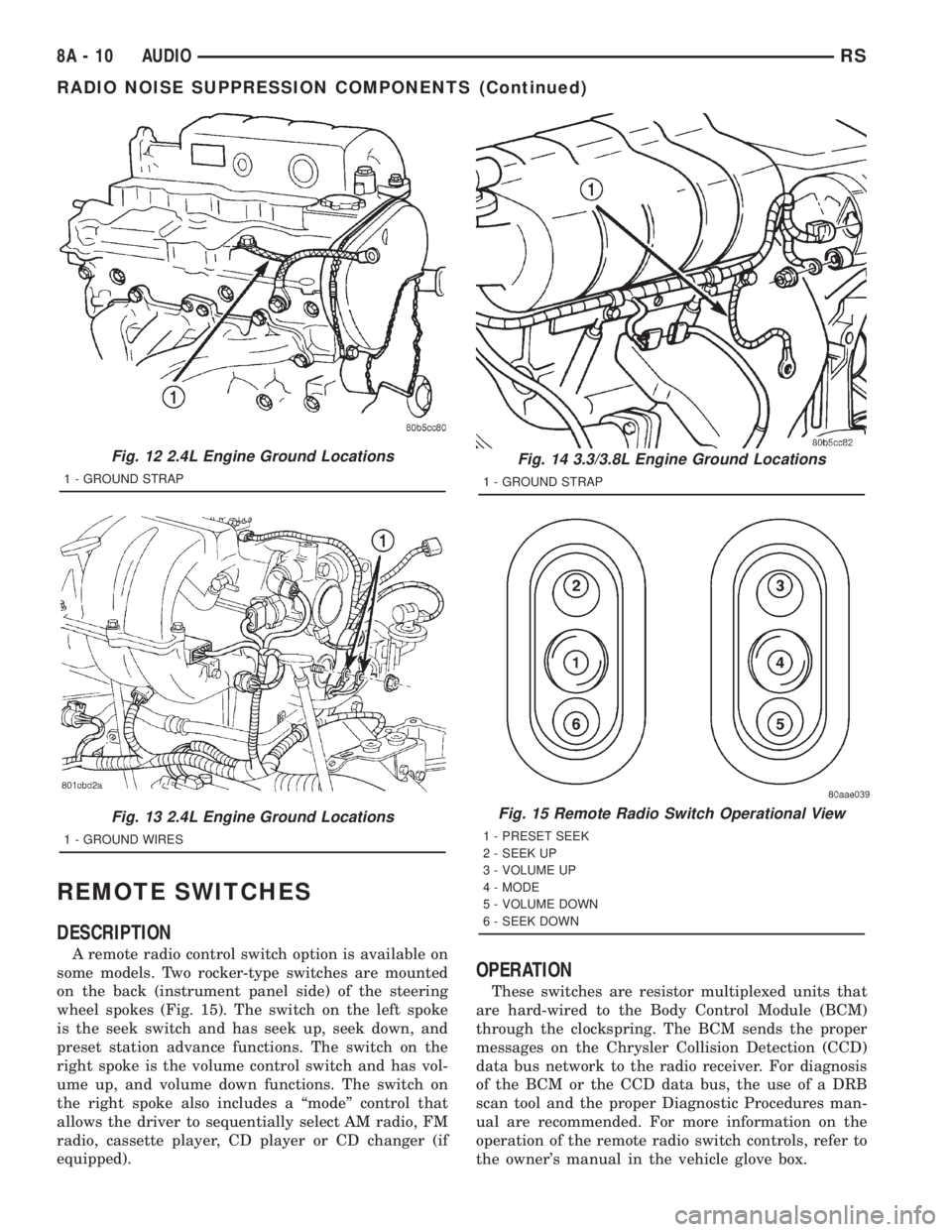
REMOTE SWITCHES
DESCRIPTION
A remote radio control switch option is available on
some models. Two rocker-type switches are mounted
on the back (instrument panel side) of the steering
wheel spokes (Fig. 15). The switch on the left spoke
is the seek switch and has seek up, seek down, and
preset station advance functions. The switch on the
right spoke is the volume control switch and has vol-
ume up, and volume down functions. The switch on
the right spoke also includes a ªmodeº control that
allows the driver to sequentially select AM radio, FM
radio, cassette player, CD player or CD changer (if
equipped).
OPERATION
These switches are resistor multiplexed units that
are hard-wired to the Body Control Module (BCM)
through the clockspring. The BCM sends the proper
messages on the Chrysler Collision Detection (CCD)
data bus network to the radio receiver. For diagnosis
of the BCM or the CCD data bus, the use of a DRB
scan tool and the proper Diagnostic Procedures man-
ual are recommended. For more information on the
operation of the remote radio switch controls, refer to
the owner's manual in the vehicle glove box.
Fig. 12 2.4L Engine Ground Locations
1 - GROUND STRAP
Fig. 13 2.4L Engine Ground Locations
1 - GROUND WIRES
Fig. 14 3.3/3.8L Engine Ground Locations
1 - GROUND STRAP
Fig. 15 Remote Radio Switch Operational View
1 - PRESET SEEK
2 - SEEK UP
3 - VOLUME UP
4 - MODE
5 - VOLUME DOWN
6 - SEEK DOWN
8A - 10 AUDIORS
RADIO NOISE SUPPRESSION COMPONENTS (Continued)
Page 1954 of 4284

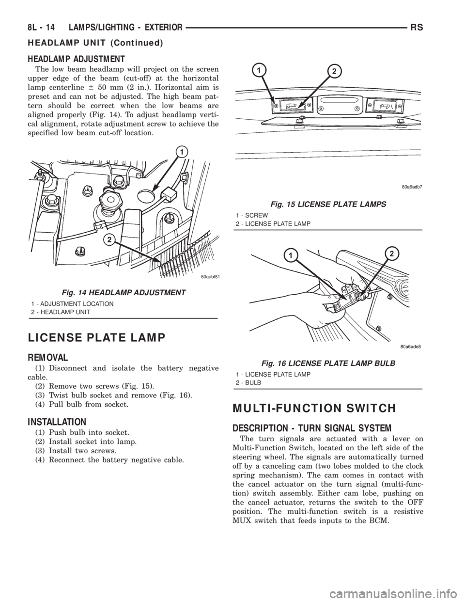
HEADLAMP ADJUSTMENT
The low beam headlamp will project on the screen
upper edge of the beam (cut-off) at the horizontal
lamp centerline650 mm (2 in.). Horizontal aim is
preset and can not be adjusted. The high beam pat-
tern should be correct when the low beams are
aligned properly (Fig. 14). To adjust headlamp verti-
cal alignment, rotate adjustment screw to achieve the
specified low beam cut-off location.
LICENSE PLATE LAMP
REMOVAL
(1) Disconnect and isolate the battery negative
cable.
(2) Remove two screws (Fig. 15).
(3) Twist bulb socket and remove (Fig. 16).
(4) Pull bulb from socket.
INSTALLATION
(1) Push bulb into socket.
(2) Install socket into lamp.
(3) Install two screws.
(4) Reconnect the battery negative cable.
MULTI-FUNCTION SWITCH
DESCRIPTION - TURN SIGNAL SYSTEM
The turn signals are actuated with a lever on
Multi-Function Switch, located on the left side of the
steering wheel. The signals are automatically turned
off by a canceling cam (two lobes molded to the clock
spring mechanism). The cam comes in contact with
the cancel actuator on the turn signal (multi-func-
tion) switch assembly. Either cam lobe, pushing on
the cancel actuator, returns the switch to the OFF
position. The multi-function switch is a resistive
MUX switch that feeds inputs to the BCM.
Fig. 14 HEADLAMP ADJUSTMENT
1 - ADJUSTMENT LOCATION
2 - HEADLAMP UNIT
Fig. 15 LICENSE PLATE LAMPS
1 - SCREW
2 - LICENSE PLATE LAMP
Fig. 16 LICENSE PLATE LAMP BULB
1 - LICENSE PLATE LAMP
2 - BULB
8L - 14 LAMPS/LIGHTING - EXTERIORRS
HEADLAMP UNIT (Continued)
Page 1972 of 4284

more faulty electronic modules in the vehicle, or from
a faulty PCI data bus. The use of a DRB IIItscan
tool and the proper Diagnostic Procedures manual
are required for further diagnosis.
NOTE: If the compass functions, but accuracy is
suspect, it may be necessary to perform a variation
adjustment. This procedure allows the compass
unit to accommodate variations in the earth's mag-
netic field strength, based on geographic location.
Refer to Compass Variation Adjustment in the Ser-
vice Procedures section of this group.
NOTE: If the compass reading displays dashes, and
only ªCALº appears in the display, demagnetizing
may be necessary to remove excessive residual
magnetic fields from the vehicle. Refer to Compass
Demagnetizing in the Service Procedures section of
this group.
STANDARD PROCEDURE - READING/
COURTESY LAMP REPLACEMENT
(1) Open hood, disconnect and isolate the negative
battery cable remote terminal from the remote bat-
tery post.
(2) Remove the reading/courtesy lamp lens. Using
a trim stick, gently pry the forward edge of the read-
ing/courtesy lamp lens outward.
(3) Remove the reading/courtesy lamp socket from
the overhead console. Rotate the reading/courtesy
lamp socket one quarter turn counter clockwise.
(4) Remove the lamp and socket assembly.
(5) Reverse the above procedure to install.
STANDARD PROCEDURE - COMPASS
CALIBRATION
CAUTION: Do not place any external magnets, such
as magnetic roof mount antennas, in the vicinity of
the compass. Do not use magnetic tools when ser-
vicing the overhead console.
The electronic compass unit features a self-cali-
brating design, which simplifies the calibration pro-
cedure. This feature automatically updates the
compass calibration while the vehicle is being driven.
This allows the compass unit to compensate for small
changes in the residual magnetism that the vehicle
may acquire during normal use. If the compass read-
ings appear to be erratic or out of calibration, per-
form the following calibration procedure. Also, new
service replacement Electronic Modules (EVIC,
CMTC, CT) must have their compass calibrated
using this procedure. Do not attempt to calibrate the
compass near large metal objects such as other vehi-cles, large buildings, or bridges; or, near overhead or
underground power lines.
NOTE: Whenever the compass is calibrated manu-
ally, the variance number must also be reset. Refer
to Compass Variation Adjustment in this group.
Calibrate the compass manually as follows:
(1) Turn the ignition switch to the On position. If
the compass/thermometer data is not currently being
displayed, momentarily depress and release the C/T
push button to reach the compass/thermometer dis-
play.
(2) On Electronic Vehicle Information Center
(EVIC) and Compass Mini-Trip Computer (CMTC)
equipped vehicles depress the Reset push button and
hold the button down until ªCALº appears in the dis-
play. This takes about ten seconds, and appears
about five seconds after ªVAR = XXº is displayed. On
Compass Temperature Module (CT) equipped vehicles
depress the C/T push button and US/M push button
down until ªCALº appears in the display. This takes
about ten seconds, and appears about five seconds
after ªVAR = XXº is displayed.
(3) Release the push button(s).
(4) Drive the vehicle on a level surface, away from
large metal objects and power lines, through three or
more complete circles at between five and eight kilo-
meters-per-hour (three and five miles-per-hour) in
not less than 48 seconds. The ªCALº message will
disappear from the display to indicate that the com-
pass is now calibrated.
NOTE: If the ªCALº message remains in the display,
either there is excessive magnetism near the com-
pass, or the unit is faulty. Repeat the calibration
procedure one more time.
NOTE: If the wrong direction is still indicated in the
compass display, the area selected for calibration
may be too close to a strong magnetic field. Repeat
the calibration procedure in another location.
STANDARD PROCEDURE - COMPASS
DEMAGNETIZING
A degaussing tool (Special Tool 6029) is used to
demagnetize, or degauss, the overhead console for-
ward mounting screw and the roof panel above the
overhead console. Equivalent units must be rated as
continuous duty for 110/115 volts and 60 Hz. They
must also have a field strength of over 350 gauss at 7
millimeters (0.25 inch) beyond the tip of the probe.
To demagnetize the roof panel and the overhead
console forward mounting screw, proceed as follows:
8M - 4 OVERHEAD CONSOLERS
OVERHEAD CONSOLE (Continued)