2001 CHRYSLER VOYAGER glove box
[x] Cancel search: glove boxPage 3373 of 4284
DIAGNOSIS AND TESTING - TIRE WEAR
PATTERNS
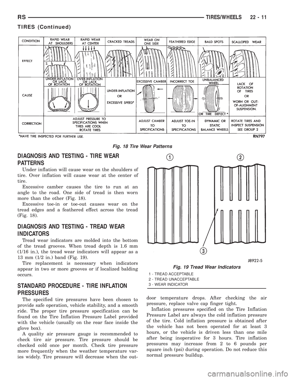
Under inflation will cause wear on the shoulders of
tire. Over inflation will cause wear at the center of
tire.
Excessive camber causes the tire to run at an
angle to the road. One side of tread is then worn
more than the other (Fig. 18).
Excessive toe-in or toe-out causes wear on the
tread edges and a feathered effect across the tread
(Fig. 18).
DIAGNOSIS AND TESTING - TREAD WEAR
INDICATORS
Tread wear indicators are molded into the bottom
of the tread grooves. When tread depth is 1.6 mm
(1/16 in.), the tread wear indicators will appear as a
13 mm (1/2 in.) band (Fig. 19).
Tire replacement is necessary when indicators
appear in two or more grooves or if localized balding
occurs.
STANDARD PROCEDURE - TIRE INFLATION
PRESSURES
The specified tire pressures have been chosen to
provide safe operation, vehicle stability, and a smooth
ride. The proper tire pressure specification can be
found on the Tire Inflation Pressure Label provided
with the vehicle (usually on the rear face inside the
glove box).
A quality air pressure gauge is recommended to
check tire air pressure. Tire pressure should be
checked cold once per month. Check tire pressure
more frequently when the weather temperature var-
ies widely. Tire pressure will decrease when the out-door temperature drops. After checking the air
pressure, replace valve cap finger tight.
Inflation pressures specified on the Tire Inflation
Pressure Label are always the cold inflation pressure
of the tire. Cold inflation pressure is obtained after
the vehicle has not been operated for at least 3
hours, or the vehicle is driven less than one mile
after being inoperative for 3 hours. Tire inflation
pressures may increase from 2 to 6 pounds per
square inch (psi) during operation. Do not reduce this
normal pressure buildup.
Fig. 18 Tire Wear Patterns
Fig. 19 Tread Wear Indicators
1 - TREAD ACCEPTABLE
2 - TREAD UNACCEPTABLE
3 - WEAR INDICATOR
RSTIRES/WHEELS22-11
TIRES (Continued)
Page 3582 of 4284
INSTRUMENT PANEL
TABLE OF CONTENTS
page page
CLUSTER BEZEL
REMOVAL.............................202
INSTALLATION..........................202
CUP HOLDER
REMOVAL.............................202
INSTALLATION..........................202
GLOVE BOX
REMOVAL.............................203
INSTALLATION..........................203
GLOVE BOX LATCH
REMOVAL.............................203
INSTALLATION..........................203
GLOVE BOX LATCH STRIKER
REMOVAL.............................203
INSTALLATION..........................203
INSTRUMENT PANEL ASSEMBLY
REMOVAL.............................203
INSTALLATION..........................204
INSTRUMENT PANEL CENTER BEZEL
REMOVAL.............................205
INSTALLATION..........................205INSTRUMENT PANEL END COVER
REMOVAL.............................205
INSTALLATION..........................205
INSTRUMENT PANEL TOP COVER
REMOVAL.............................205
INSTALLATION..........................206
KNEE BLOCKER REINFORCEMENT
REMOVAL.............................206
INSTALLATION..........................206
LOWER CONSOLE
REMOVAL.............................206
INSTALLATION..........................206
LOWER INSTRUMENT PANEL
REMOVAL.............................206
INSTALLATION..........................206
LOWER STEERING COLUMN COVER
REMOVAL.............................206
INSTALLATION..........................206
OVER STEERING COLUMN COVER
REMOVAL.............................207
INSTALLATION..........................207
CLUSTER BEZEL
REMOVAL
(1) Disconnect and isolate the battery negative
cable.
(2) Remove Over Steering Column Bezel by lifting
it straight up with a firm pull.
(3) Remove the four bezel attaching screws.
(4) Tilt the steering column in the full down posi-
tion.
(5) Pull rearward on the cluster bezel and remove.
INSTALLATION
(1) Manuever cluster bezel over steering column
and into position.
(2) Install the four bezel attaching screws.
(3) Install the Over Steering Column Bezel by
positioning it over the retaining slots and firmly
snapping it into place.
(4) Connect the battery negative cable.
CUP HOLDER
REMOVAL
(1) Remove the cup holder. Pull the cup holder out
and depress the tang in the middle back and pull
rearward to release the cup holder.
(2) Remove the screw access cover from the bottom
of the center bezel.
(3) Using a trim stick (special tool #C-4755) or
equivalent, gently pry out on the edge of the instru-
ment panel center bezel. Hang off to the side leaving
the accessory switches connected.
(4) Remove the cup holder assembly attaching
screws and pull the assembly rearward to disengage
the rear guide studs from instrument panel.
(5) Remove the cup holder track assembly.
INSTALLATION
(1) Install the cup holder track assembly.
(2) Place the cup holder track assembly into posi-
tion and slide into opening in instrument panel until
the rear guide struts snap into place. Install the cup
holder assembly attaching screws.
(3) Install the center bezel.
(4) Install the screw access cover from the bottom
of the center bezel.
23 - 202 INSTRUMENT PANELRS
Page 3583 of 4284
(5) Install the cup holder. Align the cup holder
assembly with the track and firmly slide shut to
engage retaining tang.
GLOVE BOX
REMOVAL
(1) Open glove box.
(2) Push in on sides of glove box bin and lower
door.
(3) Pivot glove box downward and disengage hinge
hooks from instrument panel.
(4) Remove glove box.
INSTALLATION
(1) Place glove box in position.
(2) Engage hinge hooks into instrument panel and
pivot glove box upward.
(3) Push in sides of glove box bin and snap glove
box assembly into instrument panel.
(4) Close glove box door.
GLOVE BOX LATCH
REMOVAL
(1) Open glove box.
(2) Push in on sides of glove box bin and lower
door.
(3) Pivot glove box downward and disengage hinge
hooks from instrument panel.
(4) Remove glove box.
(5) Remove the assembly screws.
(6) Disassemble the glove box.
(7) Separate the latch from the glove box assembly.
INSTALLATION
(1) Install the latch onto the glove box assembly.
(2) Assemble the glove box.
(3) Install the assembly screws.
(4) Engage hinge hooks into instrument panel and
pivot glove box upward.
(5) Push in sides of glove box bin and snap glove
box assembly into instrument panel.
(6) Close glove box door.
GLOVE BOX LATCH STRIKER
REMOVAL
(1) Open glove box door.
(2) Remove screws holding lock striker to instru-
ment panel.
(3) Remove glove box latch striker.
INSTALLATION
(1) Install the glove box latch striker.
(2) Install the screws holding latch striker to
instrument panel.
(3) Close glove box door.
INSTRUMENT PANEL
ASSEMBLY
REMOVAL
(1) Disconnect and isolate the battery negative
cable.
(2) Remove the lower console:
(a) Remove six retaining screws.
(b) Pull rearward and disconnect the auxiliary
power outlet.
(c) Remove lower console from vehicle.
(3) Remove the bolts holding the lower supports to
the instrument panel frame.
(4) Remove the bolts holding the lower supports to
the floor pan.
(5) Disconnect the wire connectors from the Pas-
senger Airbag.
(6) Remove the two screws to each right and left
cowl trim covers.
(7) Remove the both left and right side A-pillar
trim covers using a trim stick (special tool #C-4755)
or equivalent gently pry out on the trim covers and
remove.
(8) Remove the glove box:
(a) Push in on sides of glove box bin and lower
door.
(b) Pivot glove box downward and disengage
hinge hooks from instrument panel.
(c) Remove glove box from vehicle.
(9) Disconnect the antenna lead connector from
behind the glove box.
(10) Remove the four screws to the lower steering
column cover.
(11) Remove the eight screws to the plastic knee
blocker reinforcement.
(12) Unclip the Data Link Connector (DLC) from
the instrument panel reinforcement.
(13) Remove one screw to the left side instrument
panel silencer and remove.
(14) Disconnect the left side wiring:
(a) Brake switch.
(b) Main bulkhead connector.
(c) Five harness connectors.
(d) Driver airbag connector.
(15) Remove the two screws to the hood release
handle.
(16) Remove five screws to the left under column
instrument panel reinforcement brace and remove.
RSINSTRUMENT PANEL23 - 203
CUP HOLDER (Continued)
Page 3584 of 4284
(17) Remove the two steering column shroud
retaining screws. Separate the shrouds and remove
from vehicle.
(18) Disconnect the steering column wiring. There
are seven connectors and then unclip the harness
from the column.
(19) Disconnect the ORC harness connector.
(20) Remove the four nuts retaining the steering
column and lower to the floor.
(21) Remove the four nuts attaching the instru-
ment panel to the brake pedal support bracket.
(22) Loosen the left side roll down bolt.
(23) Remove the left side A-pillar retaining bolts.
There are two 13 mm bolts and one 10 mm bolt.
(24) If equipped with a mechanical transmission
range indicator:
(a) Remove the indicator cable loop.
(b) Remove the clip holding gear shift cable end
to the gear selector adapter.
(c) Pull the cable end from gear selector.
(d) Disconnect the clip for the indicator cable
and guide tube from the shift cable bracket and
move out of the way.
(25) Remove the instrument panel top cover. Using
a trim stick or equivalent, gently pry up on the front
edge of the top cover, pull rearward and remove from
vehicle.
(26) Disconnect the right side wire connectors from
the HVAC behind the glove box area and the two
antenna connectors behind the glove box hinge.
(27) Remove the right end cover by pulling out-
board.
(28) Remove the right side A-pillar retaining bolts.
There are two 13 mm bolts and one 10 mm bolt.
(29) Loosen the right side roll down bolt.
(30) Disconnect the two front window defroster
grid wire connectors. One on each side of vehicle.
(31) Remove both the left and right power mirrors:
(a) Using a trim stick or equivalent, gently pry
out on mirror trim cover.
(b) Open door and remove the three torx retain-
ing screws.
(c) Disconnect the wire connector and remove
mirror from the vehicle.
(32) Feed power mirror wire harness inboard
through the A-pillar.
(33) Remove the bolts holding the instrument
panel frame to the dash panel below windshield
opening.
(34) With the help of an assistant remove the
instrument panel from vehicle. Lift the instrument
panel up off the HVAC so you won't damage the seal-
ing surface of the distribution duct.
If the instrument panel is being replaced, transfer
all parts to the new instrument panel assembly.INSTALLATION
(1) With the help of an assistant place the instru-
ment panel into vehicle on roll down bolts. As you
roll the instrument panel up, lift the instrument
panel up so the duct work does not bind or bend and
you can set it down on the HVAC housing to get the
proper seal at the distribution duct. Get one bolt
started in the dash panel.
(2) Install the bolts holding the instrument panel
frame to the dash panel below windshield opening.
(3) Feed power mirror wire harness outboard
through the A-pillar.
(4) Install both the left and right power mirrors:
(a) Connect the wire connector and install the
mirror onto the vehicle.
(b) Install the three torx retaining screws.
(c) Using a firm push, snap the mirror trim
cover into place.
(5) Connect the two front window defroster grid
wire connectors. One on each side of vehicle.
(6) Tighten the right side roll down bolt.
(7) Install the right side A-pillar retaining bolts.
There are two 13 mm bolts and one 10 mm bolt.
(8) Install the right end cover. Position over retain-
ing slots and firmly snap into place.
(9) Connect the right side wire connectors to the
HVAC behind the glove box area and the two
antenna connectors behind the glove box hinge.
(10) Install the instrument panel top cover. Slide
the front edge of the top cover toward dash panel,
and firmly snap down the rear edge of the to cover to
engage clips.
(11) If equipped with a mechanical transmission
range indicator:
(a) Connect the clip for the indicator cable and
guide tube to the shift cable bracket.
(b) Install the cable end to the gear selector.
(c) Install the clip holding the gear shift cable
end to the gear selector adapter.
(d) Install the indicator cable loop.
(12) Install the left side A-pillar retaining bolts.
There are two 13 mm bolts and one 10 mm bolt.
(13) Tighten the left side roll down bolt.
(14) Install the four nuts attaching the instrument
panel to the brake pedal support bracket.
(15) Install the four nuts retaining the steering
column and lower to the floor.
(16) Connect the ORC harness connector.
(17) Connect the steering column wiring. There
are seven connectors and then clip the harness to the
column.
(18) Connect the shrouds and install the two steer-
ing column shroud retaining screws.
(19) Install five screws to the left under column
instrument panel reinforcement brace.
23 - 204 INSTRUMENT PANELRS
INSTRUMENT PANEL ASSEMBLY (Continued)
Page 3585 of 4284
(20) Install the two screws to the hood release
handle.
(21) Connect the left side wiring:
(a) Brake switch.
(b) Main bulkhead connector.
(c) Five harness connectors.
(d) Driver airbag connector.
(22) Install one screw to the left side instrument
panel silencer.
(23) Clip the Data Link Connector (DLC) to the
instrument panel reinforcement.
(24) Install the eight screws to the plastic knee
blocker reinforcement.
(25) Install the four screws to the lower steering
column cover.
(26) Install the glove box:
(a) Install glove box into the vehicle. Line up the
hinges and firmly snap together.
(b) Push in on sides of glove box bin and raise
door.
(27) Install the both left and right side A-pillar
trim covers. Position trim cover over slots and firmly
snap into place.
(28) Install the two screws to each right and left
cowl trim covers.
(29) Connect the wire connectors to the Passenger
Airbag.
(30) Install the bolts holding the lower supports to
the floor pan.
(31) Install the bolts holding the lower supports to
the instrument panel frame.
(32) Install the lower console:
(a) Install lower console to vehicle.
(b) Connect the auxiliary power outlet.
(c) Install the six retaining screws.
(33) Connect the battery negative cable.
INSTRUMENT PANEL CENTER
BEZEL
REMOVAL
(1) Disconnect and isolate the battery negative
cable.
(2) Remove cup holder. Refer to Body, Instrument
Panel, Cup Holder, Removal.
(3) Insert the trim stick (special tool #C-4755) or
equivalent between access cover and center bezel.
(4) Carefully pry the access cover from the instru-
ment panel.
(5) Remove the cup holder track. Refer to Body,
Instrument Panel, Cup Holder, Removal.
(6) Using a trim stick or equivalent, gently pry out
on the edge of the instrument panel center bezel and
pull outward.(7) Disconnect the wire connectors to the accessory
switches and HVAC control.
(8) Remove the instrument panel center bezel from
the vehicle.
INSTALLATION
(1) Install the instrument panel center bezel from
the vehicle.
(2) Connect the wire connectors to the accessory
switches and HVAC control.
(3) Position the center bezel over the retaining
slots and firmly snap the instrument panel center
bezel into place.
(4) Install the cup holder track. Refer to Body,
Instrument Panel, Cup Holder, Installation.
(5) Position the center bezel over the retaining
slots and firmly snap into place.
(6) Install cup holder. Refer to Body, Instrument
Panel, Cup Holder, Installation.
(7) Connect the battery negative cable.
INSTRUMENT PANEL END
COVER
REMOVAL
(1) Open passenger side front door.
(2) Place fingers in end cover grille, and with a
firm outboard pulling motion, disengage clips holding
end cover to instrument panel.
INSTALLATION
(1) Position end cover over retaining slots and
firmly snap into place.
(2) Close passenger side front door.
INSTRUMENT PANEL TOP
COVER
REMOVAL
(1) Remove A-pillar trim. Using a trim stick (spe-
cial tool #C-4755) or equivalent, gently pry out and
remove.
(2) Using a trim stick, disengage clips holding rear
edge of top cover to instrument panel.
NOTE: The Instrument Panel Top Cover may be
hard to unsnap from the instrument panel. Be sure
not to mar, scuff, or damage the instrument panel
pad.
(3) Pull top cover rearward to disengage hooks
holding front of top cover to instrument panel.
(4) Remove top cover from vehicle.
RSINSTRUMENT PANEL23 - 205
INSTRUMENT PANEL ASSEMBLY (Continued)
Page 3586 of 4284
INSTALLATION
(1) Place instrument panel top cover in position on
vehicle.
(2) Push top cover forward to engage hooks to hold
front of top cover to instrument panel.
(3) Engage clips to hold rear edge of top cover to
instrument panel.
(4) Pull top cover rearward.
(5) Install A-pillar trim.
KNEE BLOCKER
REINFORCEMENT
REMOVAL
(1) Remove lower steering column cover. Refer to
Body, Instrument Panel, Instrument Panel Lower
Steering Column Cover, Removal.
(2) Remove screws holding knee blocker reinforce-
ment to instrument panel.
(3) Remove knee blocker reinforcement from vehi-
cle.
INSTALLATION
(1) Install the knee blocker reinforcement into
vehicle.
(2) Install the screws holding knee blocker rein-
forcement to instrument panel.
(3) Install the lower steering column cover. Refer
to Body, Instrument Panel, Instrument Panel Lower
Steering Column Cover, Installation.
LOWER CONSOLE
REMOVAL
(1) Remove screws holding the lower console to
floor bracket and instrument panel.
(2) Slide lower console rearward from around
instrument panel supports.
(3) Disconnect the auxiliary power outlet wire con-
nector (if equipped).
(4) Remove lower console from vehicle.
INSTALLATION
(1) Connect the auxiliary power outlet wire con-
nector (if equipped).
(2) Install the lower console into the vehicle.
(3) Slide console forward around instrument panel
supports.
(4) Install the screws holding lower console to floor
bracket and instrument panel.
LOWER INSTRUMENT PANEL
REMOVAL
When servicing the lower instrument panel, refer
to Body, Instrument Panel, and then the appropriate
removal procedure.
(1) Remove the right end cover.
(2) Remove the lower steering column cover.
(3) Remove the center bezel.
(4) Remove the lower console.
(5) Remove the cup holder and track.
(6) Remove the glove box.
(7) Remove the glove box latch striker.
(8) Remove the glove box lamp.
(9) Remove the eighteen screws holding the lower
instrument panel to the reinforcement frame.
(10) Remove the lower instrument panel from
vehicle.
INSTALLATION
When servicing the lower instrument panel, refer
to Body, Instrument Panel, and then the appropriate
removal procedure.
(1) Install the lower instrument panel into the
vehicle.
(2) Install the eighteen screws holding the lower
instrument panel to the reinforcement frame.
(3) Install the glove box lamp.
(4) Install the glove box latch striker.
(5) Install the glove box.
(6) Install the cup holder and track.
(7) Install the lower console.
(8) Install the center bezel.
(9) Install the lower steering column cover.
(10) Install the right end cover.
LOWER STEERING COLUMN
COVER
REMOVAL
(1) Remove the four screws holding the lower
steering column cover to instrument panel.
(2) Remove the lower steering column cover from
the vehicle.
INSTALLATION
(1) Install the lower steering column cover into the
vehicle.
(2) Install the four screws holding the lower steer-
ing column cover to instrument panel.
23 - 206 INSTRUMENT PANELRS
INSTRUMENT PANEL TOP COVER (Continued)
Page 3631 of 4284
HEATING & AIR CONDITIONING
TABLE OF CONTENTS
page page
HEATING & AIR CONDITIONING
DESCRIPTION............................1
OPERATION.............................3
DIAGNOSIS AND TESTING..................4
A/C COOL DOWN TEST...................4
A/C PERFORMANCE TEST................5
HEATER PERFORMANCE TEST............6SPECIFICATIONS.........................7
CONTROLS - FRONT......................8
CONTROLS - REAR......................30
DISTRIBUTION - FRONT...................41
DISTRIBUTION - REAR....................54
PLUMBING - FRONT......................62
PLUMBING - REAR.......................96
HEATING & AIR
CONDITIONING
DESCRIPTION - SINGLE ZONE
A single zone heating and air conditioning system
allows one temperature setting for the entire vehicle.
The full range of temperatures that the system can
produce are available by rotating the temperature
control located in control panel.
The control panel and integral computer is
mounted in the instrument panel.
DESCRIPTION - DUAL ZONE
A manual Dual Zone Heating and Air Conditioning
system allows completely independent side-to-side
tempeture control of the discharge air.
The Dual Zone Heating and Air Conditioning sys-
tem includes a dust and odor air filter. The filter ele-
ment is the same size as the air conditioning
evaporator to ensure ample capacity. A door at the
base of the heating and air conditioning housing
below the glove box provides easy access to the filter
element.
The control panel and integral computer is located
in the instrument panel.
The instrument panel mounted control and inte-
gral computer contains:
²a power button which allows the system to be
completely turned off. Contains an LED that illumi-
nates to show when the function is operational.
²rear window defogger on/off switch. Contains an
LED that illuminates to show when the function is
operational.
²slide controls for completely independent side-to-
side temperature control of the discharged air. The
full range of temperature that the system can pro-
duce in any mode is available on either side of the
vehicle by independently positioning the slide con-
trols on the instrument panel.²air recirculation on/off switch. The Recirculate
button contains an LED that illuminates to show
when the function is in operation.
²air conditioning on/off switch. The Snowflake
button contains an LED that illuminates to shown
when the function is in operation.
²rotary knob for fan speed selection.
²a rotary knob for mode control.
DESCRIPTION - MANUAL THREE ZONE
The fully adjustable Three-Zone front and rear
heating and air conditioning system allows interme-
diate seat passengers the ability to regulate air tem-
perature as well as fan speed. All controls are
identified by ISO graphic symbols.
The Three Zone Heating and Air Conditioning sys-
tem includes a dust and odor air filter. The filter ele-
ment is the same size as the air conditioning
evaporator to ensure ample capacity. A door at the
base of the heating and air conditioning housing
below the glove box provides easy access to the filter
element.
FRONT CONTROL PANEL
The front control panel and integral computer is
mounted in the instrument panel.
The instrument panel mounted control and inte-
gral computer contains:
²a power button which allows the system to be
completely turned off.
²rear window defogger on/off switch.
²slide controls for completely independent side-to-
side temperature control of the discharge air. The full
range of temperature that the system can produce in
any mode is available on either side of the vehicle by
independently positioning the slide controls on the
instrument panel.
²air recirculation button. The Recirculate button
contains an LED that illuminates to show when the
function is in operation.
RSHEATING & AIR CONDITIONING24-1
Page 3632 of 4284
²an air conditioning button that allows the com-
pressor to be turned on/off. The Snowflake button
contains an LED that illuminates to shown when the
function is in operation.
²rotary knobs for front and rear fan speed selec-
tion.
²a rotary knob for mode control.
REAR CONTROL PANEL
A rear control panel centrally mounted on the
headliner has a rotary adjustment for temperature
and fan speed control of the rear unit by intermedi-
ate seat passengers when the front control rear knob
is set to the rear position.
DESCRIPTION - THREE ZONE Automatic
Temperature Control
The Three-Zone Automatic Temperature Control
(ATC) allows occupants to select a comfort tempera-
ture, which is the perceived temperature level not
the actual passenger compartment air temperature.
The Three Zone Automatic Temperature Control
system includes a dust and odor air filter. The filter
element is the same size as the air conditioning evap-
orator to ensure ample capacity. A door at the base of
the heater and air conditioning housing below the
glove box provides easy access to the filter element.
The ATC computer utilizes integrated circuitry and
information carried on the Programmable Communi-
cations Interface (PCI) data bus network to monitor
many sensors and switch inputs throughout the vehi-
cle. In response to those inputs, the internal circuitry
and programming of the ATC computer allow it to
control electronic functions and features of the ATC
system. The inputs to the ATC computer are:
²Vehicle Speed/Engine RPM± The ATC com-
puter monitors engine RPM, vehicle speed and Man-
ifold Absolute Pressure information from the PCM.
²Coolant Temperature± ATC computer moni-
tors Coolant temperature received from the PCM and
converts it to degrees Fahrenheit.
²Ambient Temperature± ATC computer moni-
tors Ambient temperature from the Compass Mini
Trip Computer (CMTC) and converts it to degrees
Fahrenheit.
²Engine Miscellaneous Sensor Status±ATC
computer monitors A/C disable information from the
PCM.
²Refrigerant Pressure± ATC computer moni-
tors Barometric Pressure, Intake Air Temperature,
High Side Pressure and Methanol Content as broad-
cast by the PCM.
²Door Ajar Status± The ATC computer moni-
tors Driver Front Door, Passenger Front Door, Left
Rear Door, Right Rear Door and Liftgate ajar infor-
mation, as identified by the Body Control Module(BCM), to determine if all in-car temperatures should
be maintained.
²Dimming± The ATC computer monitors dim-
ming status from the BCM to determine the required
level of brightness and will dim accordingly.
²Vehicle Odometer± The ATC computer moni-
tors the vehicle odometer information from the BCM
to prevent flashing the VF tube icons if the manual
motor calibration or manual cooldown tests have
failed. Flashing of the display icons will cease when
the vehicle odometer is greater than 3 miles.
²English Metric± The ATC computer monitors
the English/Metric information broadcast by the
CMTC. The set temp displays for both the front and
rear control heads will be set accordingly.
²Vehicle Identification Number± The ATC
computer monitors the last eight characters of the
VIN broadcast by the PCM and compares it to the
information stored in EEPROM. If it is different, the
new number will be stored over the old one and a
motor calibration shall be initiated.
²A/C System Information± The ATC computer
will send a message for Evaporator Temperature too
Low, Fan Blower Relay status, Evaporator Sensor
Failure, Rear Window Defogger Relay and A/C Select.
FRONT CONTROL PANEL
The front control panel and integral computer is
mounted in the instrument panel.
The instrument panel mounted control and inte-
gral computer contains:
²A power button which allows the system to be
completely turned off. The display is blank when the
system is off.
²Three rocker switches that select comfort tem-
peratures from 15É to 30É C (59É to 85É F), which are
shown in the vacuum-fluorescent digital control dis-
play. If the set temp is 59 and the down button is
pressed, the set temp value will become 55 but the
display will show LO. If the set temp is 85 and the
up button is pressed, the set temp value will become
90 but the display will show HIGH. Temperatures
can be displayed in either metric or fahrenheit,
which is controlled from the overhead console.
²A rocker switch that selects a cool-down rate.
LO-AUTO or HI-AUTO are displayed when the sys-
tem is in automatic operation.
²A defroster button which turns on the defroster
independently during full automatic control. A
defroster symbol illuminates in the display when the
button is pressed.
²Air recirculation button. A Recirculation symbol
appears in the display when the button is pressed, or
when the system exceeds 80 percent circulated air
under automatic control due to high air conditioning
demand.
24 - 2 HEATING & AIR CONDITIONINGRS
HEATING & AIR CONDITIONING (Continued)