2001 CHRYSLER VOYAGER parking brake
[x] Cancel search: parking brakePage 1713 of 4284
(6) Remove the front parking brake cable housing
from body outrigger bracket. Cable is removable by
sliding a 14 mm box wrench over the cable retainer
and compressing the three retaining fingers.Alter-
nate method:Use an aircraft type hose clamp and
screwdriver.
(7) Remove the four mounting nuts from the bot-
tom of the parking brake lever bracket.
(8) Lower vehicle.
(9) Remove the floor console. (Refer to 23 - BODY/
INTERIOR/FLOOR CONSOLE - REMOVAL)
(10) If equipped with a manual transaxle, remove
the gearshift mechanism. (Refer to 21 - TRANSMIS-
SION/TRANSAXLE/MANUAL/SHIFT MECHANISM
- REMOVAL)
(11) Unhook the end of the parking brake cable
from the lever mechanism.
(12) Compress the parking brake cable retainer by
sliding a 14 mm wrench over the cable retainer and
compress the three (3) retaining fingers.
(13) Remove the three screws from the parking
brake grommet on the floor pan of the passenger
compartment.
(14) Lift the parking brake lever and slide the
parking brake cable out.
(15) Pull the cable through the floor pan from
inside the vehicle.
INSTALLATION - PARKING BRAKE LEVER AND
FRONT CABLE
(1) Pass the parking brake cable down through the
hole in the floor pan from inside of vehicle.
(2) Pass cable end button through the hole in the
lever bracket and press the cable housing into the
hole until all three retaining fingers lock the cable to
the lever bracket.
(3) Hook the end of the parking brake cable on the
parking brake lever mechanism.
(4) Press the cable grommet into the hole in the
floor pan and install the three screws securing it to
the floor pan.
(5) If equipped with a manual transaxle, install
the gearshift mechanism. (Refer to 21 - TRANSMIS-
SION/TRANSAXLE/MANUAL/SHIFT MECHANISM
- INSTALLATION)
(6) Install the floor console. (Refer to 23 - BODY/
INTERIOR/FLOOR CONSOLE - INSTALLATION)
(7) Raise the vehicle.
(8) Install the four mounting nuts securing the
parking brake lever bracket in place.
(9) Install the front park cable housing retainer to
the body outrigger bracket. Press the cable housing
into the outrigger hole until all three retaining fin-
gers lock the cable in place.
(10) Grasp the exposed section of the front parking
brake cable and pull rearward on it. While holding
the park brake in this position, install a pair of lock-
ing pliers on the front parking brake cable just rear-
ward of the second body outrigger bracket.
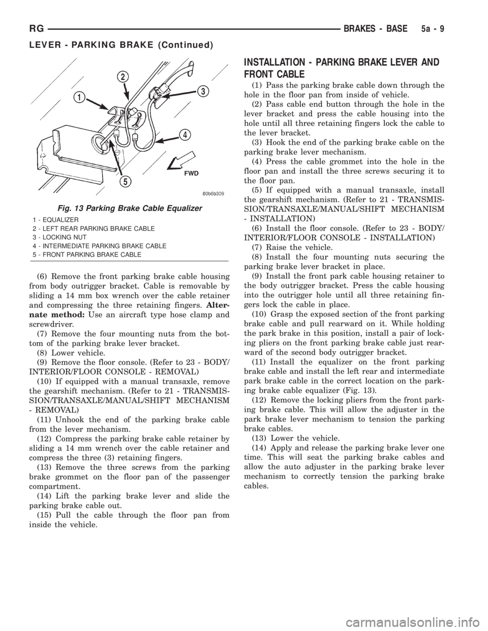
(11) Install the equalizer on the front parking
brake cable and install the left rear and intermediate
park brake cable in the correct location on the park-
ing brake cable equalizer (Fig. 13).
(12) Remove the locking pliers from the front park-
ing brake cable. This will allow the adjuster in the
park brake lever mechanism to tension the parking
brake cables.
(13) Lower the vehicle.
(14) Apply and release the parking brake lever one
time. This will seat the parking brake cables and
allow the auto adjuster in the parking brake lever
mechanism to correctly tension the parking brake
cables.
Fig. 13 Parking Brake Cable Equalizer
1 - EQUALIZER
2 - LEFT REAR PARKING BRAKE CABLE
3 - LOCKING NUT
4 - INTERMEDIATE PARKING BRAKE CABLE
5 - FRONT PARKING BRAKE CABLE
RGBRAKES - BASE5a-9
LEVER - PARKING BRAKE (Continued)
Page 1871 of 4284
BATTERY CABLES
DESCRIPTION
The battery cables are large gauge, stranded cop-
per wires sheathed within a heavy plastic or syn-
thetic rubber insulating jacket. The wire used in the
battery cables combines excellent flexibility and reli-
ability with high electrical current carrying capacity.
Refer toWiring Diagramsin the index of this ser-
vice manual for the location of the proper battery
cable wire gauge information.
A clamping type female battery terminal made of
soft lead is die cast onto one end of the battery cable
wire. A square headed pinch-bolt and hex nut are
installed at the open end of the female battery termi-
nal clamp. Large eyelet type terminals are crimped
onto the opposite end of the battery cable wire and
then solder-dipped. The battery positive cable wires
have a red insulating jacket to provide visual identi-
fication and feature a larger female battery terminal
clamp to allow connection to the larger battery posi-
tive terminal post. The battery negative cable wires
have a black insulating jacket and a smaller female
battery terminal clamp.
The battery cables cannot be repaired and, if dam-
aged or faulty they must be replaced. Both the bat-
tery positive and negative cables are available for
service replacement only as a unit with the battery
wire harness, which may include portions of the wir-
ing circuits for the generator and other components
on some models. Refer toWiring Diagramsin the
index of this service manual for the location of more
information on the various wiring circuits included in
the battery wire harness for the vehicle being ser-
viced.
OPERATION
The battery cables connect the battery terminal
posts to the vehicle electrical system. These cables
also provide a path back to the battery for electrical
current generated by the charging system for restor-
ing the voltage potential of the battery. The female
battery terminal clamps on the ends of the battery
cable wires provide a strong and reliable connection
of the battery cable to the battery terminal posts.
The terminal pinch bolts allow the female terminal
clamps to be tightened around the male terminal
posts on the top of the battery. The eyelet terminals
secured to the opposite ends of the battery cable
wires from the female battery terminal clamps pro-
vide secure and reliable connection of the battery
cables to the vehicle electrical system.The battery positive cable terminal clamp is die
cast onto the ends of two wires. One wire has an eye-
let terminal that connects the battery positive cable
to the B(+) terminal stud of the Intelligent Power
Module (IPM), and the other wire has an eyelet ter-
minal that connects the battery positive cable to the
B(+) terminal stud of the engine starter motor sole-
noid. The battery negative cable terminal clamp is
also die cast onto the ends of two wires. One wire
has an eyelet terminal that connects the battery neg-
ative cable to the vehicle powertrain through a stud
on the left side of the engine cylinder block. The
other wire has an eyelet terminal that connects the
battery negative cable to the vehicle body through a
ground screw on the left front fender inner shield,
near the battery.
DIAGNOSIS AND TESTING - BATTERY CABLE
A voltage drop test will determine if there is exces-
sive resistance in the battery cable terminal connec-
tions or the battery cable. If excessive resistance is
found in the battery cable connections, the connec-
tion point should be disassembled, cleaned of all cor-
rosion or foreign material, then reassembled.
Following reassembly, check the voltage drop for the
battery cable connection and the battery cable again
to confirm repair.
When performing the voltage drop test, it is impor-
tant to remember that the voltage drop is giving an
indication of the resistance between the two points at
which the voltmeter probes are attached.EXAM-
PLE:When testing the resistance of the battery pos-
itive cable, touch the voltmeter leads to the battery
positive cable terminal clamp and to the battery pos-
itive cable eyelet terminal at the starter solenoid
B(+) terminal stud. If you probe the battery positive
terminal post and the battery positive cable eyelet
terminal at the starter solenoid B(+) terminal stud,
you are reading the combined voltage drop in the
battery positive cable terminal clamp-to-terminal
post connection and the battery positive cable.
VOLTAGE DROP TEST
The following operation will require a voltmeter
accurate to 1/10 (0.10) volt. Before performing this
test, be certain that the following procedures are
accomplished:
²The battery is fully-charged and load tested.
Refer to Standard Procedures for the proper battery
charging and load test procedures.
²Fully engage the parking brake.
RSBATTERY SYSTEM8F-17
Page 1883 of 4284
CONDITION POSSIBLE CAUSE CORRECTION
3. STARTER ASSEMBLY
FAULTY.3. IF ALL OTHER STARTING SYSTEM COMPONENTS AND
CIRCUITS CHECK OK, REPLACE STARTER ASSEMBLY.
4. ENGINE SEIZED. 4. REFER TO THE ENGINE SECTION, FOR DIAGNOSTIC AND
SERVICE PROCEDURES.
5. LOOSE
CONNECTION AT
BATTERY, PDC,
STARTER, OR ENGINE
GROUND.5. INSPECT FOR LOOSE CONNECTIONS.
6. FAULTY TEETH ON
RING GEAR.6. ROTATE FLYWHEEL 360É, AND INSPECT TEETHAND RING
GEAR REPLACED IF DAMAGED.
STARTER
ENGAGES,
SPINS OUT
BEFORE
ENGINE
STARTS.1. BROKEN TEETH ON
STARTER RING GEAR.1. REMOVE STARTER. INSPECT RING GEAR AND REPLACE
IF NECESSARY.
2. STARTER ASSEMBLY
FAULTY.2. IF ALL OTHER STARTING SYSTEM COMPONENTS AND
CIRCUITS CHECK OK, REPLACE STARTER ASSEMBLY.
STARTER DOES
NOT
DISENGAGE.1. STARTER
IMPROPERLY
INSTALLED.1. INSTALL STARTER. TIGHTEN STARTER MOUNTING
HARDWARE TO CORRECT TORQUE SPECIFICATIONS.
2. STARTER RELAY
FAULTY.2. REFER TO RELAY TEST, IN THIS SECTION. REPLACE
RELAY, IF NECESSARY.
3. IGNITION SWITCH
FAULTY.3. REFER TO IGNITION SWITCH TEST, IN THE STEERING
SECTION.. REPLACE SWITCH, IF NECESSARY.
4. STARTER ASSEMBLY
FAULTY.4. IF ALL OTHER STARTING SYSTEM COMPONENTS AND
CIRCUITS CHECK OK, REPLACE STARTER ASSEMBLY.
5. FAULTY TEETH ON
RING GEAR.5. ROTATE FLYWHEEL 360É, AND INSPECT TEETH AND RING
GEAR REPLACED IF DAMAGED.
CONTROL CIRCUIT TEST
The starter control circuit has:
²Starter motor with integral solenoid
²Starter relay
²Transmission range sensor, or Park/Neutral
Position switch with automatic transmissions
²Ignition switch
²Battery
²All related wiring and connections
²Powertrain Control Module (PCM)
CAUTION: Before performing any starter tests, the
ignition and fuel systems must be disabled.
²To disable ignition and fuel systems, disconnect
the Automatic Shutdown Relay (ASD). The ASD relay
is located in the Power Distribution Center (PDC).
Refer to the PDC cover for the proper relay location.
STARTER SOLENOID
WARNING: CHECK TO ENSURE THAT THE TRANS-
MISSION IS IN THE PARK POSITION WITH THE
PARKING BRAKE APPLIED.
(1) Verify battery condition. Battery must be in
good condition with a full charge before performing
any starter tests. Refer to Battery Tests.
(2) Perform Starter Solenoid test BEFORE per-
forming the starter relay test.
(3) Perform a visual inspection of the starter/
starter solenoid for corrosion, loose connections or
faulty wiring.
(4) Locate and remove the starter relay from the
Power Distribution Center (PDC). Refer to the PDC
label for relay identification and location.
RSSTARTING8F-29
STARTING (Continued)
Page 1884 of 4284
(5) Connect a remote starter switch or a jumper
wire between the remote battery positive post and
terminal 87 of the starter relay connector.
(a) If engine cranks, starter/starter solenoid is
good. Go to the Starter Relay Test.
(b) If engine does not crank or solenoid chatters,
check wiring and connectors from starter relay to
starter solenoid for loose or corroded connections.
Particularly at starter terminals.
(c) Repeat test. If engine still fails to crank prop-
erly, trouble is within starter or starter mounted
solenoid, and replace starter.
STARTER RELAY
WARNING: CHECK TO ENSURE THAT THE TRANS-
MISSION IS IN THE PARK/NEUTRAL POSITION
WITH THE PARKING BRAKE APPLIED.
RELAY TEST
The starter relay is located in the Power Distribu-
tion Center (PDC) in the engine compartment. Refer
to the PDC label for relay identification and location.
Remove the starter relay from the PDC as
described in this group to perform the following tests:
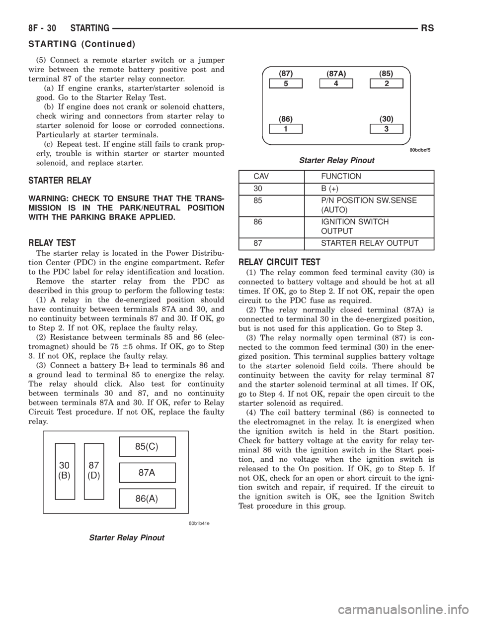
(1) A relay in the de-energized position should
have continuity between terminals 87A and 30, and
no continuity between terminals 87 and 30. If OK, go
to Step 2. If not OK, replace the faulty relay.
(2) Resistance between terminals 85 and 86 (elec-
tromagnet) should be 7565 ohms. If OK, go to Step
3. If not OK, replace the faulty relay.
(3) Connect a battery B+ lead to terminals 86 and
a ground lead to terminal 85 to energize the relay.
The relay should click. Also test for continuity
between terminals 30 and 87, and no continuity
between terminals 87A and 30. If OK, refer to Relay
Circuit Test procedure. If not OK, replace the faulty
relay.
CAV FUNCTION
30 B (+)
85 P/N POSITION SW.SENSE
(AUTO)
86 IGNITION SWITCH
OUTPUT
87 STARTER RELAY OUTPUT
RELAY CIRCUIT TEST
(1) The relay common feed terminal cavity (30) is
connected to battery voltage and should be hot at all
times. If OK, go to Step 2. If not OK, repair the open
circuit to the PDC fuse as required.
(2) The relay normally closed terminal (87A) is
connected to terminal 30 in the de-energized position,
but is not used for this application. Go to Step 3.
(3) The relay normally open terminal (87) is con-
nected to the common feed terminal (30) in the ener-
gized position. This terminal supplies battery voltage
to the starter solenoid field coils. There should be
continuity between the cavity for relay terminal 87
and the starter solenoid terminal at all times. If OK,
go to Step 4. If not OK, repair the open circuit to the
starter solenoid as required.
(4) The coil battery terminal (86) is connected to
the electromagnet in the relay. It is energized when
the ignition switch is held in the Start position.
Check for battery voltage at the cavity for relay ter-
minal 86 with the ignition switch in the Start posi-
tion, and no voltage when the ignition switch is
released to the On position. If OK, go to Step 5. If
not OK, check for an open or short circuit to the igni-
tion switch and repair, if required. If the circuit to
the ignition switch is OK, see the Ignition Switch
Test procedure in this group.
Starter Relay Pinout
Starter Relay Pinout
8F - 30 STARTINGRS
STARTING (Continued)
Page 1886 of 4284
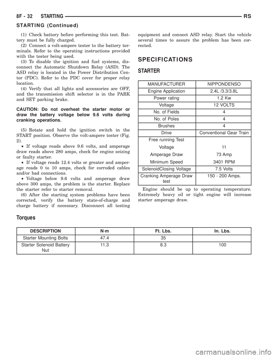
(1) Check battery before performing this test. Bat-
tery must be fully charged.
(2) Connect a volt-ampere tester to the battery ter-
minals. Refer to the operating instructions provided
with the tester being used.
(3) To disable the ignition and fuel systems, dis-
connect the Automatic Shutdown Relay (ASD). The
ASD relay is located in the Power Distribution Cen-
ter (PDC). Refer to the PDC cover for proper relay
location.
(4) Verify that all lights and accessories are OFF,
and the transmission shift selector is in the PARK
and SET parking brake.
CAUTION: Do not overheat the starter motor or
draw the battery voltage below 9.6 volts during
cranking operations.
(5) Rotate and hold the ignition switch in the
START position. Observe the volt-ampere tester (Fig.
2).
²If voltage reads above 9.6 volts, and amperage
draw reads above 280 amps, check for engine seizing
or faulty starter.
²If voltage reads 12.4 volts or greater and amper-
age reads 0 to 10 amps, check for corroded cables
and/or bad connections.
²Voltage below 9.6 volts and amperage draw
above 300 amps, the problem is the starter. Replace
the starter refer to starter removal.
(6) After the starting system problems have been
corrected, verify the battery state-of-charge and
charge battery if necessary. Disconnect all testingequipment and connect ASD relay. Start the vehicle
several times to assure the problem has been cor-
rected.
SPECIFICATIONS
STARTER
MANUFACTURER NIPPONDENSO
Engine Application 2.4L /3.3/3.8L
Power rating 1.2 Kw
Voltage 12 VOLTS
No. of Fields 4
No. of Poles 4
Brushes 4
Drive Conventional Gear Train
Free running Test
Voltage 11
Amperage Draw 73 Amp
Minimum Speed 3401 RPM
SolenoidClosing Voltage 7.5 Volts
Cranking Amperage Draw
test150 - 200 Amps.
Engine should be up to operating temperature.
Extremely heavy oil or tight engine will increase
starter amperage draw.
Torques
DESCRIPTION N´m Ft. Lbs. In. Lbs.
Starter Mounting Bolts 47.4 35
Starter Solenoid Battery
Nut11.3 8.3 100
8F - 32 STARTINGRS
STARTING (Continued)
Page 1938 of 4284
(11) Install the lower steering column cover. Refer
to Body, Instrument Panel, Lower Steering Column
Cover, Installation.
(12) Connect the battery negative cable.
CLUSTER LENS
REMOVAL
(1) Remove the instrument cluster. Refer to Elec-
trical, Instrument Cluster, Removal.
(2) Remove the screws holding the lens to the
instrument cluster.
(3) Press down on the snap features of the lens
and remove the lens from the cluster.
INSTALLATION
(1) Insert the lens snap features into the cluster.
(2) Install the screws holding the lens to the
instrument cluster.
(3) Install the instrument cluster. Refer to Electri-
cal, Instrument Cluster, Installation.
MECHANICAL TRANSMISSION
RANGE INDICATOR
REMOVAL
(1) Remove the instrument cluster and disconnect
the range indicator cable at both attaching points.
Refer to Electrical, Instrument Cluster, Removal.
(2) From the backside of the cluster, remove two
screws holding the mechanical transmission rangeindicator and then remove it fromt instrument clus-
ter.
INSTALLATION
(1) Insert the mechanical transmission range indi-
cator into the backside of the instrument cluster and
install the two screws.
(2) Install the instrument cluster. Refer to Electri-
cal, Instrument Cluster, Installation.
RED BRAKE WARNING
INDICATOR
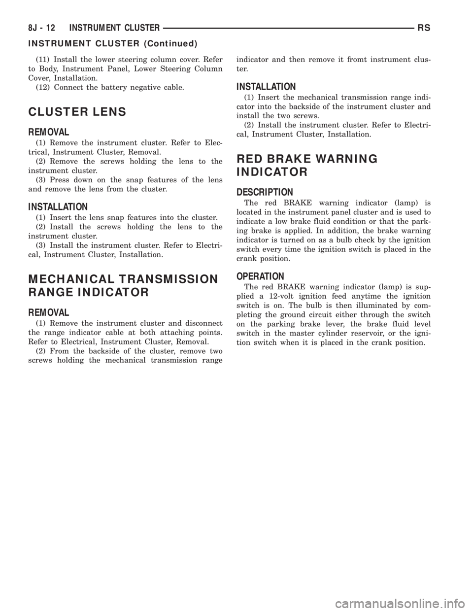
DESCRIPTION
The red BRAKE warning indicator (lamp) is
located in the instrument panel cluster and is used to
indicate a low brake fluid condition or that the park-
ing brake is applied. In addition, the brake warning
indicator is turned on as a bulb check by the ignition
switch every time the ignition switch is placed in the
crank position.
OPERATION
The red BRAKE warning indicator (lamp) is sup-
plied a 12-volt ignition feed anytime the ignition
switch is on. The bulb is then illuminated by com-
pleting the ground circuit either through the switch
on the parking brake lever, the brake fluid level
switch in the master cylinder reservoir, or the igni-
tion switch when it is placed in the crank position.
8J - 12 INSTRUMENT CLUSTERRS
INSTRUMENT CLUSTER (Continued)
Page 1946 of 4284
CONDITION POSSIBLE CAUSES CORRECTION
3. Faulty fog lamp switch (part of
headlamp switch).3. Replace headlamp switch.
4. Loose or corroded terminals or
splices in circuit.4. Inspect and repair all connectors and
splices. Refer to Electrical, Wiring
Information.
5. Is relay engaging properly? 5. Verify function of fog lamp relay in IPM.
6. J1850 Bus Communication. 6. Verify J1850 message (fog lamp info)
transmitted from BCM and received by
FCM.
FOG LAMPS DO NOT
ILLUMINATE1. Blown fuse for fog lamp. 1. Replace fuse. Refer to Electrical, Wiring
Information.
2. No Z349/Z248 ground at fog
lamps.2. Repair circuit ground. Refer to Electrical,
Wiring Information.
3. Faulty fog lamp switch (part of
headlamp switch).3. Replace headlamp switch.
4. Broken connector terminal or wire
splice in fog lamp circuit.4. Repair connector terminal or wire splice.
5. Faulty or burned out bulb. 5. Replace bulb.
6. Is relay engaging? 6. Verify function of fog lamp relay in IPM.
7. J1850 Bus Communication. 7. Verify J1850 message (fog lamp info)
transmitted from BCM and received by
FCM.
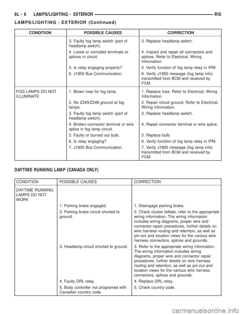
DAYTIME RUNNING LAMP (CANADA ONLY)
CONDITION POSSIBLE CAUSES CORRECTION
DAYTIME RUNNING
LAMPS DO NOT
WORK
1. Parking brake engaged. 1. Disengage parking brake.
2. Parking brake circuit shorted to
ground.2. Check cluster telltale, refer to the appropriate
wiring information. The wiring information
includes wiring diagrams, proper wire and
connector repair procedures, further details on
wire harness routing and retention, as well as
pin-out and location views for the various wire
harness connectors, splices and grounds.
3. Headlamp circuit shorted to ground. 3. Refer to the appropriate wiring information.
The wiring information includes wiring
diagrams, proper wire and connector repair
procedures, further details on wire harness
routing and retention, as well as pin-out and
location views for the various wire harness
connectors, splices and grounds.
4. Faulty DRL relay. 4. Replace DRL relay.
5. Body controller not programed with
Canadian country code.5. Check country code.
8L - 6 LAMPS/LIGHTING - EXTERIORRS
LAMPS/LIGHTING - EXTERIOR (Continued)
Page 2027 of 4284
The driver side automatic dimming mirror is stan-
dard with the automatic dimming inside mirror. The
signal to control the dimming of that mirror is gen-
erated by the automatic day/night inside rear view
mirror circuitry. That signal is then delivered to the
driver side outside rear view mirror on a hard wired
circuit.
The automatic day/night mirror cannot be
repaired. If faulty or damaged, the entire inside rear
view mirror assembly must be replaced.
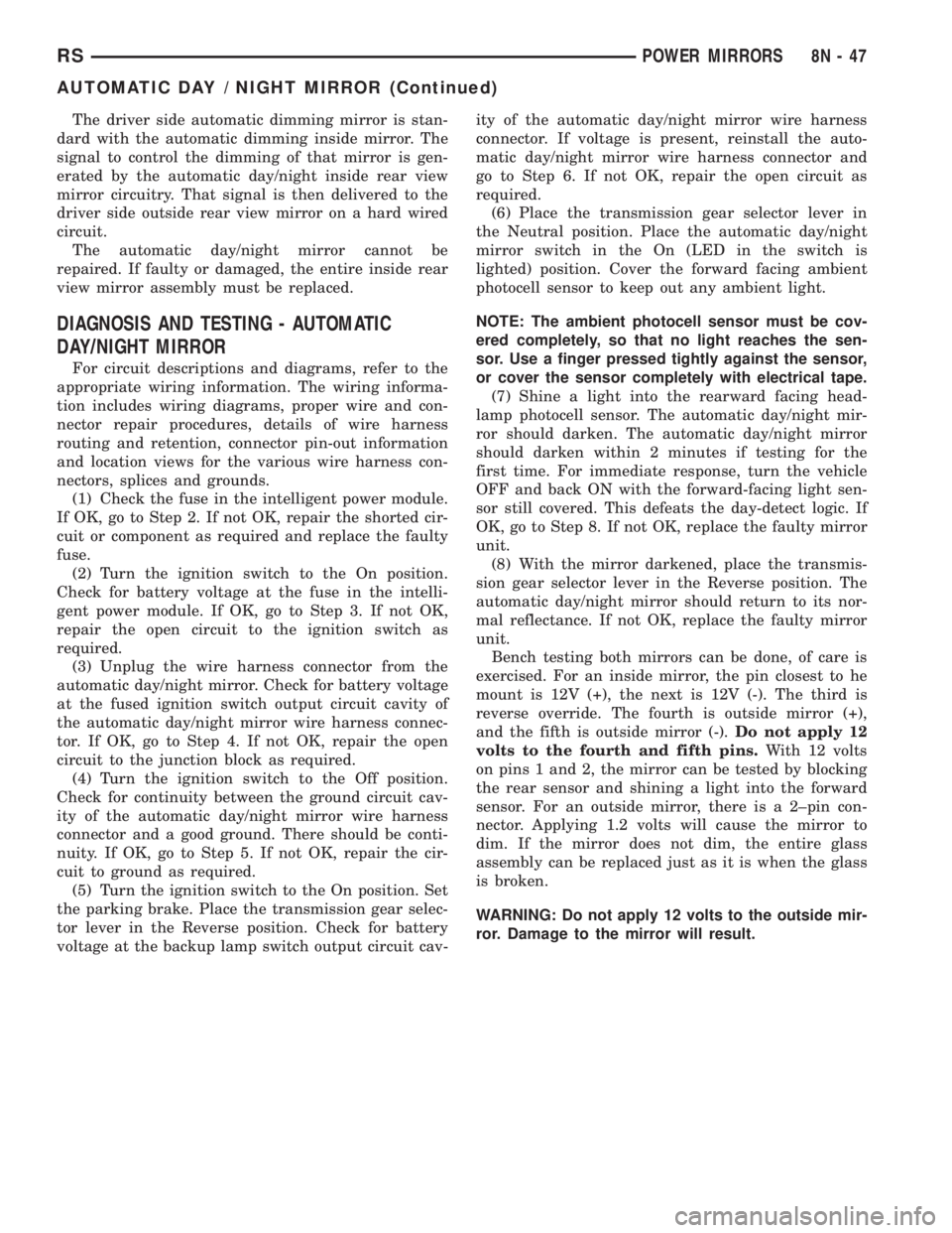
DIAGNOSIS AND TESTING - AUTOMATIC
DAY/NIGHT MIRROR
For circuit descriptions and diagrams, refer to the
appropriate wiring information. The wiring informa-
tion includes wiring diagrams, proper wire and con-
nector repair procedures, details of wire harness
routing and retention, connector pin-out information
and location views for the various wire harness con-
nectors, splices and grounds.
(1) Check the fuse in the intelligent power module.
If OK, go to Step 2. If not OK, repair the shorted cir-
cuit or component as required and replace the faulty
fuse.
(2) Turn the ignition switch to the On position.
Check for battery voltage at the fuse in the intelli-
gent power module. If OK, go to Step 3. If not OK,
repair the open circuit to the ignition switch as
required.
(3) Unplug the wire harness connector from the
automatic day/night mirror. Check for battery voltage
at the fused ignition switch output circuit cavity of
the automatic day/night mirror wire harness connec-
tor. If OK, go to Step 4. If not OK, repair the open
circuit to the junction block as required.
(4) Turn the ignition switch to the Off position.
Check for continuity between the ground circuit cav-
ity of the automatic day/night mirror wire harness
connector and a good ground. There should be conti-
nuity. If OK, go to Step 5. If not OK, repair the cir-
cuit to ground as required.
(5) Turn the ignition switch to the On position. Set
the parking brake. Place the transmission gear selec-
tor lever in the Reverse position. Check for battery
voltage at the backup lamp switch output circuit cav-ity of the automatic day/night mirror wire harness
connector. If voltage is present, reinstall the auto-
matic day/night mirror wire harness connector and
go to Step 6. If not OK, repair the open circuit as
required.
(6) Place the transmission gear selector lever in
the Neutral position. Place the automatic day/night
mirror switch in the On (LED in the switch is
lighted) position. Cover the forward facing ambient
photocell sensor to keep out any ambient light.
NOTE: The ambient photocell sensor must be cov-
ered completely, so that no light reaches the sen-
sor. Use a finger pressed tightly against the sensor,
or cover the sensor completely with electrical tape.
(7) Shine a light into the rearward facing head-
lamp photocell sensor. The automatic day/night mir-
ror should darken. The automatic day/night mirror
should darken within 2 minutes if testing for the
first time. For immediate response, turn the vehicle
OFF and back ON with the forward-facing light sen-
sor still covered. This defeats the day-detect logic. If
OK, go to Step 8. If not OK, replace the faulty mirror
unit.
(8) With the mirror darkened, place the transmis-
sion gear selector lever in the Reverse position. The
automatic day/night mirror should return to its nor-
mal reflectance. If not OK, replace the faulty mirror
unit.
Bench testing both mirrors can be done, of care is
exercised. For an inside mirror, the pin closest to he
mount is 12V (+), the next is 12V (-). The third is
reverse override. The fourth is outside mirror (+),
and the fifth is outside mirror (-).Do not apply 12
volts to the fourth and fifth pins.With 12 volts
on pins 1 and 2, the mirror can be tested by blocking
the rear sensor and shining a light into the forward
sensor. For an outside mirror, there is a 2±pin con-
nector. Applying 1.2 volts will cause the mirror to
dim. If the mirror does not dim, the entire glass
assembly can be replaced just as it is when the glass
is broken.
WARNING: Do not apply 12 volts to the outside mir-
ror. Damage to the mirror will result.
RSPOWER MIRRORS8N-47
AUTOMATIC DAY / NIGHT MIRROR (Continued)