2001 CHRYSLER VOYAGER parking brake
[x] Cancel search: parking brakePage 3212 of 4284
(5) Pour four quarts of Moparž ATF+4 (Automatic
Transmission Fluid) Type 9602 through the dipstick
opening.
(6) Start engine and allow to idle for at least one
minute. Then, with parking and service brakes
applied, move selector lever momentarily to each
position, ending in the park or neutral position.
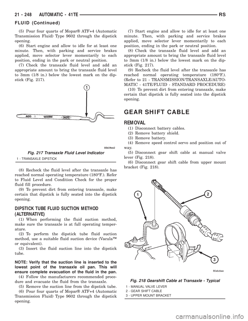
(7) Check the transaxle fluid level and add an
appropriate amount to bring the transaxle fluid level
to 3mm (1/8 in.) below the lowest mark on the dip-
stick (Fig. 217).
(8) Recheck the fluid level after the transaxle has
reached normal operating temperature (180ÉF.). Refer
to Fluid Level and Condition Check for the proper
fluid fill procedure.
(9) To prevent dirt from entering transaxle, make
certain that dipstick is fully seated into the dipstick
opening.
DIPSTICK TUBE FLUID SUCTION METHOD
(ALTERNATIVE)
(1) When performing the fluid suction method,
make sure the transaxle is at full operating temper-
ature.
(2) To perform the dipstick tube fluid suction
method, use a suitable fluid suction device (VaculaŸ
or equivalent).
(3) Insert the fluid suction line into the dipstick
tube.
NOTE: Verify that the suction line is inserted to the
lowest point of the transaxle oil pan. This will
ensure complete evacuation of the fluid in the pan.
(4) Follow the manufacturers recommended proce-
dure and evacuate the fluid from the transaxle.
(5) Remove the suction line from the dipstick tube.
(6) Pour four quarts of Moparž ATF+4 (Automatic
Transmission Fluid) Type 9602 through the dipstick
opening.(7) Start engine and allow to idle for at least one
minute. Then, with parking and service brakes
applied, move selector lever momentarily to each
position, ending in the park or neutral position.
(8) Check the transaxle fluid level and add an
appropriate amount to bring the transaxle fluid level
to 3mm (1/8 in.) below the lowest mark on the dip-
stick (Fig. 217).
(9) Recheck the fluid level after the transaxle has
reached normal operating temperature (180ÉF.).
(Refer to 21 - TRANSMISSION/TRANSAXLE/AUTO-
MATIC - 41TE/FLUID - STANDARD PROCEDURE)
(10) To prevent dirt from entering transaxle, make
certain that dipstick is fully seated into the dipstick
opening.
GEAR SHIFT CABLE
REMOVAL
(1) Disconnect battery cables.
(2) Remove battery shield.
(3) Remove battery.
(4) Remove speed control servo and position out of
way.
(5) Disconnect gear shift cable at manual valve
lever (Fig. 218).
(6) Disconnect gear shift cable from upper mount
bracket (Fig. 218).
Fig. 217 Transaxle Fluid Level Indicator
1 - TRANSAXLE DIPSTICK
Fig. 218 Gearshift Cable at Transaxle - Typical
1 - MANUAL VALVE LEVER
2 - GEAR SHIFT CABLE
3 - UPPER MOUNT BRACKET
21 - 248 AUTOMATIC - 41TERS
FLUID (Continued)
Page 3215 of 4284
GEARSHIFT CABLE ADJUSTMENT
VERIFICATION
(1) Place gearshift lever in gated park (P).
(2) Attempt to move vehicle by rocking back and
forth on level ground. If vehicle does not move,
attempt to start engine. If engine starts, the park
position is correct.
(3) Set parking brake.
(4) Turn key to on/run and depress brake pedal.
Place gearshift lever in neutral (N).
(5) Attempt to start engine. If engine starts in
both neutral (N) or park (P), gearshift cable is
adjusted properly. No adjustment is required.
(6) If engine does not start in either park (P) or
neutral (N), perform adjustment procedure.
ADJUSTMENT
(1) Park the vehicle on level ground and set the
parking brake.
(2) Place the gearshift lever in gated park (P) and
remove ignition key.
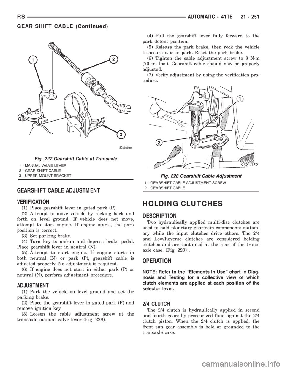
(3) Loosen the cable adjustment screw at the
transaxle manual valve lever (Fig. 228).(4) Pull the gearshift lever fully forward to the
park detent position.
(5) Release the park brake, then rock the vehicle
to assure it is in park. Reset the park brake.
(6) Tighten the cable adjustment screw to 8 N´m
(70 in. lbs.). Gearshift cable should now be properly
adjusted.
(7) Verify adjustment by using the verification pro-
cedure.
HOLDING CLUTCHES
DESCRIPTION
Two hydraulically applied multi-disc clutches are
used to hold planetary geartrain components station-
ary while the input clutches drive others. The 2/4
and Low/Reverse clutches are considered holding
clutches and are contained at the rear of the trans-
axle case. (Fig. 229) .
OPERATION
NOTE: Refer to the ªElements In Useº chart in Diag-
nosis and Testing for a collective view of which
clutch elements are applied at each position of the
selector lever.
2/4 CLUTCH
The 2/4 clutch is hydraulically applied in second
and fourth gears by pressurized fluid against the 2/4
clutch piston. When the 2/4 clutch is applied, the
front sun gear assembly is held or grounded to the
transaxle case.
Fig. 227 Gearshift Cable at Transaxle
1 - MANUAL VALVE LEVER
2 - GEAR SHIFT CABLE
3 - UPPER MOUNT BRACKET
Fig. 228 Gearshift Cable Adjustment
1 - GEARSHIFT CABLE ADJUSTMENT SCREW
2 - GEARSHIFT CABLE
RSAUTOMATIC - 41TE21 - 251
GEAR SHIFT CABLE (Continued)
Page 3390 of 4284
LUBRICANT USAGE
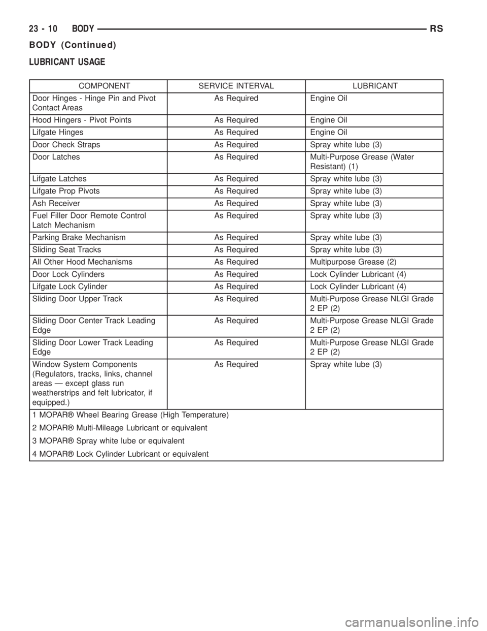
COMPONENT SERVICE INTERVAL LUBRICANT
Door Hinges - Hinge Pin and Pivot
Contact AreasAs Required Engine Oil
Hood Hingers - Pivot Points As Required Engine Oil
Lifgate Hinges As Required Engine Oil
Door Check Straps As Required Spray white lube (3)
Door Latches As Required Multi-Purpose Grease (Water
Resistant) (1)
Lifgate Latches As Required Spray white lube (3)
Lifgate Prop Pivots As Required Spray white lube (3)
Ash Receiver As Required Spray white lube (3)
Fuel Filler Door Remote Control
Latch MechanismAs Required Spray white lube (3)
Parking Brake Mechanism As Required Spray white lube (3)
Sliding Seat Tracks As Required Spray white lube (3)
All Other Hood Mechanisms As Required Multipurpose Grease (2)
Door Lock Cylinders As Required Lock Cylinder Lubricant (4)
Lifgate Lock Cylinder As Required Lock Cylinder Lubricant (4)
Sliding Door Upper Track As Required Multi-Purpose Grease NLGI Grade
2 EP (2)
Sliding Door Center Track Leading
EdgeAs Required Multi-Purpose Grease NLGI Grade
2 EP (2)
Sliding Door Lower Track Leading
EdgeAs Required Multi-Purpose Grease NLGI Grade
2 EP (2)
Window System Components
(Regulators, tracks, links, channel
areas Ð except glass run
weatherstrips and felt lubricator, if
equipped.)As Required Spray white lube (3)
1 MOPARž Wheel Bearing Grease (High Temperature)
2 MOPARž Multi-Mileage Lubricant or equivalent
3 MOPARž Spray white lube or equivalent
4 MOPARž Lock Cylinder Lubricant or equivalent
23 - 10 BODYRS
BODY (Continued)
Page 3767 of 4284
PCV VALVE
DESCRIPTION
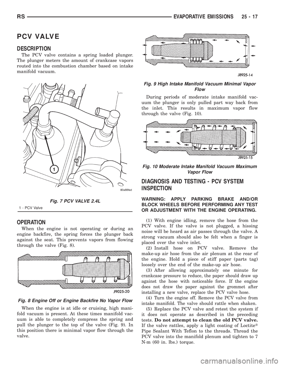
The PCV valve contains a spring loaded plunger.
The plunger meters the amount of crankcase vapors
routed into the combustion chamber based on intake
manifold vacuum.
OPERATION
When the engine is not operating or during an
engine backfire, the spring forces the plunger back
against the seat. This prevents vapors from flowing
through the valve (Fig. 8).
When the engine is at idle or cruising, high mani-
fold vacuum is present. At these times manifold vac-
uum is able to completely compress the spring and
pull the plunger to the top of the valve (Fig. 9). In
this position there is minimal vapor flow through the
valve.During periods of moderate intake manifold vac-
uum the plunger is only pulled part way back from
the inlet. This results in maximum vapor flow
through the valve (Fig. 10).
DIAGNOSIS AND TESTING - PCV SYSTEM
INSPECTION
WARNING: APPLY PARKING BRAKE AND/OR
BLOCK WHEELS BEFORE PERFORMING ANY TEST
OR ADJUSTMENT WITH THE ENGINE OPERATING.
(1) With engine idling, remove the hose from the
PCV valve. If the valve is not plugged, a hissing
noise will be heard as air passes through the valve. A
strong vacuum should also be felt when a finger is
placed over the valve inlet.
(2) Install hose on PCV valve. Remove the
make-up air hose from the air plenum at the rear of
the engine. Hold a piece of stiff paper (parts tag)
loosely over the end of the make-up air hose.
(3)
After allowing approximately one minute for
crankcase pressure to reduce, the paper should draw up
against the hose with noticeable force. If the engine
does not draw the paper against the grommet after
installing a new valve, replace the PCV valve hose.
(4)Turn the engine off. Remove the PCV valve from
intake manifold. The valve should rattle when shaken.
(5) Replace the PCV valve and retest the system if
it does not operate as described in the preceding
tests.Do not attempt to clean the old PCV valve.
If the valve rattles, apply a light coating of Loctitet
Pipe Sealant With Teflon to the threads. Thread the
PCV valve into the manifold plenum and tighten to 7
N´m (60 in. lbs.) torque.
Fig. 7 PCV VALVE 2.4L
1 - PCV Valve
Fig. 8 Engine Off or Engine Backfire No Vapor Flow
Fig. 9 High Intake Manifold Vacuum Minimal Vapor
Flow
Fig. 10 Moderate Intake Manifold Vacuum Maximum
Vapor Flow
RSEVAPORATIVE EMISSIONS25-17
Page 3804 of 4284
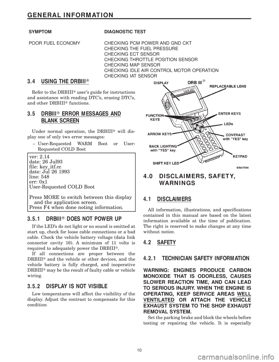
SYMPTOM DIAGNOSTIC TEST
POOR FUEL ECONOMY CHECKING PCM POWER AND GND CKT
CHECKING THE FUEL PRESSURE
CHECKING ECT SENSOR
CHECKING THROTTLE POSITION SENSOR
CHECKING MAP SENSOR
CHECKING IDLE AIR CONTROL MOTOR OPERATION
CHECKING IAT SENSOR
3.4 USING THE DRBIIIT
Refer to the DRBIIItuser 's guide for instructions
and assistance with reading DTC's, erasing DTC's,
and other DRBIIItfunctions.
3.5 DRBIIITERROR MESSAGES AND
BLANK SCREEN
Under normal operation, the DRBIIItwill dis-
play one of only two error messages:
± User-Requested WARM Boot or User-
Requested COLD Boot
ver: 2.14
date: 26 Jul93
file: key_itf.cc
date: Jul 26 1993
line: 548
err: 0x1
User-Requested COLD Boot
Press MORE to switch between this display
and the application screen.
Press F4 when done noting information.
3.5.1 DRBIIITDOES NOT POWER UP
If the LED's do not light or no sound is emitted at
start up, check for loose cable connections or a bad
cable. Check the vehicle battery voltage (data link
connector cavity 16). A minimum of 11 volts is
required to adequately power the DRBIIIt.
If all connections are proper between the
DRBIIItand the vehicle or other devices, and the
vehicle battery is fully charged, and inoperative
DRBIIItmay be the result of faulty cable or vehicle
wiring.
3.5.2 DISPLAY IS NOT VISIBLE
Low temperatures will affect the visibility of the
display. Adjust the contrast to compensate for this
condition
4.0 DISCLAIMERS, SAFETY,
WARNINGS
4.1 DISCLAIMERS
All information, illustrations, and specifications
contained in this manual are based on the latest
information available at the time of publication.
The right is reserved to make changes at any time
without notice.
4.2 SAFETY
4.2.1 TECHNICIAN SAFETY INFORMATION
WARNING: ENGINES PRODUCE CARBON
MONOXIDE THAT IS ODORLESS, CAUSES
SLOWER REACTION TIME, AND CAN LEAD
TO SERIOUS INJURY. WHEN THE ENGINE IS
OPERATING, KEEP SERVICE AREAS WELL
VENTILATED OR ATTACH THE VEHICLE
EXHAUST SYSTEM TO THE SHOP EXHAUST
REMOVAL SYSTEM.
Set the parking brake and block the wheels before
testing or repairing the vehicle. It is especially
10
GENERAL INFORMATION
Page 3805 of 4284
important to block the wheels on front-wheel drive
vehicles; the parking brake does not hold the drive
wheels.
When servicing a vehicle, always wear eye pro-
tection, and remove any metal jewelry such as
watchbands or bracelets that might make an inad-
vertent electrical contact.
When diagnosing a powertrain system problem,
it is important to follow approved procedures where
applicable. These procedures can be found in ser-
vice manual procedures. Following these proce-
dures is very important to the safety of individuals
performing diagnostic tests.
4.2.2 VEHICLE PREPARATION FOR
TESTING
Make sure the vehicle being tested has a fully
charged battery. If it does not, false diagnostic codes
or error messages may occur.
4.2.3 SERVICING SUB ASSEMBLIES
Some components of the powertrain system are
intended to be serviced in assembly only. Attempt-
ing to remove or repair certain system sub-
components may result in personal injury and/or
improper system operation. Only those components
with approved repair and installation procedures in
the service manual should be serviced.
4.2.4 DRBIIITSAFETY INFORMATION
WARNING: EXCEEDING THE LIMITS OF THE
DRB MULTIMETER IS DANGEROUS. IT CAN
EXPOSE YOU TO SERIOUS INJURY.
CAREFULLY READ AND UNDERSTAND THE
CAUTIONS AND THE SPECIFICATION
LIMITS.
Follow the vehicle manufacturer 's service specifi-
cations at all times.
²Do not use the DRB if it has been damaged.
²Do not use the test leads if the insulation is
damaged or if metal is exposed.
²To avoid electrical shock, do not touch the test
leads, tips, or the circuit being tested.
²Choose the proper range and function for the
measurement. Do not try voltage or current mea-
surements that may exceed the rated capacity.
²Do not exceed the limits shown in the table below:
FUNCTION INPUT LIMIT
Volts 0 - 500 peak volts AC
0 - 500 volts DC
Ohms (resistance)* 0 - 1.12 megohms
FUNCTION INPUT LIMIT
Frequency Measured
Frequency Generated0-10kHz
Temperature -58 - 1100ÉF
-50 - 600ÉC
* Ohms cannot be measured if voltage is present.
Ohms can be measured only in a non-powered
circuit.
²Voltage between any terminal and ground must
not exceed 500v DC or 500v peak AC.
²Use caution when measuring voltage above 25v
DC or 25v AC.
²The circuit being tested must be protected by a
10A fuse or circuit breaker.
²Use the low current shunt to measure circuits up
to 10A. Use the high current clamp to measure
circuits exceeding 10A.
²When testing for the presence of voltage or cur-
rent, make sure the meter is functioning cor-
rectly. Take a reading of a known voltage or
current before accepting a zero reading.
²When measuring current, connect the meter in
series with the load.
²Disconnect the live test lead before disconnecting
the common test lead.
²When using the meter function, keep the DRBIIIt
away from spark plug or coil wires to avoid mea-
suring error from outside interference.
4.3 WARNINGS AND CAUTIONS
4.3.1 ROAD TEST WARNINGS
Some complaints will require a test drive as part
of the repair verification procedure. The purpose of
the test drive is to try to duplicate the diagnostic
code or symptom condition.
CAUTION: BEFORE ROAD TESTING A
VEHICLE, BE SURE THAT ALL
COMPONENTS ARE REASSEMBLED.
DURING THE TEST DRIVE, DO NOT TRY TO
READ THE DRBIIITSCREEN WHILE IN
MOTION. DO NOT HANG THE DRBIIITFROM
THE REAR VIEW MIRROR OR OPERATE IT
YOURSELF. HAVE AN ASSISTANT
AVAILABLE TO OPERATE THE DRBIIIT.
4.3.2 VEHICLE DAMAGE CAUTIONS
Before disconnecting any control module, make
sure the ignition is off. Failure to do so could
damage the module.
11
GENERAL INFORMATION
Page 4053 of 4284

TEST ACTION APPLICABILITY
4 Turn ignition off.
Remove the Starter Relay from PDC.
WARNING: The Parking Brake must be on and the Transmission must be in
park for a vehicle equipped with an automatic transmission.
Warning: The engine may be cranked in the next step. Keep away from
moving engine parts.
Briefly connect a jumper wire between Starter Relay B+ circuit and the Starter Relay
Output Circuits.
Did the Starter Motor crank the engine?All
Ye s®Go To 5
No®Go To 8
5 Turn the ignition off.
Remove the Starter Relay from the PDC.
Turn the ignition on.
Using a 12-volt test light, probe the Ignition Switch Output circuit in the Starter
Relay connector.
While observing 12-volt test light, hold ignition key in the start position.
Does the test light illuminate brightly?All
Ye s®Go To 6
No®Repair the Ignition Switch Output circuit for an open or high
resistance.
Perform POWERTRAIN VERIFICATION TEST VER-1.
6 Turn the ignition off.
Remove the Starter Relay from the PDC.
Disconnect the PCM harness connector.
Measure the Starter Relay Control circuit between the Relay terminal and the PCM
harness connector.
Is the resistance below 5.0 ohms?All
Ye s®Go To 7
No®Repair the Starter Relay Control circuit for an open.
Perform POWERTRAIN VERIFICATION TEST VER-1.
7 Turn the ignition off.
Install a substitute a Relay in the of the Starter Motor Relay.
Attempt to start the vehicle.
Does the engine crank over?All
Ye s®Replace the Starter Motor Relay.
Perform POWERTRAIN VERIFICATION TEST VER-1.
No®Replace and program the Powertrain Control Module in accor-
dance with the Service Information.
Perform POWERTRAIN VERIFICATION TEST VER-1.
259
STARTING
*NO CRANK CONDITION ÐContinued