2001 CHRYSLER VOYAGER stop start
[x] Cancel search: stop startPage 4057 of 4284
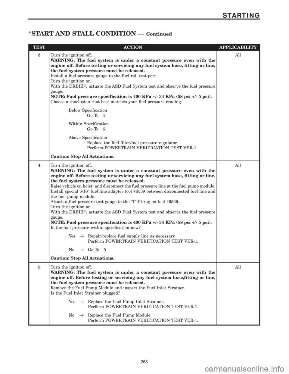
TEST ACTION APPLICABILITY
3 Turn the ignition off.
WARNING: The fuel system is under a constant pressure even with the
engine off. Before testing or servicing any fuel system hose, fitting or line,
the fuel system pressure must be released.
Install a fuel pressure gauge to the fuel rail test port.
Turn the ignition on.
With the DRBIIIt, actuate the ASD Fuel System test and observe the fuel pressure
gauge.
NOTE: Fuel pressure specification is 400 KPa +/- 34 KPa (58 psi +/- 5 psi).
Choose a conclusion that best matches your fuel pressure reading.All
Below Specification
Go To 4
Within Specification
Go To 6
Above Specification
Replace the fuel filter/fuel pressure regulator.
Perform POWERTRAIN VERIFICATION TEST VER-1.
Caution: Stop All Actuations.
4 Turn the ignition off.
WARNING: The fuel system is under a constant pressure even with the
engine off. Before testing or servicing any fuel system hose, fitting or line,
the fuel system pressure must be released.
Raise vehicle on hoist, and disconnect the fuel pressure line at the fuel pump module.
Install special 5/169fuel line adapter tool #6539 between disconnected fuel line and
the fuel pump module.
Attach a fuel pressure test gauge to the9T9fitting on tool #6539.
Turn the ignition on.
With the DRBIIIt, actuate the ASD Fuel System test and observe the fuel pressure
gauge.
NOTE: Fuel pressure specification is 400 KPa +/- 34 KPa (58 psi +/- 5 psi).
Is the fuel pressure within specification now?All
Ye s®Repair/replace fuel supply line as necessary.
Perform POWERTRAIN VERIFICATION TEST VER-1.
No®Go To 5
Caution: Stop All Actuations.
5 Turn the ignition off.
WARNING: The fuel system is under a constant pressure even with the
engine off. Before testing or servicing any fuel system hose,fitting or line,
the fuel system pressure must be released.
Remove the Fuel Pump Module and inspect the Fuel Inlet Strainer.
Is the Fuel Inlet Strainer plugged?All
Ye s®Replace the Fuel Pump Inlet Strainer.
Perform POWERTRAIN VERIFICATION TEST VER-1.
No®Replace the Fuel Pump Module.
Perform POWERTRAIN VERIFICATION TEST VER-1.
263
STARTING
*START AND STALL CONDITION ÐContinued
Page 4058 of 4284
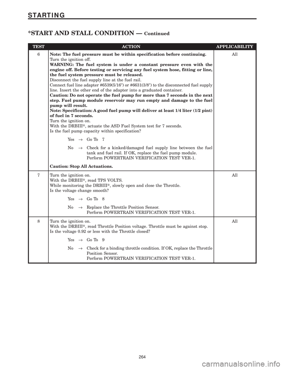
TEST ACTION APPLICABILITY
6Note: The fuel pressure must be within specification before continuing.
Turn the ignition off.
WARNING: The fuel system is under a constant pressure even with the
engine off. Before testing or servicing any fuel system hose, fitting or line,
the fuel system pressure must be released.
Disconnect the fuel supply line at the fuel rail.
Connect fuel line adapter #6539(5/169) or #6631(3/89) to the disconnected fuel supply
line. Insert the other end of the adapter into a graduated container.
Caution: Do not operate the fuel pump for more than 7 seconds in the next
step. Fuel pump module reservoir may run empty and damage to the fuel
pump will result.
Note: Specification: A good fuel pump will deliver at least 1/4 liter (1/2 pint)
of fuel in 7 seconds.
Turn the ignition on.
With the DRBIIIt, actuate the ASD Fuel System test for 7 seconds.
Is the fuel pump capacity within specification?All
Ye s®Go To 7
No®Check for a kinked/damaged fuel supply line between the fuel
tank and fuel rail. If OK, replace the fuel pump module.
Perform POWERTRAIN VERIFICATION TEST VER-1.
Caution: Stop All Actuations.
7 Turn the ignition on.
With the DRBIIIt, read TPS VOLTS.
While monitoring the DRBIIIt, slowly open and close the Throttle.
Is the voltage change smooth?All
Ye s®Go To 8
No®Replace the Throttle Position Sensor.
Perform POWERTRAIN VERIFICATION TEST VER-1.
8 Turn the ignition on.
With the DRBIIIt, read Throttle Position voltage. Throttle must be against stop.
Is the voltage 0.92 or less with the Throttle closed?All
Ye s®Go To 9
No®Check for a binding throttle condition. If OK, replace the Throttle
Position Sensor.
Perform POWERTRAIN VERIFICATION TEST VER-1.
264
STARTING
*START AND STALL CONDITION ÐContinued
Page 4106 of 4284
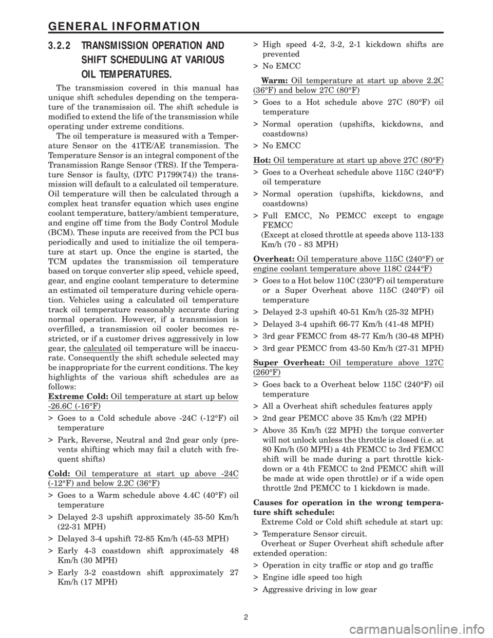
3.2.2 TRANSMISSION OPERATION AND
SHIFT SCHEDULING AT VARIOUS
OIL TEMPERATURES.
The transmission covered in this manual has
unique shift schedules depending on the tempera-
ture of the transmission oil. The shift schedule is
modified to extend the life of the transmission while
operating under extreme conditions.
The oil temperature is measured with a Temper-
ature Sensor on the 41TE/AE transmission. The
Temperature Sensor is an integral component of the
Transmission Range Sensor (TRS). If the Tempera-
ture Sensor is faulty, (DTC P1799(74)) the trans-
mission will default to a calculated oil temperature.
Oil temperature will then be calculated through a
complex heat transfer equation which uses engine
coolant temperature, battery/ambient temperature,
and engine off time from the Body Control Module
(BCM). These inputs are received from the PCI bus
periodically and used to initialize the oil tempera-
ture at start up. Once the engine is started, the
TCM updates the transmission oil temperature
based on torque converter slip speed, vehicle speed,
gear, and engine coolant temperature to determine
an estimated oil temperature during vehicle opera-
tion. Vehicles using a calculated oil temperature
track oil temperature reasonably accurate during
normal operation. However, if a transmission is
overfilled, a transmission oil cooler becomes re-
stricted, or if a customer drives aggressively in low
gear, the calculated oil temperature will be inaccu-
rate. Consequently the shift schedule selected may
be inappropriate for the current conditions. The key
highlights of the various shift schedules are as
follows:
Extreme Cold:Oil temperature at start up below
-26.6C (-16ÉF)
> Goes to a Cold schedule above -24C (-12ÉF) oil
temperature
> Park, Reverse, Neutral and 2nd gear only (pre-
vents shifting which may fail a clutch with fre-
quent shifts)
Cold:Oil temperature at start up above -24C
(-12ÉF) and below 2.2C (36ÉF)
> Goes to a Warm schedule above 4.4C (40ÉF) oil
temperature
> Delayed 2-3 upshift approximately 35-50 Km/h
(22-31 MPH)
> Delayed 3-4 upshift 72-85 Km/h (45-53 MPH)
> Early 4-3 coastdown shift approximately 48
Km/h (30 MPH)
> Early 3-2 coastdown shift approximately 27
Km/h (17 MPH)> High speed 4-2, 3-2, 2-1 kickdown shifts are
prevented
> No EMCC
Warm:Oil temperature at start up above 2.2C
(36ÉF) and below 27C (80ÉF)
> Goes to a Hot schedule above 27C (80ÉF) oil
temperature
> Normal operation (upshifts, kickdowns, and
coastdowns)
> No EMCC
Hot:Oil temperature at start up above 27C (80ÉF)
> Goes to a Overheat schedule above 115C (240ÉF)
oil temperature
> Normal operation (upshifts, kickdowns, and
coastdowns)
> Full EMCC, No PEMCC except to engage
FEMCC
(Except at closed throttle at speeds above 113-133
Km/h (70 - 83 MPH)
Overheat:Oil temperature above 115C (240ÉF) or
engine coolant temperature above 118C (244ÉF)
> Goes to a Hot below 110C (230ÉF) oil temperature
or a Super Overheat above 115C (240ÉF) oil
temperature
> Delayed 2-3 upshift 40-51 Km/h (25-32 MPH)
> Delayed 3-4 upshift 66-77 Km/h (41-48 MPH)
> 3rd gear FEMCC from 48-77 Km/h (30-48 MPH)
> 3rd gear PEMCC from 43-50 Km/h (27-31 MPH)
Super Overheat:Oil temperature above 127C
(260ÉF)
> Goes back to a Overheat below 115C (240ÉF) oil
temperature
> All a Overheat shift schedules features apply
> 2nd gear PEMCC above 35 Km/h (22 MPH)
> Above 35 Km/h (22 MPH) the torque converter
will not unlock unless the throttle is closed (i.e. at
80 Km/h (50 MPH) a 4th FEMCC to 3rd FEMCC
shift will be made during a part throttle kick-
down or a 4th FEMCC to 2nd PEMCC shift will
be made at wide open throttle) or if a wide open
throttle 2nd PEMCC to 1 kickdown is made.
Causes for operation in the wrong tempera-
ture shift schedule:
Extreme Cold or Cold shift schedule at start up:
> Temperature Sensor circuit.
Overheat or Super Overheat shift schedule after
extended operation:
> Operation in city traffic or stop and go traffic
> Engine idle speed too high
> Aggressive driving in low gear
2
GENERAL INFORMATION
Page 4119 of 4284
then notice harsh bumps when the A/C clutch is
being cycled, but vehicle shudder will be elimi-
nated. After 35 OBDII (EURO STAGE III OBD)
warm-up starts or if the code is cleared, PEMCC
will be reactivated to see if shudder is still present.
If one shudder event occurs, the code will be reset.
Clearing the code and running battery disconnect
with the DRBIIItis the only way to reset the
shudder counter from 20 back to zero.
Transmission Effects:This code does not cause
the transmission to go into limp-in mode. However,
once the code is set, FEMCC to PEMCC operation
before the A/C clutch engagement will be disabled
for 35 OBDII (EURO STAGE III OBD) warm up
starts.
Possible causes:
> Degraded transmission fluid
> Wheels severely out of alignment
> Internal torque converter problem
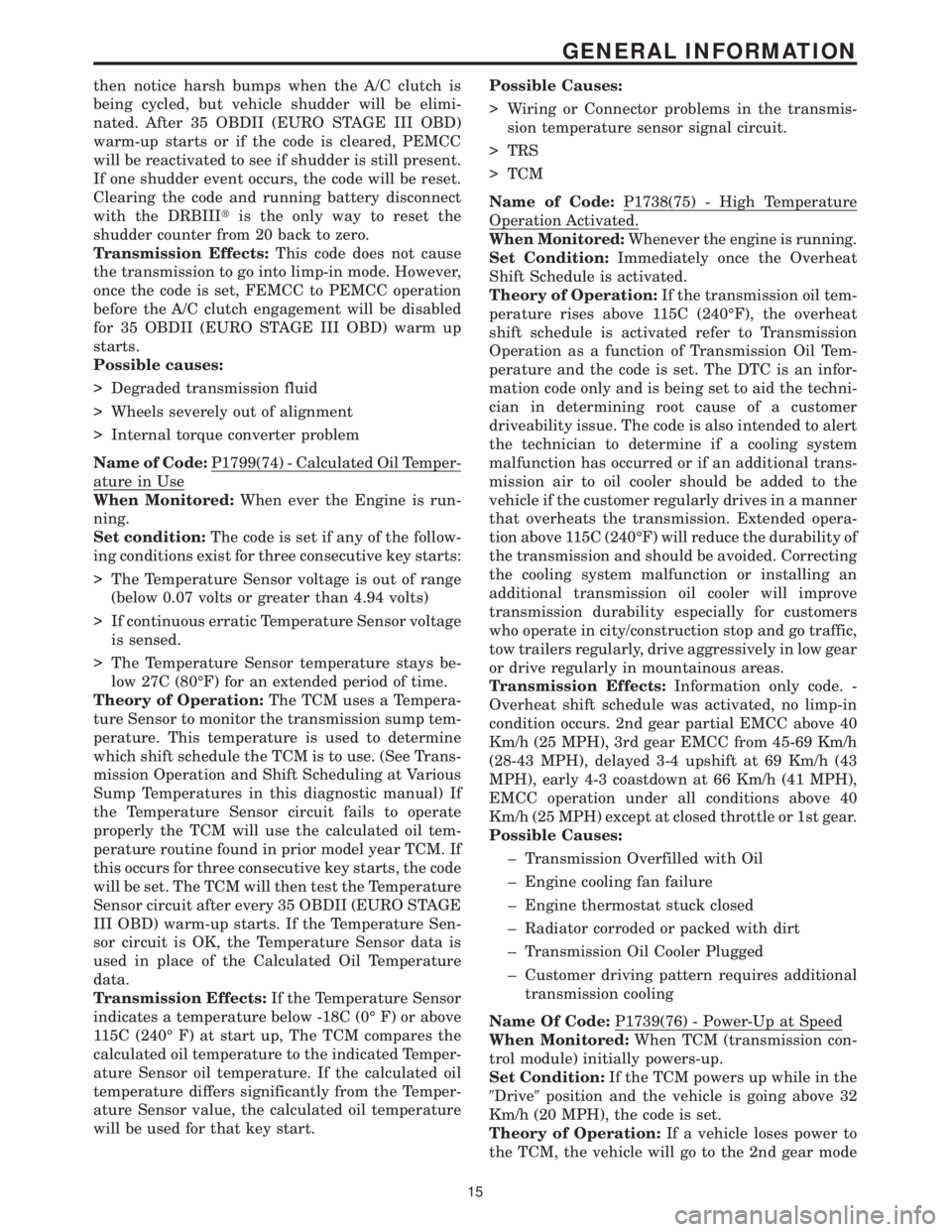
Name of Code:P1799(74) - Calculated Oil Temper-
ature in Use
When Monitored:When ever the Engine is run-
ning.
Set condition:The code is set if any of the follow-
ing conditions exist for three consecutive key starts:
> The Temperature Sensor voltage is out of range
(below 0.07 volts or greater than 4.94 volts)
> If continuous erratic Temperature Sensor voltage
is sensed.
> The Temperature Sensor temperature stays be-
low 27C (80ÉF) for an extended period of time.
Theory of Operation:The TCM uses a Tempera-
ture Sensor to monitor the transmission sump tem-
perature. This temperature is used to determine
which shift schedule the TCM is to use. (See Trans-
mission Operation and Shift Scheduling at Various
Sump Temperatures in this diagnostic manual) If
the Temperature Sensor circuit fails to operate
properly the TCM will use the calculated oil tem-
perature routine found in prior model year TCM. If
this occurs for three consecutive key starts, the code
will be set. The TCM will then test the Temperature
Sensor circuit after every 35 OBDII (EURO STAGE
III OBD) warm-up starts. If the Temperature Sen-
sor circuit is OK, the Temperature Sensor data is
used in place of the Calculated Oil Temperature
data.
Transmission Effects:If the Temperature Sensor
indicates a temperature below -18C (0É F) or above
115C (240É F) at start up, The TCM compares the
calculated oil temperature to the indicated Temper-
ature Sensor oil temperature. If the calculated oil
temperature differs significantly from the Temper-
ature Sensor value, the calculated oil temperature
will be used for that key start.Possible Causes:
> Wiring or Connector problems in the transmis-
sion temperature sensor signal circuit.
> TRS
> TCM
Name of Code:P1738(75) - High Temperature
Operation Activated.
When Monitored:Whenever the engine is running.
Set Condition:Immediately once the Overheat
Shift Schedule is activated.
Theory of Operation:If the transmission oil tem-
perature rises above 115C (240ÉF), the overheat
shift schedule is activated refer to Transmission
Operation as a function of Transmission Oil Tem-
perature and the code is set. The DTC is an infor-
mation code only and is being set to aid the techni-
cian in determining root cause of a customer
driveability issue. The code is also intended to alert
the technician to determine if a cooling system
malfunction has occurred or if an additional trans-
mission air to oil cooler should be added to the
vehicle if the customer regularly drives in a manner
that overheats the transmission. Extended opera-
tion above 115C (240ÉF) will reduce the durability of
the transmission and should be avoided. Correcting
the cooling system malfunction or installing an
additional transmission oil cooler will improve
transmission durability especially for customers
who operate in city/construction stop and go traffic,
tow trailers regularly, drive aggressively in low gear
or drive regularly in mountainous areas.
Transmission Effects:Information only code. -
Overheat shift schedule was activated, no limp-in
condition occurs. 2nd gear partial EMCC above 40
Km/h (25 MPH), 3rd gear EMCC from 45-69 Km/h
(28-43 MPH), delayed 3-4 upshift at 69 Km/h (43
MPH), early 4-3 coastdown at 66 Km/h (41 MPH),
EMCC operation under all conditions above 40
Km/h (25 MPH) except at closed throttle or 1st gear.
Possible Causes:
± Transmission Overfilled with Oil
± Engine cooling fan failure
± Engine thermostat stuck closed
± Radiator corroded or packed with dirt
± Transmission Oil Cooler Plugged
± Customer driving pattern requires additional
transmission cooling
Name Of Code:P1739(76) - Power-Up at Speed
When Monitored:When TCM (transmission con-
trol module) initially powers-up.
Set Condition:If the TCM powers up while in the
9Drive9position and the vehicle is going above 32
Km/h (20 MPH), the code is set.
Theory of Operation:If a vehicle loses power to
the TCM, the vehicle will go to the 2nd gear mode
15
GENERAL INFORMATION
Page 4234 of 4284
Symptom:
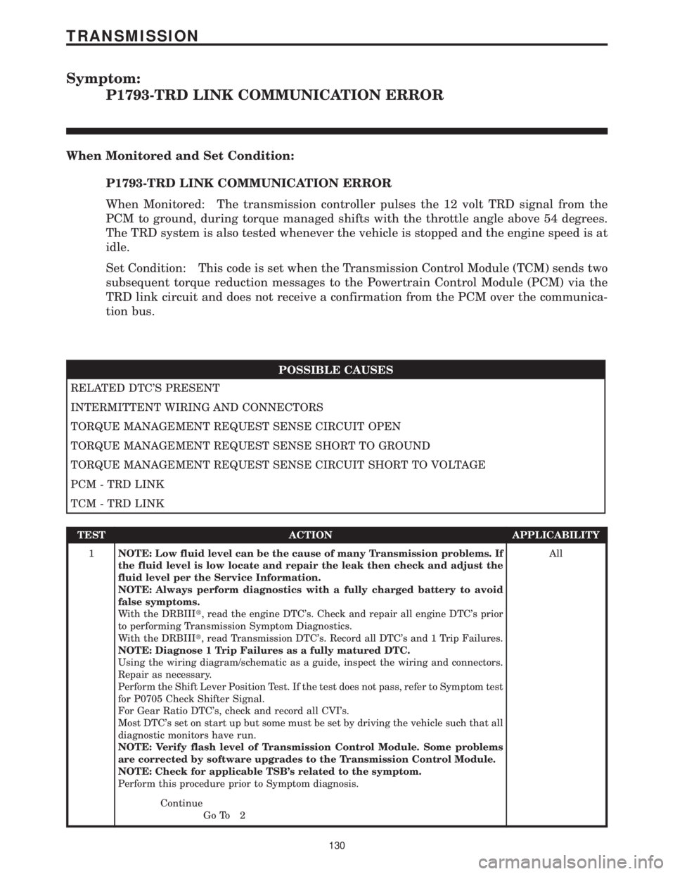
P1793-TRD LINK COMMUNICATION ERROR
When Monitored and Set Condition:
P1793-TRD LINK COMMUNICATION ERROR
When Monitored: The transmission controller pulses the 12 volt TRD signal from the
PCM to ground, during torque managed shifts with the throttle angle above 54 degrees.
The TRD system is also tested whenever the vehicle is stopped and the engine speed is at
idle.
Set Condition: This code is set when the Transmission Control Module (TCM) sends two
subsequent torque reduction messages to the Powertrain Control Module (PCM) via the
TRD link circuit and does not receive a confirmation from the PCM over the communica-
tion bus.
POSSIBLE CAUSES
RELATED DTC'S PRESENT
INTERMITTENT WIRING AND CONNECTORS
TORQUE MANAGEMENT REQUEST SENSE CIRCUIT OPEN
TORQUE MANAGEMENT REQUEST SENSE SHORT TO GROUND
TORQUE MANAGEMENT REQUEST SENSE CIRCUIT SHORT TO VOLTAGE
PCM - TRD LINK
TCM - TRD LINK
TEST ACTION APPLICABILITY
1NOTE: Low fluid level can be the cause of many Transmission problems. If
the fluid level is low locate and repair the leak then check and adjust the
fluid level per the Service Information.
NOTE: Always perform diagnostics with a fully charged battery to avoid
false symptoms.
With the DRBIIIt, read the engine DTC's. Check and repair all engine DTC's prior
to performing Transmission Symptom Diagnostics.
With the DRBIIIt, read Transmission DTC's. Record all DTC's and 1 Trip Failures.
NOTE: Diagnose 1 Trip Failures as a fully matured DTC.
Using the wiring diagram/schematic as a guide, inspect the wiring and connectors.
Repair as necessary.
Perform the Shift Lever Position Test. If the test does not pass, refer to Symptom test
for P0705 Check Shifter Signal.
For Gear Ratio DTC's, check and record all CVI's.
Most DTC's set on start up but some must be set by driving the vehicle such that all
diagnostic monitors have run.
NOTE: Verify flash level of Transmission Control Module. Some problems
are corrected by software upgrades to the Transmission Control Module.
NOTE: Check for applicable TSB's related to the symptom.
Perform this procedure prior to Symptom diagnosis.All
Continue
Go To 2
130
TRANSMISSION