2001 CHRYSLER VOYAGER stop start
[x] Cancel search: stop startPage 3695 of 4284
OPERATION
The compressor is driven by the engine through an
electric clutch, drive pulley and belt arrangement.
The compressor is lubricated by refrigerant oil that is
circulated throughout the refrigerant system with the
refrigerant. The compressor draws in low-pressure
refrigerant vapor from the evaporator through its
suction port. It then compresses the refrigerant into
a high-pressure, high-temperature refrigerant vapor.
The compressor pumps high-pressure refrigerant
vapor to the condenser through the compressor dis-
charge port. The mechanical high pressure relief
valve is designed to vent refrigerant from the system
to protect against damage to the compressor or other
system components, caused by condenser air flow
restrictions or an overcharge of refrigerant. The valve
only vents enough refrigerant to reduce the system
pressure, then re-seats itself. The valve opens at a
discharge pressure of 3445 to 4135 kPA (500 to 600
psi) or above, and closes when a minimum discharge
pressure of 2756 kPa (400 psi) is reached.
DIAGNOSIS AND TESTING - COMPRESSOR
NOISE
Excessive noise while the air conditioning compres-
sor is operating can be caused by loose compressor
mounts, a loose compressor clutch, or high operating
pressures in the refrigerant system. Verify compres-
sor drive belt condition, proper compressor mounting,
correct refrigerant charge level, and compressor head
pressure before compressor repair is performed.
With the close tolerances within the compressor, it
is possible to experience a temporary lockup. The
longer the compressor is inactive, the more likely the
condition is to occur. This condition is the result of
normal refrigerant migration within the refrigerant
system caused by ambient temperature changes. The
refrigerant migration may wash the refrigerant oil
out of the compressor.
NOTE: Prior to a vehicle being removed from ser-
vice or stored for more than two weeks, the com-
pressor should be operated to ensure adequate
refrigerant oil distribution throughout the system
components. Turn on the air conditioner for a min-
imum of five minutes with outside air and the high-
est blower speed selected.
BELT NOISE
If the compressor drive belt slips at initial start-up,
it does not necessarily mean the compressor has
failed. The following procedure can be used to iden-
tify a compressor drive belt noise problem.
²Start the vehicle and run at idle.²Turn the air conditioner On and listen for belt
squeal.
²If belt squeal is heard, turn the air conditioner
Off immediately.
If the belt squeal stops when the air conditioner is
turned Off, perform the following repair procedures.
(1) Using an appropriate sized oil filter wrench or
a strap wrench, grasp the outer diameter of the com-
pressor clutch hub. While facing the compressor,
rotate the hub clockwise, then counterclockwise. If
the hub rotates, proceed to the next step. If the hub
will not rotate, the compressor is internally damaged,
and must be replaced.
(2) Turn the hub clockwise five complete revolu-
tions and remove the tool.
(3) Start the vehicle and run at idle.
(4) Turn the air conditioner On. Observe the com-
pressor and the system for normal operation, noting
cooling performance and noise levels. Operate for five
minutes before turning the air conditioner Off. If
acceptable cooling performance is observed during
compressor operation, the compressor does not need
to be replaced.
(5) Inspect the drive belt for wear, damage, and
proper tension. (Refer to 7 - COOLING/ACCESSORY
DRIVE/DRIVE BELTS - DIAGNOSIS AND TEST-
ING).
REMOVAL - COMPRESSOR
WARNING: REFER TO THE APPLICABLE WARN-
INGS AND CAUTIONS FOR THIS SYSTEM BEFORE
PERFORMING THE FOLLOWING OPERATION.
(Refer to 24 - HEATING & AIR CONDITIONING/
PLUMBING - FRONT - WARNING - A/C PLUMBING)
and (Refer to 24 - HEATING & AIR CONDITIONING/
PLUMBING - FRONT - CAUTION - A/C PLUMBING).
(1) Recover the refrigerant from the refrigerant
system. (Refer to 24 - HEATING & AIR CONDI-
TIONING/PLUMBING - FRONT/REFRIGERANT -
STANDARD PROCEDURE - REFRIGERANT
RECOVERY).
(2) Disconnect and isolate the battery negative
cable.
(3) Remove the nut that secures the suction line
fitting to the top of the compressor.
(4) Disconnect the suction line fitting from the
compressor suction port.
(5) Remove the seal from the suction line fitting
and discard.
(6) Install plugs in, or tape over the opened suc-
tion line fitting and the compressor suction port.
(7) Remove the nut that secures the discharge line
fitting to the top of the compressor.
(8) Disconnect the discharge line fitting from the
compressor discharge port.
RSPLUMBING - FRONT24-65
COMPRESSOR (Continued)
Page 3758 of 4284
LEAK DETECTION PUMP MONITOR
The leak detection assembly incorporates two pri-
mary functions: it must detect a leak in the evapora-
tive system and seal the evaporative system so the
leak detection test can be run.
The primary components within the assembly are:
A three port solenoid that activates both of the func-
tions listed above; a pump which contains a switch,
two check valves and a spring/diaphragm, a canister
vent valve (CVV) seal which contains a spring loaded
vent seal valve.
Immediately after a cold start, between predeter-
mined temperature thresholds limits, the three port
solenoid is briefly energized. This initializes the
pump by drawing air into the pump cavity and also
closes the vent seal. During non test conditions the
vent seal is held open by the pump diaphragm
assembly which pushes it open at the full travel posi-
tion. The vent seal will remain closed while the
pump is cycling due to the reed switch triggering of
the three port solenoid that prevents the diaphragm
assembly from reaching full travel. After the brief
initialization period, the solenoid is de-energized
allowing atmospheric pressure to enter the pump
cavity, thus permitting the spring to drive the dia-
phragm which forces air out of the pump cavity and
into the vent system. When the solenoid is energized
and de energized, the cycle is repeated creating flow
in typical diaphragm pump fashion. The pump is con-
trolled in 2 modes:
Pump Mode:The pump is cycled at a fixed rate to
achieve a rapid pressure build in order to shorten the
overall test length.
Test Mode:The solenoid is energized with a fixed
duration pulse. Subsequent fixed pulses occur when
the diaphragm reaches the Switch closure point.
The spring in the pump is set so that the system
will achieve an equalized pressure of about 7.5º H20.
The cycle rate of pump strokes is quite rapid as the
system begins to pump up to this pressure. As the
pressure increases, the cycle rate starts to drop off. If
there is no leak in the system, the pump would even-
tually stop pumping at the equalized pressure. If
there is a leak, it will continue to pump at a rate rep-
resentative of the flow characteristic of the size of the
leak. From this information we can determine if the
leak is larger than the required detection limit (cur-
rently set at .020º orifice by CARB). If a leak is
revealed during the leak test portion of the test, the
test is terminated at the end of the test mode and no
further system checks will be performed.
After passing the leak detection phase of the test,
system pressure is maintained by turning on the
LDP's solenoid until the purge system is activated.
Purge activation in effect creates a leak. The cycle
rate is again interrogated and when it increases dueto the flow through the purge system, the leak check
portion of the diagnostic is complete.
The canister vent valve will unseal the system
after completion of the test sequence as the pump
diaphragm assembly moves to the full travel position.
Evaporative system functionality will be verified by
using the stricter evap purge flow monitor. At an
appropriate warm idle the LDP will be energized to
seal the canister vent. The purge flow will be clocked
up from some small value in an attempt to see a
shift in the 02 control system. If fuel vapor, indicated
by a shift in the 02 control, is present the test is
passed. If not, it is assumed that the purge system is
not functioning in some respect. The LDP is again
turned off and the test is ended.
DESCRIPTION - HIGH AND LOW LIMITS
The PCM compares input signal voltages from each
input device with established high and low limits for
the device. If the input voltage is not within limits
and other criteria are met, the PCM stores a diagnos-
tic trouble code in memory. Other diagnostic trouble
code criteria might include engine RPM limits or
input voltages from other sensors or switches that
must be present before verifying a diagnostic trouble
code condition.
OPERATION - SYSTEM
The Powertrain Control Module (PCM) monitors
many different circuits in the fuel injection, ignition,
emission and engine systems. If the PCM senses a
problem with a monitored circuit often enough to
indicate an actual problem, it stores a Diagnostic
Trouble Code (DTC) in the PCM's memory. If the
code applies to a non-emissions related component or
system, and the problem is repaired or ceases to
exist, the PCM cancels the code after 40 warmup
cycles. Diagnostic trouble codes that affect vehicle
emissions illuminate the Malfunction Indicator Lamp
(MIL). Refer to Malfunction Indicator Lamp in this
section.
Certain criteria must be met before the PCM
stores a DTC in memory. The criteria may be a spe-
cific range of engine RPM, engine temperature,
and/or input voltage to the PCM.
The PCM might not store a DTC for a monitored
circuit even though a malfunction has occurred. This
may happen because one of the DTC criteria for the
circuit has not been met.For example, assume the
diagnostic trouble code criteria requires the PCM to
monitor the circuit only when the engine operates
between 750 and 2000 RPM. Suppose the sensor's
output circuit shorts to ground when engine operates
above 2400 RPM (resulting in 0 volt input to the
PCM). Because the condition happens at an engine
25 - 8 EMISSIONS CONTROLRS
EMISSIONS CONTROL (Continued)
Page 3765 of 4284
ORVR
OPERATION
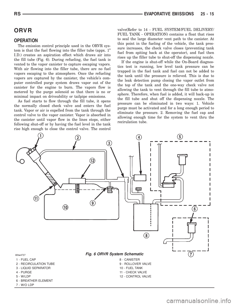
The emission control principle used in the ORVR sys-
tem is that the fuel flowing into the filler tube (appx. 1º
I.D.) creates an aspiration effect which draws air into
the fill tube (Fig. 6). During refueling, the fuel tank is
vented to the vapor canister to capture escaping vapors.
With air flowing into the filler tube, there are no fuel
vapors escaping to the atmosphere. Once the refueling
vapors are captured by the canister, the vehicle's com-
puter controlled purge system draws vapor out of the
canister for the engine to burn. The vapors flow is
metered by the purge solenoid so that there is no or
minimal impact on driveability or tailpipe emissions.
As fuel starts to flow through the fill tube, it opens
the normally closed check valve and enters the fuel
tank. Vapor or air is expelled from the tank through the
control valve to the vapor canister. Vapor is absorbed in
the canister until vapor flow in the lines stops, either
following shut-off or by having the fuel level in the tank
rise high enough to close the control valve. The controlvalve(Refer to 14 - FUEL SYSTEM/FUEL DELIVERY/
FUEL TANK - OPERATION) contains a float that rises
to seal the large diameter vent path to the canister. At
this point in the fueling of the vehicle, the tank pres-
sure increases, the check valve closes (preventing tank
fuel from spiting back at the operator), and fuel then
rises up the filler tube to shut-off the dispensing nozzle.
If the engine is shut-off while the On-Board diagnos-
tics test is running, low level tank pressure can be
trapped in the fuel tank and fuel can not be added to
the tank until the pressure is relieved. This is due to
the leak detection pump closing the vapor outlet from
the top of the tank and the one-way check valve not
allowing the tank to vent through the fill tube to atmo-
sphere. Therefore, when fuel is added, it will back-up in
the fill tube and shut off the dispensing nozzle. The
pressure can be eliminated in two ways: 1. Vehicle
purge must be activated and for a long enough period to
eliminate the pressure. 2. Removing the fuel cap and
allowing enough time for the system to vent thru the
recirulation tube.
Fig. 6 ORVR System Schematic
1 - FUEL CAP
2 - RECIRCULATION TUBE
3 - LIQUID SEPARATOR
4 - PURGE
5 - W/LDP
6 - BREATHER ELEMENT
7 - W/O LDP8 - CANISTER
9 - ROLLOVER VALVE
10 - FUEL TANK
11 - CHECK VALVE
12 - CONTROL VALVE
RSEVAPORATIVE EMISSIONS25-15
Page 3775 of 4284
Major Monitors. If the Task Manager cannot run a
Global Good Trip because a component fault is stop-
ping the monitor from running, it will attempt to
count an Alternate Good Trip.
The Task Manager counts an Alternate Good Trip
for Comprehensive components when the following
conditions are met:
²Two minutes of engine run time
²No other faults occur
The Task Manager counts an Alternate Good Trip
for a Major Monitor when the monitor runs and
passes. Only the Major Monitor that failed needs to
pass to count an Alternate Good Trip.
Warm-Up Cycles
Once the MIL has been extinguished by the Good
Trip Counter, the PCM automatically switches to a
Warm-Up Cycle Counter that can be viewed on the
DRBIIIt. Warm-Up Cycles are used to erase DTCs
and Freeze Frames. Forty Warm-Up cycles must
occur in order for the PCM to self-erase a DTC and
Freeze Frame. A Warm-Up Cycle is defined as fol-
lows:
²Engine coolant temperature must start below
and rise above 160É F
²Engine coolant temperature must rise by 40É F
²No further faults occur
Freeze Frame Data Storage
Once a failure occurs, the Task Manager records
several engine operating conditions and stores it in a
Freeze Frame. The Freeze Frame is considered one
frame of information taken by an on-board data
recorder. When a fault occurs, the PCM stores the
input data from various sensors so that technicians
can determine under what vehicle operating condi-
tions the failure occurred.
The data stored in Freeze Frame is usually
recorded when a system fails the first time for two
trip faults. Freeze Frame data will only be overwrit-
ten by a different fault with a higher priority.
CAUTION: Erasing DTCs, either with the DRBIIIT;or
by disconnecting the battery, also clears all Freeze
Frame data.
Similar Conditions Window
The Similar Conditions Window displays informa-
tion about engine operation during a monitor. Abso-
lute MAP (engine load) and Engine RPM are stored
in this window when a failure occurs. There are two
different Similar conditions Windows: Fuel System
and Misfire.
FUEL SYSTEM
²Fuel System Similar Conditions WindowÐ
An indicator that 'Absolute MAP When Fuel Sys Fail'
and 'RPM When Fuel Sys Failed' are all in the samerange when the failure occurred. Indicated by switch-
ing from 'NO' to 'YES'.
²Absolute MAP When Fuel Sys FailÐ The
stored MAP reading at the time of failure. Informs
the user at what engine load the failure occurred.
²Absolute MAPÐ A live reading of engine load
to aid the user in accessing the Similar Conditions
Window.
²RPM When Fuel Sys FailÐ The stored RPM
reading at the time of failure. Informs the user at
what engine RPM the failure occurred.
²Engine RPMÐ A live reading of engine RPM
to aid the user in accessing the Similar Conditions
Window.
²Adaptive Memory FactorÐ The PCM utilizes
both Short Term Compensation and Long Term Adap-
tive to calculate the Adaptive Memory Factor for
total fuel correction.
²Upstream O2S VoltsÐ A live reading of the
Oxygen Sensor to indicate its performance. For
example, stuck lean, stuck rich, etc.
²SCW Time in Window (Similar Conditions
Window Time in Window)Ð A timer used by the
PCM that indicates that, after all Similar Conditions
have been met, if there has been enough good engine
running time in the SCW without failure detected.
This timer is used to increment a Good Trip.
²Fuel System Good Trip CounterÐATrip
Counter used to turn OFF the MIL for Fuel System
DTCs. To increment a Fuel System Good Trip, the
engine must be in the Similar Conditions Window,
Adaptive Memory Factor must be less than cali-
brated threshold and the Adaptive Memory Factor
must stay below that threshold for a calibrated
amount of time.
²Test Done This TripÐ Indicates that the
monitor has already been run and completed during
the current trip.
MISFIRE
²Same Misfire Warm-Up StateÐ Indicates if
the misfire occurred when the engine was warmed up
(above 160É F).
²In Similar Misfire WindowÐ An indicator
that 'Absolute MAP When Misfire Occurred' and
'RPM When Misfire Occurred' are all in the same
range when the failure occurred. Indicated by switch-
ing from 'NO' to 'YES'.
²Absolute MAP When Misfire OccurredÐ
The stored MAP reading at the time of failure.
Informs the user at what engine load the failure
occurred.
²Absolute MAPÐ A live reading of engine load
to aid the user in accessing the Similar Conditions
Window.
RSON-BOARD DIAGNOSTICS25-25
TASK MANAGER (Continued)
Page 3784 of 4284
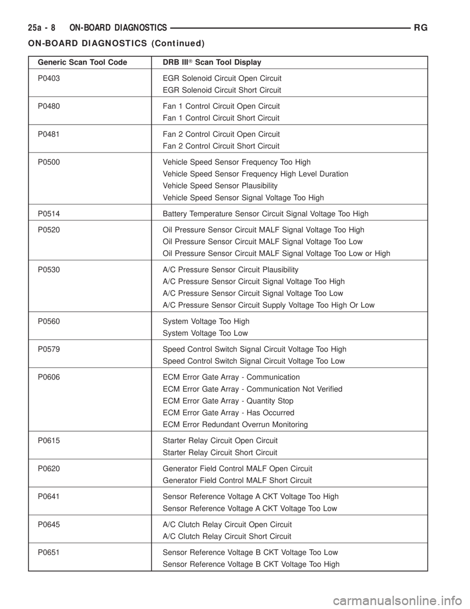
Generic Scan Tool Code DRB IIITScan Tool Display
P0403 EGR Solenoid Circuit Open Circuit
EGR Solenoid Circuit Short Circuit
P0480 Fan 1 Control Circuit Open Circuit
Fan 1 Control Circuit Short Circuit
P0481 Fan 2 Control Circuit Open Circuit
Fan 2 Control Circuit Short Circuit
P0500 Vehicle Speed Sensor Frequency Too High
Vehicle Speed Sensor Frequency High Level Duration
Vehicle Speed Sensor Plausibility
Vehicle Speed Sensor Signal Voltage Too High
P0514 Battery Temperature Sensor Circuit Signal Voltage Too High
P0520 Oil Pressure Sensor Circuit MALF Signal Voltage Too High
Oil Pressure Sensor Circuit MALF Signal Voltage Too Low
Oil Pressure Sensor Circuit MALF Signal Voltage Too Low or High
P0530 A/C Pressure Sensor Circuit Plausibility
A/C Pressure Sensor Circuit Signal Voltage Too High
A/C Pressure Sensor Circuit Signal Voltage Too Low
A/C Pressure Sensor Circuit Supply Voltage Too High Or Low
P0560 System Voltage Too High
System Voltage Too Low
P0579 Speed Control Switch Signal Circuit Voltage Too High
Speed Control Switch Signal Circuit Voltage Too Low
P0606 ECM Error Gate Array - Communication
ECM Error Gate Array - Communication Not Verified
ECM Error Gate Array - Quantity Stop
ECM Error Gate Array - Has Occurred
ECM Error Redundant Overrun Monitoring
P0615 Starter Relay Circuit Open Circuit
Starter Relay Circuit Short Circuit
P0620 Generator Field Control MALF Open Circuit
Generator Field Control MALF Short Circuit
P0641 Sensor Reference Voltage A CKT Voltage Too High
Sensor Reference Voltage A CKT Voltage Too Low
P0645 A/C Clutch Relay Circuit Open Circuit
A/C Clutch Relay Circuit Short Circuit
P0651 Sensor Reference Voltage B CKT Voltage Too Low
Sensor Reference Voltage B CKT Voltage Too High
25a - 8 ON-BOARD DIAGNOSTICSRG
ON-BOARD DIAGNOSTICS (Continued)
Page 3798 of 4284
3.2.3 OTHER CONTROLS
CHARGING SYSTEM
The charging system is turned on when the
engine is started and ASD relay energized. When
the ASD relay is on, ASD output voltage is supplied
to the ASD sense circuit at the PCM. This voltage is
connected in some cases, through the PCM and
supplied to one of the generator field terminals
(Gen Source +). All others, the Gen field is con-
nected directly to the ASD output voltage. The
amount of current produced by the generator is
controlled by the Electronic Voltage Regulator
(EVR) circuitry, in the PCM. Battery temperature is
determined from IAT. This temperature along with
sensed line voltage, is used by the PCM to vary the
battery charging rate. This is done by cycling the
ground path to the other generator field terminal
(Gen field driver).
SPEED CONTROL SYSTEM
The PCM controls vehicle speed by operation of
the speed control servo vacuum and vent solenoids.
Energizing the vacuum solenoid applies vacuum to
the servo to increase throttle position. Operation of
the vent solenoid slowly releases the vacuum allow-
ing throttle position to decrease. A special dump
solenoid allows immediate release of throttle posi-
tion caused by braking, cruise control switch turned
off, shifting into neutral, excessive RPM (tires spin-
ning) or ignition off.
LEAK DETECTION PUMP SYSTEM (IF EQUIPPED)
The leak detection pump is a device that pressur-
izes the evaporative system to determine if there
are any leaks. When certain conditions are met, the
PCM will activate the pump and start counting
pump strokes. If the pump stops within a calibrated
number of strokes, the system is determined to be
normal. If the pump does not stop or stops too soon,
a DTC will be set.
3.2.4 PCM OPERATING MODES
As input signals to the PCM change, the PCM
adjusts its response to output devices. For example,
the PCM must calculate a different injector pulse
width and ignition timing for idle than it does for
wide open throttle. There are several different
modes of operation that determine how the PCM
responds to the various input signals.
There are two types of engine control operation:
open loopandclosed loop.
Inopen loopoperation, the PCM receives input
signals and responds according to preset program-
ming. Inputs from the heated oxygen sensors are
not monitored.Inclosed loopoperation, the PCM monitors the
inputs from the heated oxygen sensors. This input
indicates to the PCM whether or not the calculated
injector pulse width results in the ideal air-fuel
ratio of 14.7 parts air to 1 part fuel. By monitoring
the exhaust oxygen content through the oxygen
sensor, the PCM can fine tune injector pulse width.
Fine tuning injector pulse width allows the PCM to
achieve the lowest emission levels while maintain-
ing optimum fuel economy.
The engine start-up (crank), engine warm-up,
and wide open throttle modes are open loop modes.
Under most operating conditions, closed loop modes
occur with the engine at operating temperature.
IGNITION SWITCH ON (ENGINE OFF) MODE
When the ignition switch activates the fuel injec-
tion system, the following actions occur:
1. The PCM determines atmospheric air pressure
from the MAP sensor input to determine basic
fuel strategy.
2. The PCM monitors the engine coolant tempera-
ture sensor and throttle position sensor input.
The PCM modifies fuel strategy based on this
input.
When the key is in the on position and the engine
is not running (zero rpm), the auto shutdown relay
and fuel pump relay are not energized. Therefore,
voltage is not supplied to the fuel pump, ignition
coil, and fuel injectors.
Engine Start-up ModeÐ This is an open loop
mode. The following actions occur when the starter
motor is engaged:
1. The auto shutdown and fuel pump relays are
energized. If the PCM does not receive the cam-
shaft and crankshaft signal within approxi-
mately one second, these relays are de-
energized.
2. The PCM energizes all fuel injectors until it
determines crankshaft position from the cam-
shaft and crankshaft signals. The PCM deter-
mines crankshaft position within one engine
revolution. After the camshaft position has been
determined, the PCM energizes the fuel injectors
in sequence. The PCM adjusts the injector pulse
width and synchronizes the fuel injectors by
controlling the fuel injectors' ground paths.
3. Once the engine idles within 64 rpm of its target
engine speed, the PCM compares the current
MAP sensor value with the value received dur-
ing the ignition switch on (zero rpm) mode. A
diagnostic trouble code is written to PCM mem-
ory if a minimum difference between the two
values is not found.
4
GENERAL INFORMATION
Page 3800 of 4284
message the PCM will terminate engine operation,
or allow the engine to continue to operate.
3.2.7 SKIM ON-BOARD DIAGNOSTICS
The SKIM has been programmed to transmit and
monitor many different coded messages as well as
PCI Bus messages. This monitoring is called On
Board Diagnosis.
Certain criteria must be met for a diagnostic
trouble code to be entered into the SKIM memory.
The criteria may be a range of; Input voltage, PCI
Bus message, or coded messages to the SKIM. If all
of the criteria for monitoring a circuit or function
are met and a fault is sensed, a diagnostic trouble
code will be stored in the SKIM memory.
3.2.8 SKIS OPERATION
When ignition power is supplied to the SKIM, the
SKIM performs an internal self-test. After the self-
test is completed, the SKIM energizes the antenna
(this activates the transponder chip) and sends a
challenge to the transponder chip. The transponder
chip responds to the challenge by generating an
encrypted response message using the following:
Secret Key -This is an electronically stored
value (identification number) that is unique to each
SKIS. The secret key is stored in the SKIM, PCM
and all ignition key transponders.
Challenge- This is a random number that is
generated by the SKIM at each ignition key cycle.
The secret key and challenge are the two vari-
ables used in the algorithm that produces the
encrypted response message. The transponder uses
the crypto algorithm to receive, decode and respond
to the message sent by the SKIM. After responding
to the coded message, the transponder sends a
transponder I.D. message to the SKIM. The SKIM
compares the transponder I.D. to the available valid
key codes in the SKIM memory (8 key maximum at
any one time). After validating the key ignition the
SKIM sends a PCI Bus message called a Seed
Request to the engine controller then waits for a
PCM response. If the PCM does not respond, the
SKIM will send the seed request again. After three
failed attempts the SKIM will stop sending the seed
request and store a trouble code. If the PCM sends
a seed response, the SKIM sends a valid/invalid key
message to the PCM. This is an encrypted message
that is generated using the following:
VIN -Vehicle Identification Number
Seed -This is a random number that is generated
by the PCM at each ignition key cycle.
The VIN and seed are the two variables used in
the rolling code algorithm that encrypts the valid/
invalid key message. The PCM uses the rolling code
algorithm to receive, decode and respond to the
valid/invalid key message sent by the SKIM. Aftersending the valid/invalid key message the SKIM
waits 3.5 seconds for a PCM status message from
the PCM. If the PCM does not respond with a valid
key message to the SKIM, a fault is detected and a
trouble code is stored.
The SKIS incorporates a VTSS LED located on
the instrument panel upper cover. The LED re-
ceives switched ignition voltage and is hardwired to
the body control module. The LED is actuated when
the SKIM sends a PCI Bus message to the body
controller requesting the LED on. The body control-
ler then provides the ground for the LED. The
SKIM will request VTSS LED operation for the
following:
± bulb checks at ignition on
± to alert the vehicle operator to a SKIS mal-
function
± customer key programming mode
For all faults except transponder faults and VTSS
LED remains on steady. In the event of a transpon-
der fault the LED flashes at a rate of 1 Hz (once per
second). If a fault is present the LED will remain on
or flashing for the complete ignition cycle. If a fault
is stored in SKIM memory which prevents the
system from operating properly, the PCM will allow
the engine to start and run (for 2 seconds) up to six
times. After the sixth attempt, the PCM disables
the starter relay until the fault is corrected.
3.2.9 PROGRAMMING THE POWERTRAIN
CONTROL MODULE
Important Note:Before replacing the PCM for a
failed driver, control circuit or ground circuit, be
sure to check the related component/circuit integ-
rity for failures not detected due to a double fault in
the circuit. Most PCM driver/control circuit failures
are caused by internal failure to components (i.e.
12-volt pull-ups, drivers and ground sensors). These
failures are difficult to detect when a double fault
has occurred and only one DTC has set.
NOTE: IF THE PCM AND THE SKIM ARE
REPLACED AT THE SAME TIME, PROGRAM
THE VIN INTO THE PCM FIRST. ALL VEHICLE
KEYS WILL THEN NEED TO BE REPLACED
AND PROGRAMMED TO THE NEW SKIM.
The SKIS Secret Key is an I.D. code that is
unique to each SKIS. This code is programmed and
stored in the SKIM, engine controller and transpon-
der chip (ignition key). When replacing the PCM it
is necessary to program the secret key into the
PCM.
1. Turn the ignition on (transmission in park/
neutral).
2. Use the DRB and select THEFT ALARM, SKIM
then MISCELLANEOUS.
6
GENERAL INFORMATION
Page 3812 of 4284
Symptom:
P1594-CHARGING SYSTEM VOLTAGE TOO HIGH
When Monitored and Set Condition:
P1594-CHARGING SYSTEM VOLTAGE TOO HIGH
When Monitored: The engine running. The engine speed greater than 380 RPM.
Set Condition: Battery voltage is 1 volt greater than desired system voltage.
POSSIBLE CAUSES
TARGET VOLTAGE DIFFERS FROM BATTERY VOLTAGE
INTERMITTENT CONDITION
GENERATOR FIELD DRIVER CIRCUIT SHORTED TO GROUND
GENERATOR FIELD
POWERTRAIN CONTROL MODULE
TEST ACTION APPLICABILITY
1Note: Battery must be fully charged.
Note: Generator Belt tension and condition must be checked before con-
tinuing.
Turn the ignition on.
With DRBIIIt, actuate the Generator Field Driver.
With a 12-volt test light connected to ground, backprobe the Generator Field Driver
circuit in the back of Generator Field harness connector.
Does the test light illuminate brightly and flash?All
Ye s®Go To 2
No®Go To 5
2 With DRBIIIt, stop all actuation.
Turn the ignition on.
With DRBIIIt, read the Target Charging voltage.
Is the Target Charging voltage above 13 volts?All
Ye s®Go To 3
No®Go To 4
3 Start the engine.
With the DRBIIIt, manually set the engine speed to 1600 RPM.
With DRBIIIt, read both the Battery voltage and the Target Charging voltage.
Compare the Target Charging Voltage to the Battery Voltage reading.
Monitor voltage for 5 minutes, if necessary. Look for a 1.0 volt difference or more.
Was there more than a 1.0 volt difference?All
Ye s®Replace the Powertrain Control Module in accordance with the
Service Information.
Perform POWERTRAIN VERIFICATION TEST VER - 3.
No®Go To 4
18
CHARGING