2001 CHRYSLER VOYAGER stop start
[x] Cancel search: stop startPage 3891 of 4284
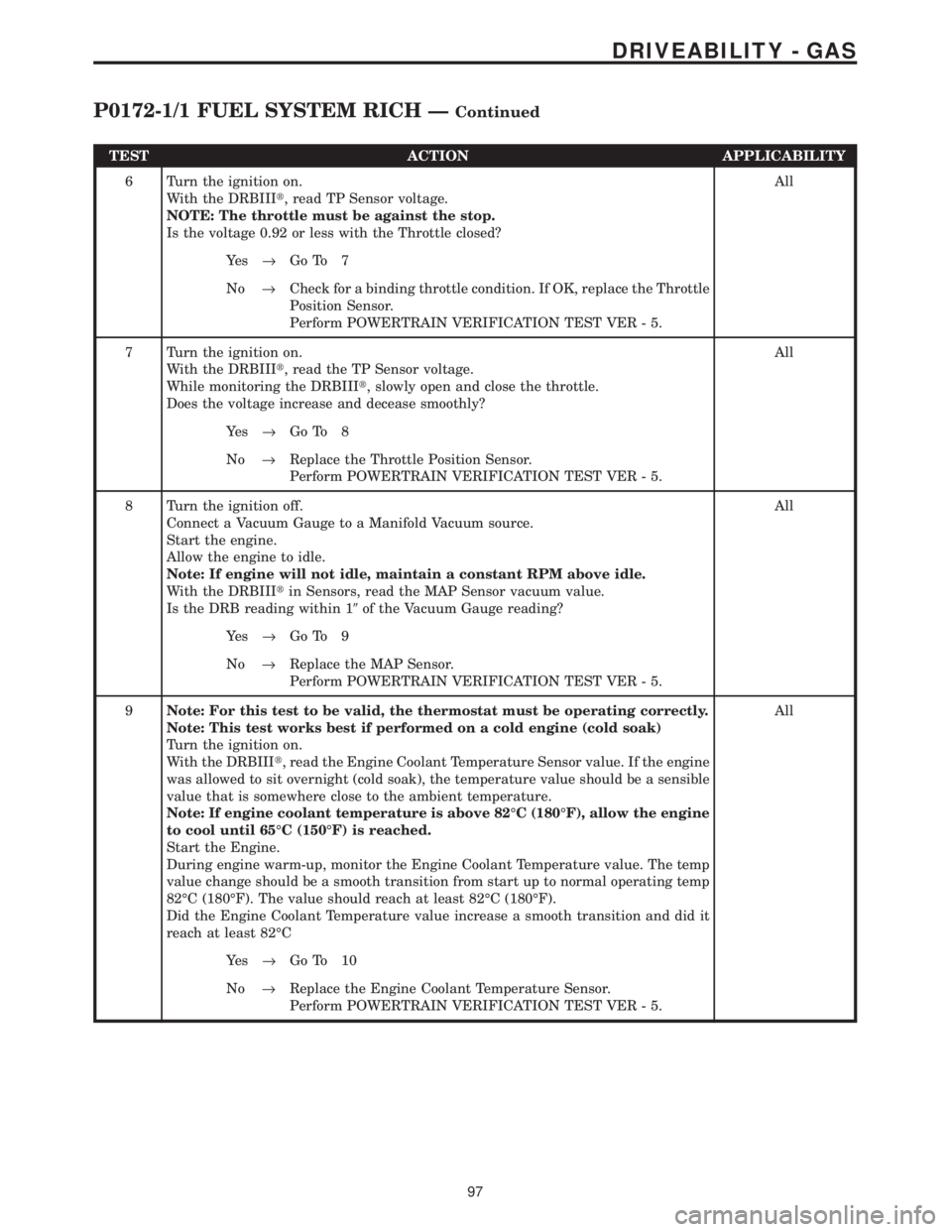
TEST ACTION APPLICABILITY
6 Turn the ignition on.
With the DRBIIIt, read TP Sensor voltage.
NOTE: The throttle must be against the stop.
Is the voltage 0.92 or less with the Throttle closed?All
Ye s®Go To 7
No®Check for a binding throttle condition. If OK, replace the Throttle
Position Sensor.
Perform POWERTRAIN VERIFICATION TEST VER - 5.
7 Turn the ignition on.
With the DRBIIIt, read the TP Sensor voltage.
While monitoring the DRBIIIt, slowly open and close the throttle.
Does the voltage increase and decease smoothly?All
Ye s®Go To 8
No®Replace the Throttle Position Sensor.
Perform POWERTRAIN VERIFICATION TEST VER - 5.
8 Turn the ignition off.
Connect a Vacuum Gauge to a Manifold Vacuum source.
Start the engine.
Allow the engine to idle.
Note: If engine will not idle, maintain a constant RPM above idle.
With the DRBIIItin Sensors, read the MAP Sensor vacuum value.
Is the DRB reading within 19of the Vacuum Gauge reading?All
Ye s®Go To 9
No®Replace the MAP Sensor.
Perform POWERTRAIN VERIFICATION TEST VER - 5.
9Note: For this test to be valid, the thermostat must be operating correctly.
Note: This test works best if performed on a cold engine (cold soak)
Turn the ignition on.
With the DRBIIIt, read the Engine Coolant Temperature Sensor value. If the engine
was allowed to sit overnight (cold soak), the temperature value should be a sensible
value that is somewhere close to the ambient temperature.
Note: If engine coolant temperature is above 82ÉC (180ÉF), allow the engine
to cool until 65ÉC (150ÉF) is reached.
Start the Engine.
During engine warm-up, monitor the Engine Coolant Temperature value. The temp
value change should be a smooth transition from start up to normal operating temp
82ÉC (180ÉF). The value should reach at least 82ÉC (180ÉF).
Did the Engine Coolant Temperature value increase a smooth transition and did it
reach at least 82ÉCAll
Ye s®Go To 10
No®Replace the Engine Coolant Temperature Sensor.
Perform POWERTRAIN VERIFICATION TEST VER - 5.
97
DRIVEABILITY - GAS
P0172-1/1 FUEL SYSTEM RICH ÐContinued
Page 3965 of 4284
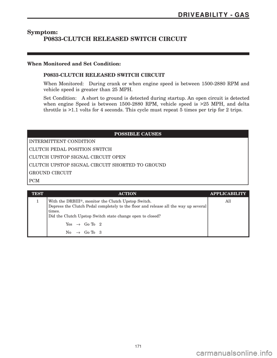
Symptom:
P0833-CLUTCH RELEASED SWITCH CIRCUIT
When Monitored and Set Condition:
P0833-CLUTCH RELEASED SWITCH CIRCUIT
When Monitored: During crank or when engine speed is between 1500-2880 RPM and
vehicle speed is greater than 25 MPH.
Set Condition: A short to ground is detected during startup. An open circuit is detected
when engine Speed is between 1500-2880 RPM, vehicle speed is >25 MPH, and delta
throttle is >1.1 volts for 4 seconds. This cycle must repeat 5 times per trip for 2 trips.
POSSIBLE CAUSES
INTERMITTENT CONDITION
CLUTCH PEDAL POSITION SWITCH
CLUTCH UPSTOP SIGNAL CIRCUIT OPEN
CLUTCH UPSTOP SIGNAL CIRCUIT SHORTED TO GROUND
GROUND CIRCUIT
PCM
TEST ACTION APPLICABILITY
1 With the DRBIIIt, monitor the Clutch Upstop Switch.
Depress the Clutch Pedal completely to the floor and release all the way up several
times.
Did the Clutch Upstop Switch state change open to closed?All
Ye s®Go To 2
No®Go To 3
171
DRIVEABILITY - GAS
Page 3979 of 4284
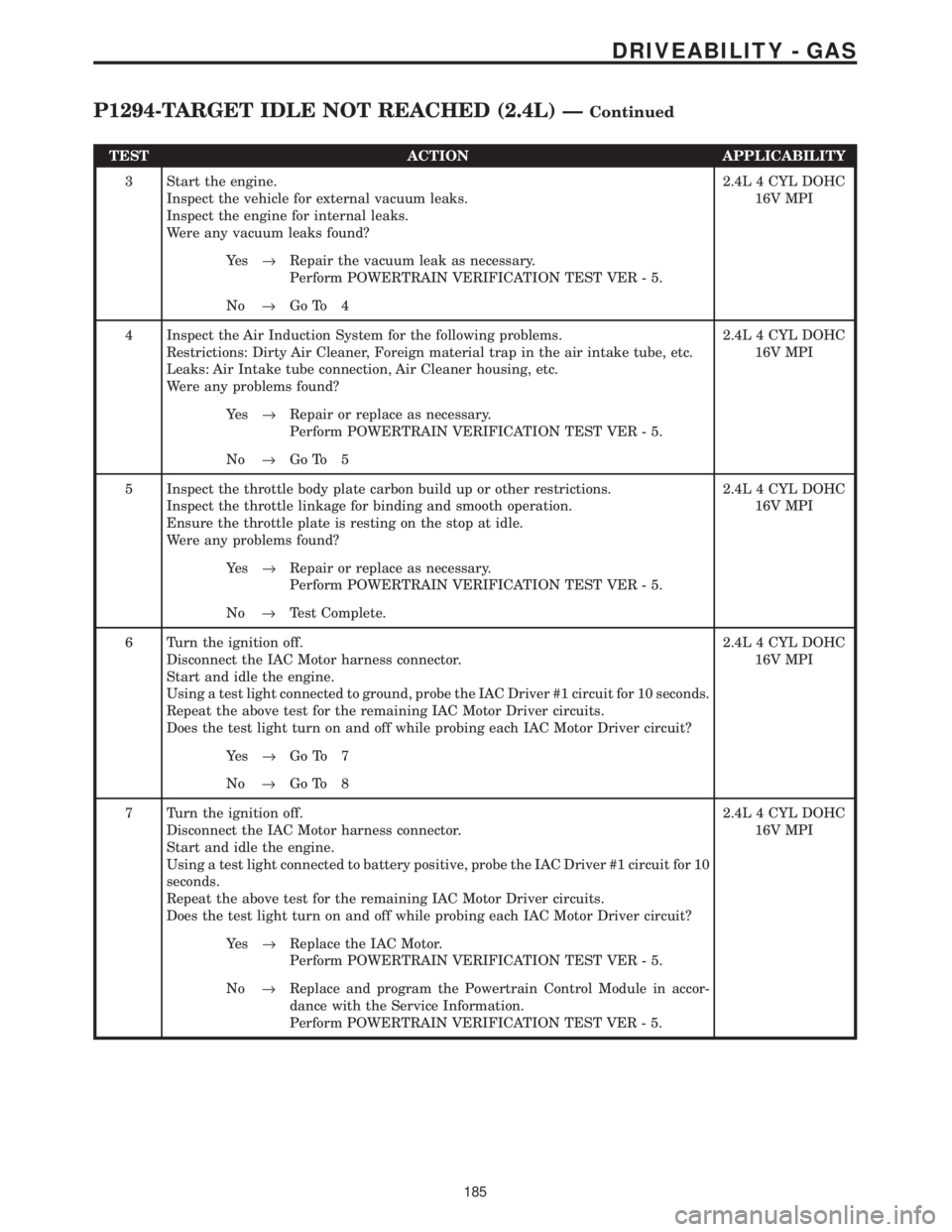
TEST ACTION APPLICABILITY
3 Start the engine.
Inspect the vehicle for external vacuum leaks.
Inspect the engine for internal leaks.
Were any vacuum leaks found?2.4L 4 CYL DOHC
16V MPI
Ye s®Repair the vacuum leak as necessary.
Perform POWERTRAIN VERIFICATION TEST VER - 5.
No®Go To 4
4 Inspect the Air Induction System for the following problems.
Restrictions: Dirty Air Cleaner, Foreign material trap in the air intake tube, etc.
Leaks: Air Intake tube connection, Air Cleaner housing, etc.
Were any problems found?2.4L 4 CYL DOHC
16V MPI
Ye s®Repair or replace as necessary.
Perform POWERTRAIN VERIFICATION TEST VER - 5.
No®Go To 5
5 Inspect the throttle body plate carbon build up or other restrictions.
Inspect the throttle linkage for binding and smooth operation.
Ensure the throttle plate is resting on the stop at idle.
Were any problems found?2.4L 4 CYL DOHC
16V MPI
Ye s®Repair or replace as necessary.
Perform POWERTRAIN VERIFICATION TEST VER - 5.
No®Test Complete.
6 Turn the ignition off.
Disconnect the IAC Motor harness connector.
Start and idle the engine.
Using a test light connected to ground, probe the IAC Driver #1 circuit for 10 seconds.
Repeat the above test for the remaining IAC Motor Driver circuits.
Does the test light turn on and off while probing each IAC Motor Driver circuit?2.4L 4 CYL DOHC
16V MPI
Ye s®Go To 7
No®Go To 8
7 Turn the ignition off.
Disconnect the IAC Motor harness connector.
Start and idle the engine.
Using a test light connected to battery positive, probe the IAC Driver #1 circuit for 10
seconds.
Repeat the above test for the remaining IAC Motor Driver circuits.
Does the test light turn on and off while probing each IAC Motor Driver circuit?2.4L 4 CYL DOHC
16V MPI
Ye s®Replace the IAC Motor.
Perform POWERTRAIN VERIFICATION TEST VER - 5.
No®Replace and program the Powertrain Control Module in accor-
dance with the Service Information.
Perform POWERTRAIN VERIFICATION TEST VER - 5.
185
DRIVEABILITY - GAS
P1294-TARGET IDLE NOT REACHED (2.4L) ÐContinued
Page 3980 of 4284
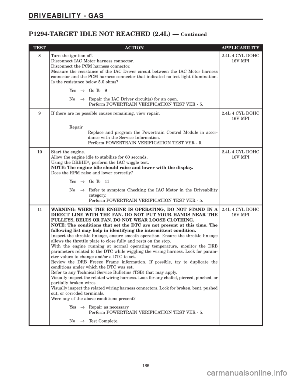
TEST ACTION APPLICABILITY
8 Turn the ignition off.
Disconnect IAC Motor harness connector.
Disconnect the PCM harness connector.
Measure the resistance of the IAC Driver circuit between the IAC Motor harness
connector and the PCM harness connector that indicated no test light illumination.
Is the resistance below 5.0 ohms?2.4L 4 CYL DOHC
16V MPI
Ye s®Go To 9
No®Repair the IAC Driver circuit(s) for an open.
Perform POWERTRAIN VERIFICATION TEST VER - 5.
9 If there are no possible causes remaining, view repair. 2.4L 4 CYL DOHC
16V MPI
Repair
Replace and program the Powertrain Control Module in accor-
dance with the Service Information.
Perform POWERTRAIN VERIFICATION TEST VER - 5.
10 Start the engine.
Allow the engine idle to stabilize for 60 seconds.
Using the DRBIIIt, perform the IAC wiggle test.
NOTE: The engine idle should raise and lower with the display.
Does the RPM raise and lower correctly?2.4L 4 CYL DOHC
16V MPI
Ye s®Go To 11
No®Refer to symptom Checking the IAC Motor in the Driveability
category.
Perform POWERTRAIN VERIFICATION TEST VER - 5.
11WARNING: WHEN THE ENGINE IS OPERATING, DO NOT STAND IN A
DIRECT LINE WITH THE FAN. DO NOT PUT YOUR HANDS NEAR THE
PULLEYS, BELTS OR FAN. DO NOT WEAR LOOSE CLOTHING.
NOTE: The conditions that set the DTC are not present at this time. The
following list may help in identifying the intermittent condition.
Inspect the throttle linkage, ensure smooth operation. Ensure the throttle linkage
allows the throttle plate to close fully and rests on the stop.
With the engine running at normal operating temperature, monitor the DRB
parameters related to the DTC while wiggling the wiring harness. Look for param-
eter values to change and/or a DTC to set.
Review the DRB Freeze Frame information. If possible, try to duplicate the
conditions under which the DTC was set.
Refer to any Technical Service Bulletins (TSB) that may apply.
Visually inspect the related wiring harness. Look for any chafed, pierced, pinched, or
partially broken wires.
Visually inspect the related wiring harness connectors. Look for broken, bent, pushed
out, or corroded terminals.
Were any of the above conditions present?2.4L 4 CYL DOHC
16V MPI
Ye s®Repair as necessary
Perform POWERTRAIN VERIFICATION TEST VER - 5.
No®Test Complete.
186
DRIVEABILITY - GAS
P1294-TARGET IDLE NOT REACHED (2.4L) ÐContinued
Page 3987 of 4284
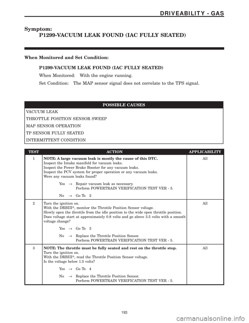
Symptom:
P1299-VACUUM LEAK FOUND (IAC FULLY SEATED)
When Monitored and Set Condition:
P1299-VACUUM LEAK FOUND (IAC FULLY SEATED)
When Monitored: With the engine running.
Set Condition: The MAP sensor signal does not correlate to the TPS signal.
POSSIBLE CAUSES
VACUUM LEAK
THROTTLE POSITION SENSOR SWEEP
MAP SENSOR OPERATION
TP SENSOR FULLY SEATED
INTERMITTENT CONDITION
TEST ACTION APPLICABILITY
1NOTE: A large vacuum leak is mostly the cause of this DTC.
Inspect the Intake manifold for vacuum leaks.
Inspect the Power Brake Booster for any vacuum leaks.
Inspect the PCV system for proper operation or any vacuum leaks.
Were any vacuum leaks found?All
Ye s®Repair vacuum leak as necessary.
Perform POWERTRAIN VERIFICATION TEST VER - 5.
No®Go To 2
2 Turn the ignition on.
With the DRBIIIt, monitor the Throttle Position Sensor voltage.
Slowly open the throttle from the idle position to the wide open throttle position.
Does voltage start at approximately 0.8 volts and go above 3.5 volts with a smooth
voltage change?All
Ye s®Go To 3
No®Replace the Throttle Position Sensor.
Perform POWERTRAIN VERIFICATION TEST VER - 5.
3NOTE: The throttle must be fully seated and rest on the throttle stop.
Turn the ignition on.
With the DRBIIIt, read the Throttle Position Sensor voltage.
Is the voltage below 1.5 volts?All
Ye s®Go To 4
No®Replace the Throttle Position Sensor.
Perform POWERTRAIN VERIFICATION TEST VER - 5.
193
DRIVEABILITY - GAS
Page 4048 of 4284
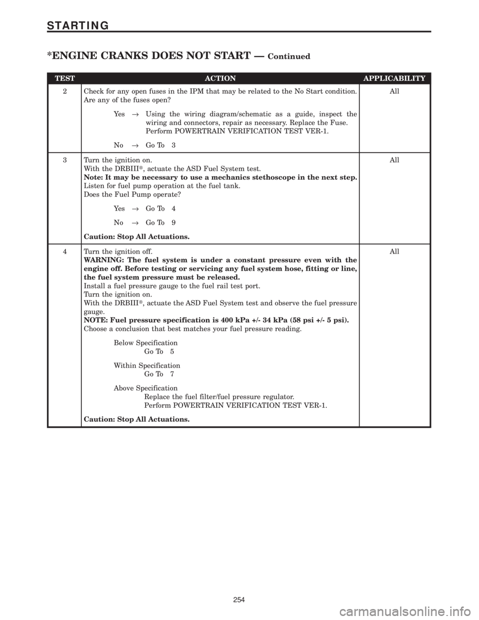
TEST ACTION APPLICABILITY
2 Check for any open fuses in the IPM that may be related to the No Start condition.
Are any of the fuses open?All
Ye s®Using the wiring diagram/schematic as a guide, inspect the
wiring and connectors, repair as necessary. Replace the Fuse.
Perform POWERTRAIN VERIFICATION TEST VER-1.
No®Go To 3
3 Turn the ignition on.
With the DRBIIIt, actuate the ASD Fuel System test.
Note: It may be necessary to use a mechanics stethoscope in the next step.
Listen for fuel pump operation at the fuel tank.
Does the Fuel Pump operate?All
Ye s®Go To 4
No®Go To 9
Caution: Stop All Actuations.
4 Turn the ignition off.
WARNING: The fuel system is under a constant pressure even with the
engine off. Before testing or servicing any fuel system hose, fitting or line,
the fuel system pressure must be released.
Install a fuel pressure gauge to the fuel rail test port.
Turn the ignition on.
With the DRBIIIt, actuate the ASD Fuel System test and observe the fuel pressure
gauge.
NOTE: Fuel pressure specification is 400 kPa +/- 34 kPa (58 psi +/- 5 psi).
Choose a conclusion that best matches your fuel pressure reading.All
Below Specification
Go To 5
Within Specification
Go To 7
Above Specification
Replace the fuel filter/fuel pressure regulator.
Perform POWERTRAIN VERIFICATION TEST VER-1.
Caution: Stop All Actuations.
254
STARTING
*ENGINE CRANKS DOES NOT START ÐContinued
Page 4049 of 4284
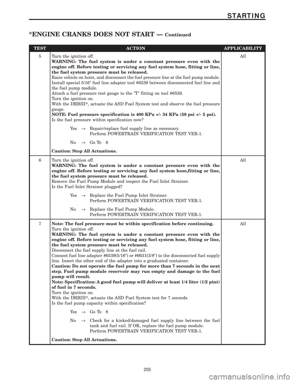
TEST ACTION APPLICABILITY
5 Turn the ignition off.
WARNING: The fuel system is under a constant pressure even with the
engine off. Before testing or servicing any fuel system hose, fitting or line,
the fuel system pressure must be released.
Raise vehicle on hoist, and disconnect the fuel pressure line at the fuel pump module.
Install special 5/169fuel line adapter tool #6539 between disconnected fuel line and
the fuel pump module.
Attach a fuel pressure test gauge to the9T9fitting on tool #6539.
Turn the ignition on.
With the DRBIIIt, actuate the ASD Fuel System test and observe the fuel pressure
gauge.
NOTE: Fuel pressure specification is 400 KPa +/- 34 KPa (58 psi +/- 5 psi).
Is the fuel pressure within specification now?All
Ye s®Repair/replace fuel supply line as necessary.
Perform POWERTRAIN VERIFICATION TEST VER-1.
No®Go To 6
Caution: Stop All Actuations.
6 Turn the ignition off.
WARNING: The fuel system is under a constant pressure even with the
engine off. Before testing or servicing any fuel system hose,fitting or line,
the fuel system pressure must be released.
Remove the Fuel Pump Module and inspect the Fuel Inlet Strainer.
Is the Fuel Inlet Strainer plugged?All
Ye s®Replace the Fuel Pump Inlet Strainer.
Perform POWERTRAIN VERIFICATION TEST VER-1.
No®Replace the Fuel Pump Module.
Perform POWERTRAIN VERIFICATION TEST VER-1.
7Note: The fuel pressure must be within specification before continuing.
Turn the ignition off.
WARNING: The fuel system is under a constant pressure even with the
engine off. Before testing or servicing any fuel system hose, fitting or line,
the fuel system pressure must be released.
Disconnect the fuel supply line at the fuel rail.
Connect fuel line adapter #6539(5/169) or #6631(3/89) to the disconnected fuel supply
line. Insert the other end of the adapter into a graduated container.
Caution: Do not operate the fuel pump for more than 7 seconds in the next
step. Fuel pump module reservoir may run empty and damage to the fuel
pump will result.
Note: Specification: A good fuel pump will deliver at least 1/4 liter (1/2 pint)
of fuel in 7 seconds.
Turn the ignition on.
With the DRBIIIt, actuate the ASD Fuel System test for 7 seconds.
Is the fuel pump capacity within specification?All
Ye s®Go To 8
No®Check for a kinked/damaged fuel supply line between the fuel
tank and fuel rail. If OK, replace the fuel pump module.
Perform POWERTRAIN VERIFICATION TEST VER-1.
Caution: Stop All Actuations.
255
STARTING
*ENGINE CRANKS DOES NOT START ÐContinued
Page 4050 of 4284

TEST ACTION APPLICABILITY
8 The following items need to be checked as a possible cause for a no start condition.
Refer to any Technical Service Bulletins that may apply to the symptom.
The spark plugs must be free from fuel, oil, coolant and/or any foreign material or
deposits.
The fuel must be free from contamination.
The exhaust may be free from restrictions.
The engine compression must be within specifications.
The engine valve timing must be within specifications.
The engine must be free from vacuum leaks.
Were any of the above conditions found?All
Ye s®Repair as necessary.
Perform POWERTRAIN VERIFICATION TEST VER-1.
No®Test Complete.
9 Turn the ignition off.
Disconnect the fuel pump module harness connector.
Turn the ignition on.
With the DRBIIIt, actuate the ASD Fuel System test.
Using a 12 volt test light connected to ground, probe the Fuel Pump Relay Output
circuit at the Fuel Pump Module harness connector.
Does the test light illuminate brightly?All
Ye s®Go To 10
No®Go To 12
Caution: Stop All Actuations.
10 Turn the ignition off.
Disconnect the Fuel Pump Module harness connector.
Note: Check connectors - It is critical that the connector is free from any
signs of corrosion or deformities - Clean/repair as necessary.
Using a test light connected to battery voltage, probe the Fuel Pump ground circuit
at the Fuel Pump Module harness connector.
Does the test light illuminate brightly?All
Ye s®Go To 11
No®Repair the open/high resistance in the fuel pump ground circuit.
Perform POWERTRAIN VERIFICATION TEST VER-1.
11 If there are no possible causes remaining, view repair. All
Repair
Replace the Fuel Pump Module.
Perform POWERTRAIN VERIFICATION TEST VER-1.
12 Turn the ignition off.
Remove the Fuel Pump Relay from the IPM.
With a 12 volt test light connected to ground, probe the Fuel Pump Relay Fused B+
circuit in the IPM.
Does the test light illuminate?All
Ye s®Go To 13
No®Check for an open Fuel Pump fuse, repair cause of open. If OK,
replace the IPM Fuse & Relay Center.
Perform POWERTRAIN VERIFICATION TEST VER-1.
256
STARTING
*ENGINE CRANKS DOES NOT START ÐContinued