2001 CHRYSLER VOYAGER stop start
[x] Cancel search: stop startPage 1552 of 4284
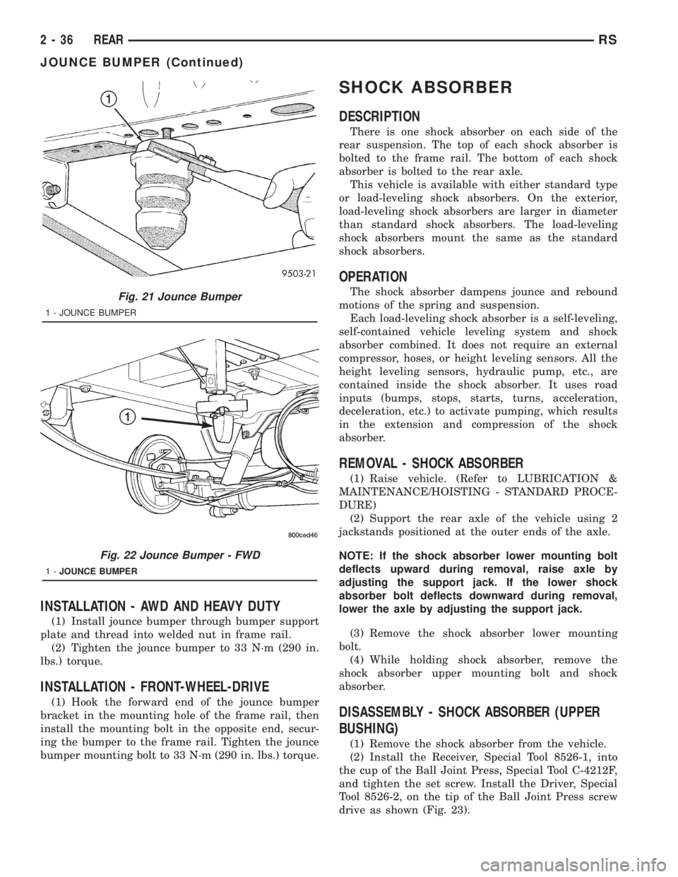
INSTALLATION - AWD AND HEAVY DUTY
(1) Install jounce bumper through bumper support
plate and thread into welded nut in frame rail.
(2) Tighten the jounce bumper to 33 N´m (290 in.
lbs.) torque.
INSTALLATION - FRONT-WHEEL-DRIVE
(1) Hook the forward end of the jounce bumper
bracket in the mounting hole of the frame rail, then
install the mounting bolt in the opposite end, secur-
ing the bumper to the frame rail. Tighten the jounce
bumper mounting bolt to 33 N´m (290 in. lbs.) torque.
SHOCK ABSORBER
DESCRIPTION
There is one shock absorber on each side of the
rear suspension. The top of each shock absorber is
bolted to the frame rail. The bottom of each shock
absorber is bolted to the rear axle.
This vehicle is available with either standard type
or load-leveling shock absorbers. On the exterior,
load-leveling shock absorbers are larger in diameter
than standard shock absorbers. The load-leveling
shock absorbers mount the same as the standard
shock absorbers.
OPERATION
The shock absorber dampens jounce and rebound
motions of the spring and suspension.
Each load-leveling shock absorber is a self-leveling,
self-contained vehicle leveling system and shock
absorber combined. It does not require an external
compressor, hoses, or height leveling sensors. All the
height leveling sensors, hydraulic pump, etc., are
contained inside the shock absorber. It uses road
inputs (bumps, stops, starts, turns, acceleration,
deceleration, etc.) to activate pumping, which results
in the extension and compression of the shock
absorber.
REMOVAL - SHOCK ABSORBER
(1) Raise vehicle. (Refer to LUBRICATION &
MAINTENANCE/HOISTING - STANDARD PROCE-
DURE)
(2) Support the rear axle of the vehicle using 2
jackstands positioned at the outer ends of the axle.
NOTE: If the shock absorber lower mounting bolt
deflects upward during removal, raise axle by
adjusting the support jack. If the lower shock
absorber bolt deflects downward during removal,
lower the axle by adjusting the support jack.
(3) Remove the shock absorber lower mounting
bolt.
(4) While holding shock absorber, remove the
shock absorber upper mounting bolt and shock
absorber.
DISASSEMBLY - SHOCK ABSORBER (UPPER
BUSHING)
(1) Remove the shock absorber from the vehicle.
(2) Install the Receiver, Special Tool 8526-1, into
the cup of the Ball Joint Press, Special Tool C-4212F,
and tighten the set screw. Install the Driver, Special
Tool 8526-2, on the tip of the Ball Joint Press screw
drive as shown (Fig. 23).
Fig. 21 Jounce Bumper
1 - JOUNCE BUMPER
Fig. 22 Jounce Bumper - FWD
1-JOUNCE BUMPER
2 - 36 REARRS
JOUNCE BUMPER (Continued)
Page 1641 of 4284
shoes on the opposite side of the vehicle as well as
the shoes failing inspection.
If the brake shoe assemblies do not require
replacement, be sure to reinstall the brake shoes in
the original position they were remove from.
INSTALLATION - FRONT DISC BRAKE SHOES
(DISC/DISC BRAKES)
(1) Begin on one side of the vehicle or the other.
(2) Completely retract the caliper piston back into
its bore in the brake caliper (This is required for cal-
iper installation on the brake rotor with new brake
shoes installed).
(3) If applied, remove the protective paper from
the noise suppression gasket on the rear of both the
inner and outer brake shoe assemblies.
(4) Install the new inboard brake shoe into the cal-
iper piston by firmly pressing its retaining clip into
the piston bore. Be sure the inboard brake shoe is
positioned squarely against the face of the caliper
piston.
(5) Lubricate both adapter abutments where the
shoes slide with a small amount of MopartMultipur-
pose Lubricant, or equivalent.
(6) Slide the new outboard brake shoe into the cal-
iper adapter up against the outside of the brake
rotor.
CAUTION: Use care when installing the caliper
assembly onto the steering knuckle, so the caliper
guide pin bushings do not get damaged by the
steering knuckle bosses.
(7) Carefully position the brake caliper over the
brake rotor and adapter.
(8) Install the caliper guide pin bolts and tighten
to a torque of 35 N´m (26 ft. lbs.).Extreme caution
should be taken not to cross thread the caliper
guide pin bolts.
(9) Install the anti-rattle clip on the outboard side
of the caliper. Start the clip into the holes on the cal-
iper, then stretch the clip legs past the abutments on
the caliper adapter.
(10) Install the wheel and tire assembly. Tighten
the wheel mounting nuts in proper sequence until all
nuts are torqued to half specification, then repeat the
tightening sequence to the full specified torque of 135
N´m (100 ft. lbs.).
(11) Repeat the above procedure on other side of
the vehicle.
(12) Lower vehicle.
(13) Pump the brake pedal several times. This will
set the shoes to the brake rotor.
(14) Check and adjust brake fluid level as neces-
sary.(15) Road test the vehicle and make several stops
to wear off any foreign material on the brakes and to
seat the brake shoes.
INSTALLATION - FRONT DISC BRAKE SHOES
(DISC/DRUM BRAKES)
NOTE: Perform steps Step 1 through Step 5on each
side of the vehicle.
(1) Place the brake shoes in the adapter anti-rattle
clips.
(2) Completely retract the caliper piston back into
the bore of the caliper.
CAUTION: Use care when installing the caliper onto
the disc brake adapter to avoid damaging the boots
on the caliper guide pins.
(3) Install the disc brake caliper over the brake
shoes on the brake caliper adapter.
(4) Align the caliper guide pin bolt holes with the
guide pins. Install the caliper guide pin bolts and
tighten them to a torque of 35 N´m (26 ft. lbs.) (Fig.
14).
(5) Install the tire and wheel assembly. Tighten
the wheel mounting nuts to a torque of 135 N´m (100
ft. lbs.).
(6) Lower the vehicle.
(7) Pump the brake pedal several times. This will
set the shoes to the brake rotor.
(8) Check and adjust the brake fluid level as nec-
essary.
(9) Road test the vehicle and make several stops to
wear off any foreign material on the brakes and to
seat the brake shoes.
BRAKE PADS/SHOES - REAR
DISC
REMOVAL - REAR DISC BRAKE SHOES
(1) Raise vehicle on jackstands or centered on a
hoist. (Refer to LUBRICATION & MAINTENANCE/
HOISTING - STANDARD PROCEDURE).
(2) Remove rear wheel and tire assemblies from
vehicle.
(3) Remove the caliper to adapter guide pin bolts
(Fig. 15).
(4) Remove rear caliper from adapter using the fol-
lowing procedure. First rotate rear of caliper up from
the adapter. Then pull the front of the caliper and
the outboard brake shoe anti-rattle clip out from
under the front abutment on the adapter (Fig. 16).
RSBRAKES - BASE5-15
BRAKE PADS/SHOES - FRONT (Continued)
Page 1651 of 4284
(7) Reinstall the caliper on the vehicle and bleed
the brakes as necessary. Refer to Installation in this
section.
INSTALLATION - FRONT DISC BRAKE CALIPER
(DISC/DISC BRAKES)
CAUTION: TRW and Continental Teves brake cali-
pers are not interchangeable. Each caliper is specif-
ically designed for the unique brake system (TRW -
disc/drum brake combination and Continental Teves
- disc/disc brake combination). If calipers are inter-
changed, improper performance, noise and
increased stopping distance can occur.
(1) Completely retract the caliper piston back into
piston bore of the caliper. Use a C-clamp to retract
the piston if necessary. Place a wood block over the
piston before installing the C-clamp to avoid damag-
ing the piston.
CAUTION: Use care when installing the brake cali-
per assembly onto the steering knuckle, so that the
seals on the caliper guide pin bushings do not get
damaged by the steering knuckle bosses.
(2) Carefully position the brake caliper and shoes
over the brake rotor and adapter.
(3) Install the caliper guide pin bolts and tighten
to a torque of 35 N´m (26 ft. lbs.).Extreme caution
should be taken not to cross thread the caliper
guide pin bolts.
(4) Install the anti-rattle clip on the outboard side
of the caliper. Start the clip into the holes on the cal-
iper, then stretch the clip legs past the abutments on
the caliper adapter.
CAUTION: When connecting the brake hose to the
caliper, install new brake hose to caliper special
copper washers.
(5) Install the brake hose on the caliper. To do
this, first place one NEW special fitting washer on
each side of the hose fitting, then slide the banjo bolt
through the fitting. Next, thread the banjo bolt into
the threaded port on the rear of the brake caliper.
Tighten the banjo bolt to a torque of 47 N´m (35 ft.
lbs.).
(6) Install the wheel and tire assembly. Tighten
the wheel mounting stud nuts in proper sequence
until all nuts are torqued to half specification, then
repeat the tightening sequence to the full specified
torque of 135 N´m (100 ft. lbs.).
(7) Lower the vehicle.
(8) Remove the brake pedal depressor (holding)
tool.
(9) Bleed the hydraulic brake circuit to the brake
caliper. (Refer to 5 - BRAKES - STANDARD PROCE-
DURE)
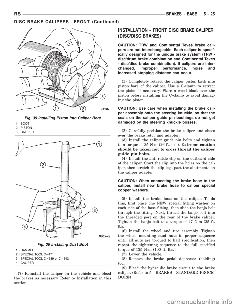
Fig. 35 Installing Piston Into Caliper Bore
1 - BOOT
2 - PISTON
3 - CALIPER
Fig. 36 Installing Dust Boot
1 - HAMMER
2 - SPECIAL TOOL C-4171
3 - SPECIAL TOOL C-4689 or C-4842
4 - CALIPER
RSBRAKES - BASE5-25
DISC BRAKE CALIPERS - FRONT (Continued)
Page 1694 of 4284
tem enters the ABS mode. During ABS braking,
hydraulic pressure in the four wheel circuits is mod-
ulated to prevent any wheel from locking. Each
wheel circuit is designed with a set of electric sole-
noids to allow modulation, although for vehicle sta-
bility, both rear wheel solenoids receive the same
electrical signal. Wheel lockup may be perceived at
the very end of an ABS stop and is considered nor-
mal.
During an ABS stop, the brakes hydraulic system
is still diagonally split. However, the brake system
pressure is further split into three control channels.
During antilock operation of the vehicle's brake sys-
tem, the front wheels are controlled independently
and are on two separate control channels, and the
rear wheels of the vehicle are controlled together.
The system can build and release pressure at each
wheel, depending on signals generated by the wheel
speed sensors (WSS) at each wheel and received at
the controller antilock brake (CAB).
NOISE AND BRAKE PEDAL FEEL
During ABS braking, some brake pedal movement
may be felt. In addition, ABS braking will create
ticking, popping, or groaning noises heard by the
driver. This is normal and is due to pressurized fluid
being transferred between the master cylinder and
the brakes. If ABS operation occurs during hard
braking, some pulsation may be felt in the vehicle
body due to fore and aft movement of the suspension
as brake pressures are modulated.
At the end of an ABS stop, ABS is turned off when
the vehicle is slowed to a speed of 3±4 mph. There
may be a slight brake pedal drop anytime that the
ABS is deactivated, such as at the end of the stop
when the vehicle speed is less than 3 mph or during
an ABS stop where ABS is no longer required. These
conditions exist when a vehicle is being stopped on a
road surface with patches of ice, loose gravel, or sand
on it. Also, stopping a vehicle on a bumpy road sur-
face activates ABS because of the wheel hop caused
by the bumps.
TIRE NOISE AND MARKS
Although the ABS system prevents complete wheel
lockup, some wheel slip is desired in order to achieve
optimum braking performance. Wheel slip is defined
as follows: 0 percent slip means the wheel is rolling
freely and 100 percent slip means the wheel is fully
locked. During brake pressure modulation, wheel slip
is allowed to reach up to 25±30 percent. This means
that the wheel rolling velocity is 25±30 percent less
than that of a free rolling wheel at a given vehicle
speed. This slip may result in some tire chirping,
depending on the road surface. This sound should not
be interpreted as total wheel lockup.Complete wheel lockup normally leaves black tire
marks on dry pavement. The ABS will not leave dark
black tire marks since the wheel never reaches a
fully locked condition. However, tire marks may be
noticeable as light patched marks.
START-UP CYCLE
When the ignition is turned on, a popping sound
and a slight brake pedal movement may be noticed.
The ABS warning lamp will also be on for up to 5
seconds after the ignition is turned on. When the
vehicle is first driven off, a humming may be heard
or felt by the driver at approximately 20±40 kph
(12±25 mph). All of these conditions are a normal
function of ABS as the system is performing a diag-
nosis check.
PREMATURE ABS CYCLING
Symptoms of premature ABS cycling include: click-
ing sounds from the solenoid valves; pump/motor
running; and pulsations in the brake pedal. Prema-
ture ABS cycling can occur at any braking rate of the
vehicle and on any type of road surface. Neither the
red BRAKE warning lamp, nor the amber ABS warn-
ing lamp, illuminate and no fault codes are stored in
the CAB.
Premature ABS cycling is a condition that needs to
be correctly assessed when diagnosing problems with
the antilock brake system. It may be necessary to use
a DRB scan tool to detect and verify premature ABS
cycling.
Check the following common causes when diagnos-
ing premature ABS cycling: damaged tone wheels;
incorrect tone wheels; damaged steering knuckle
wheel speed sensor mounting bosses; loose wheel
speed sensor mounting bolts; excessive tone wheel
runout; or an excessively large tone wheel-to-wheel
speed sensor air gap. Give special attention to these
components when diagnosing a vehicle exhibiting
premature ABS cycling.
After diagnosing the defective component, repair or
replace it as required. When the component repair or
replacement is completed, test drive the vehicle to
verify that premature ABS cycling has been cor-
rected.
OPERATION - ELECTRONIC BRAKE
DISTRIBUTION
Upon entry into EBD the inlet valve for the rear
brake circuit is switched on so that the fluid supply
from the master cylinder is shut off. In order to
decrease the rear brake pressure, the outlet valve for
the rear brake circuit is pulsed. This allows fluid to
enter the low pressure accumulator (LPA) in the
hydraulic control unit (HCU) resulting in a drop in
fluid pressure to the rear brakes. In order to increase
5 - 68 BRAKES - ABSRS
BRAKES - ABS (Continued)
Page 1751 of 4284
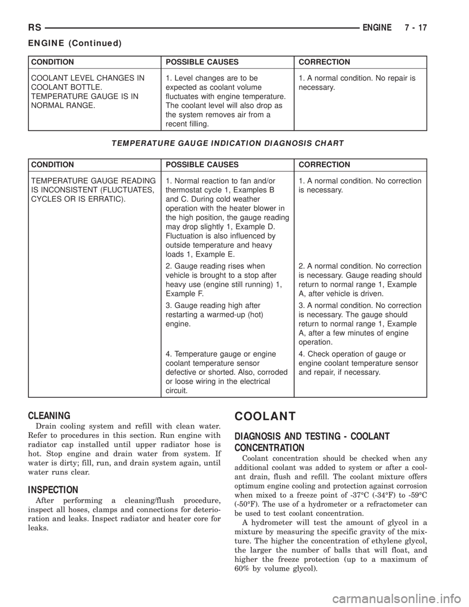
CONDITION POSSIBLE CAUSES CORRECTION
COOLANT LEVEL CHANGES IN
COOLANT BOTTLE.
TEMPERATURE GAUGE IS IN
NORMAL RANGE.1. Level changes are to be
expected as coolant volume
fluctuates with engine temperature.
The coolant level will also drop as
the system removes air from a
recent filling.1. A normal condition. No repair is
necessary.
TEMPERATURE GAUGE INDICATION DIAGNOSIS CHART
CONDITION POSSIBLE CAUSES CORRECTION
TEMPERATURE GAUGE READING
IS INCONSISTENT (FLUCTUATES,
CYCLES OR IS ERRATIC).1. Normal reaction to fan and/or
thermostat cycle 1, Examples B
and C. During cold weather
operation with the heater blower in
the high position, the gauge reading
may drop slightly 1, Example D.
Fluctuation is also influenced by
outside temperature and heavy
loads 1, Example E.1. A normal condition. No correction
is necessary.
2. Gauge reading rises when
vehicle is brought to a stop after
heavy use (engine still running) 1,
Example F.2. A normal condition. No correction
is necessary. Gauge reading should
return to normal range 1, Example
A, after vehicle is driven.
3. Gauge reading high after
restarting a warmed-up (hot)
engine.3. A normal condition. No correction
is necessary. The gauge should
return to normal range 1, Example
A, after a few minutes of engine
operation.
4. Temperature gauge or engine
coolant temperature sensor
defective or shorted. Also, corroded
or loose wiring in the electrical
circuit.4. Check operation of gauge or
engine coolant temperature sensor
and repair, if necessary.
CLEANING
Drain cooling system and refill with clean water.
Refer to procedures in this section. Run engine with
radiator cap installed until upper radiator hose is
hot. Stop engine and drain water from system. If
water is dirty; fill, run, and drain system again, until
water runs clear.
INSPECTION
After performing a cleaning/flush procedure,
inspect all hoses, clamps and connections for deterio-
ration and leaks. Inspect radiator and heater core for
leaks.
COOLANT
DIAGNOSIS AND TESTING - COOLANT
CONCENTRATION
Coolant concentration should be checked when any
additional coolant was added to system or after a cool-
ant drain, flush and refill. The coolant mixture offers
optimum engine cooling and protection against corrosion
when mixed to a freeze point of -37ÉC (-34ÉF) to -59ÉC
(-50ÉF). The use of a hydrometer or a refractometer can
be used to test coolant concentration.
A hydrometer will test the amount of glycol in a
mixture by measuring the specific gravity of the mix-
ture. The higher the concentration of ethylene glycol,
the larger the number of balls that will float, and
higher the freeze protection (up to a maximum of
60% by volume glycol).
RSENGINE7-17
ENGINE (Continued)
Page 1777 of 4284
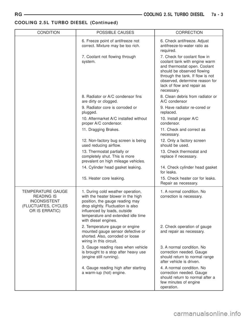
CONDITION POSSIBLE CAUSES CORRECTION
6. Freeze point of antifreeze not
correct. Mixture may be too rich.6. Check antifreeze. Adjust
antifreeze-to-water ratio as
required.
7. Coolant not flowing through
system.7. Check for coolant flow in
coolant tank with engine warm
and thermostat open. Coolant
should be observed flowing
through the tank. If flow is not
observed, determine reason for
lack of flow and repair as
necessary.
8. Radiator or A/C condensor fins
are dirty or clogged.8. Clean debris from radiator or
A/C condensor
9. Radiator core is corroded or
plugged.9. Have radiator re-cored or
replaced.
10. Aftermarket A/C installed without
proper A/C condensor.10. Install proper A/C
condensor.
11. Dragging Brakes. 11. Check and correct as
necessary.
12. Non-factory bug screen is being
used reducing airflow.12. Only a factory screen
should be used.
13. Thermostat partially or
completely shut. This is more
prevalent on high mileage vehicles.13. Check thermostat and
replace if necessary.
14. Cylinder head gasket leaking. 14. Check cylinder head gasket
for leaks.
15. Heater core leaking. 15. Check heater cor for leaks.
Repair as necessary.
TEMPERATURE GAUGE
READING IS
INCONSISTENT
(FLUCTUATES, CYCLES
OR IS ERRATIC)1. During cold weather operation,
with the heater blower in the high
position, the gauge reading may
drop slightly. Fluctuation is also
influenced by loads, outside
temperature and extended idle time
with diesel engines.1. A normal condition. No
correction is necessary.
2. Temperature gauge or engine
mounted gauge sensor defective or
shorted. Also, corroded or loose
wiring in this circuit.2. Check operation of gauge
and repair as necessary.
3. Gauge reading rises when vehicle
is brought to a stop after heavy use
(engine still running).3. A normal condition. No
correction needed. Gauge
should return to normal range
after vehicle is driven.
4. Gauge reading high after starting
a warm-iup (hot) engine.4. A normal condition. No
correction needed. Gauge
should return to normal after a
few minutes of engine
operation.
RGCOOLING 2.5L TURBO DIESEL7a-3
COOLING 2.5L TURBO DIESEL (Continued)
Page 1821 of 4284
²Engine running at 420 to 480 rpm for 10 sec-
onds
²Oil pressure switch closed to ground for (1 sec-
ond minimum, 2 seconds maximum)
Chime rate: 168 to 192 chimes per minute.
DIAGNOSIS AND TESTING - SEAT BELT CHIME
The seat belt chime will sound for 4 to 8 seconds,
when the ignition is turned on and the driver's seat
belt is not buckled (seat belt switch is closed to
ground). This is a reminder to the driver to buckle
the seat belt. The seat belt lamp is controlled by the
ORC. The cluster will also bulb check the seat belt
warning lamp for 6 seconds. Buckling the driver's
seat belt before the time out has expired will cause
the chime to stop immediately. Chime rate: 38 to 62
chimes per minute but the lamp will remain on until
6 seconds have expired.
To test the seat belt warning system, the ignition
switch must be in the OFF position for 1 minute
before starting the test. Turn the ignition switch to
the on position with the driver's seat belt not buck-
led. The seat belt warning lamp should light and the
chime should sound 4 to 8 seconds.
DIAGNOSIS AND TESTING - SEAT BELT LAMP
The seat belt lamp in the instrument cluster sig-
nals the vehicle passengers to fasten their seat belts.
The seat belt lamp is illuminated directly by the
instrument cluster for 6 seconds after the instrument
cluster receives the message from the ORC. The seat
belt lamp is therefore illuminated for 6 seconds
whenever the ignition switch is moved to run/start
position.
(1) While ignition is off, the seat belt lamp will not
be illuminated.
(2) The ignition power feed status will be updated
every 250 milliseconds or on change.
(3) This lamp will be checked by the instrument
cluster for 6 seconds with every run/start cycle of the
ignition switch.
DIAGNOSIS AND TESTING - TURN SIGNAL ON
CHIME
The turn signal on chime will warn the driver that
the turn signals have been left on. When the body
control module receives a turn signal input for 1/4.0
mile, vehicle speed is greater than 24 km/h (15 mph),
the chime will sound continuously until the turn sig-nal is turned OFF. If vehicle speed drops below 24
km/h (15 mph) prior to the warning being activated,
the accumulated distance traveled will be reset. The
turn signal chime is not activated when the emer-
gency flashers are turned on. Chime rate: 50612
chimes per minute.
For the turn signal warning system to operate:
²Must have input from either the right or left
turn signal lamps. Creates a voltage change between
0 and battery voltage.
²The vehicle speed sensor sends a message to the
Powertrain Control Module that vehicle has exceeded
24 km/h (15 mph) for 1/4.0 mile).
²When the above two conditions are met, the
chime will sound. The chime will stop when no fur-
ther voltage change is detected.
²If hazard warning signals are pulsing, no chime
will sound.
²If speed drops below 24 km/h (15 mph) before
the warning is issued, the warning will not be issued
and the distance counter will be reset.
²If turn signal lamps are not working properly,
the chime will not sound.
²When using the scan tool, refer to the proper
Body Diagnostic Manual for the procedure.
DIAGNOSIS AND TESTING - WARNING LAMP
ANNOUNCEMENT CHIME
The warning lamp announcement chime will warn
the driver to scan the instrument cluster to observe
which warning lamp is illuminated. Whenever the
volts, low fuel, airbag, door ajar or gate ajar lamps
are first illuminated, the chime will sound one tone.
The door/liftgate ajar warning lamp announcement
chime sounds only if the vehicle speed is above 4
m.p.h.
Two seconds after ignition switch is turned ON or
until the seat belt warning chime ends, all warning
announcement chimes will be consolidated into one
warning announcement. This will occur 2 seconds
after the seat belt warning chime ends. If a warning
announcement should occur while another warning
chime in progress (turn signal, low oil pressure or
high speed warnings), no additional chimes will
sound after the chime in progress ends. All associ-
ated lamps will be illuminated, and the active chime
will be the warning announcement.
RSCHIME/BUZZER8B-3
CHIME/BUZZER (Continued)
Page 1830 of 4284
²Front Fog Lamp Relay Actuation
²Front and Rear Blower Motor Relay Actuation
²Accessory Relay Actuation
²Electronic Back Light (EBL) Rear Defogger
²Horn Relay Actuation
²Park Lamp Relay Actuation
²Name Brand Speaker (NBS) Relay Actuation
²Headlamp Washer Relay Actuation
²Diesel Cabin Heater (Diesel Engine Vehicles)
The following inputs areReceived/Monitoredby
the Front Control Module:
²B+ Connection Detection
²Ambient Temperature Sensing
²Right/Left Park Lamp Outage
²Ignition Switch Start Only
²Ignition Switch Run and Start Only
²Washer Fluid Level
²Windshield Wiper Park
²Brake Fluid Level
²Back-Up switch
²Stop Lamp Sense
²Engine Crank Signal (Diesel Engine Vehicles)
²Horn Input
DIAGNOSIS AND TESTING - FRONT CONTROL
MODULE
The front control module is a printed circuit board
based module with a on-board micro-processor. The
front control module interfaces with other electronic
modules in the vehicle via the Programmable Com-
munications Interface (PCI) data bus (J1850). In
order to obtain conclusive testing the Programmable
Communications Interface (PCI) data bus network
and all of the electronic modules that provide inputs
to, or receive outputs from the front control module
must be checked. All PCI (J1850) communication
faults must be resolved prior to further diagnosing
any front control module related issues.
The front control module was designed to be diag-
nosed with an appropriate diagnostic scan tool, such
as the DRB IIIt. The most reliable, efficient, and
accurate means to diagnose the front control module
requires the use of a DRB IIItscan tool and the
proper Body Diagnostic Procedures manual.
Before any testing of the front control module is
attempted, the battery should be fully charged and
all wire harness and ground connections inspected
around the affected areas on the vehicle.
REMOVAL
(1) Disconnect the positive and negative battery
cables from the battery.
(2) Remove the battery from the vehicle. Refer to
the procedure in Battery Systems.(3) Using a long flat-pladed screwdriver, gently
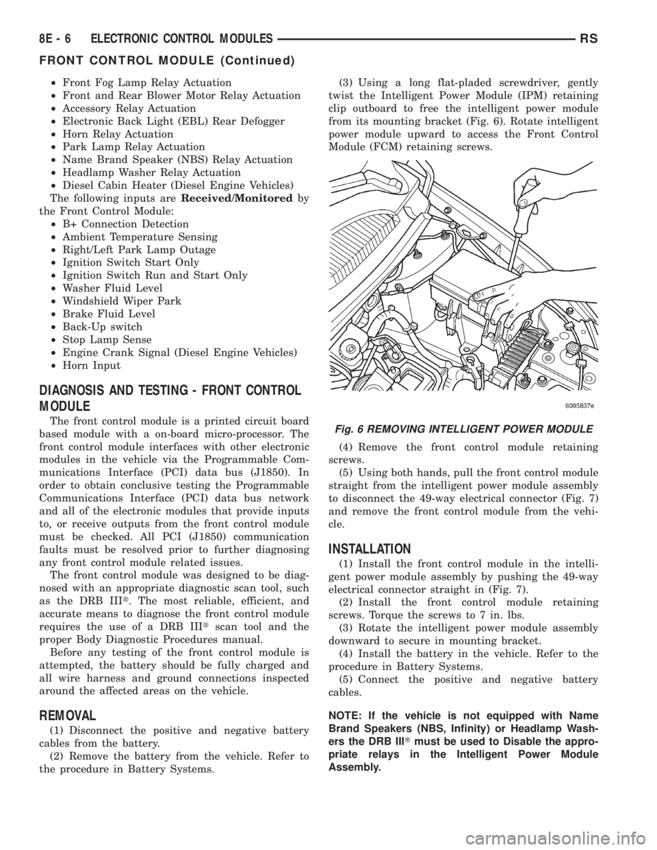
twist the Intelligent Power Module (IPM) retaining
clip outboard to free the intelligent power module
from its mounting bracket (Fig. 6). Rotate intelligent
power module upward to access the Front Control
Module (FCM) retaining screws.
(4) Remove the front control module retaining
screws.
(5) Using both hands, pull the front control module
straight from the intelligent power module assembly
to disconnect the 49-way electrical connector (Fig. 7)
and remove the front control module from the vehi-
cle.
INSTALLATION
(1) Install the front control module in the intelli-
gent power module assembly by pushing the 49-way
electrical connector straight in (Fig. 7).
(2) Install the front control module retaining
screws. Torque the screws to 7 in. lbs.
(3) Rotate the intelligent power module assembly
downward to secure in mounting bracket.
(4) Install the battery in the vehicle. Refer to the
procedure in Battery Systems.
(5) Connect the positive and negative battery
cables.
NOTE: If the vehicle is not equipped with Name
Brand Speakers (NBS, Infinity) or Headlamp Wash-
ers the DRB IIITmust be used to Disable the appro-
priate relays in the Intelligent Power Module
Assembly.
Fig. 6 REMOVING INTELLIGENT POWER MODULE
8E - 6 ELECTRONIC CONTROL MODULESRS
FRONT CONTROL MODULE (Continued)