2001 CHRYSLER VOYAGER stop start
[x] Cancel search: stop startPage 1224 of 4284
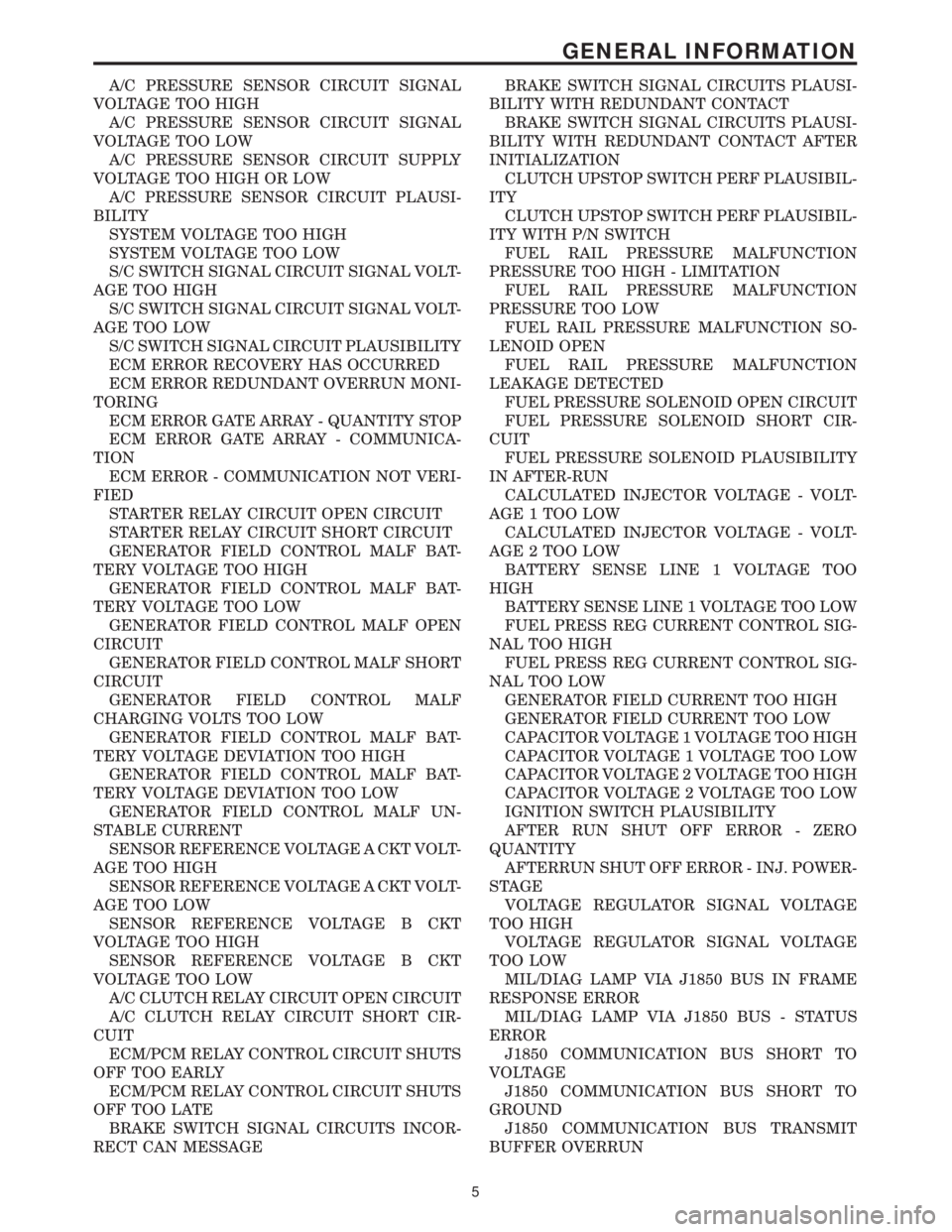
A/C PRESSURE SENSOR CIRCUIT SIGNAL
VOLTAGE TOO HIGH
A/C PRESSURE SENSOR CIRCUIT SIGNAL
VOLTAGE TOO LOW
A/C PRESSURE SENSOR CIRCUIT SUPPLY
VOLTAGE TOO HIGH OR LOW
A/C PRESSURE SENSOR CIRCUIT PLAUSI-
BILITY
SYSTEM VOLTAGE TOO HIGH
SYSTEM VOLTAGE TOO LOW
S/C SWITCH SIGNAL CIRCUIT SIGNAL VOLT-
AGE TOO HIGH
S/C SWITCH SIGNAL CIRCUIT SIGNAL VOLT-
AGE TOO LOW
S/C SWITCH SIGNAL CIRCUIT PLAUSIBILITY
ECM ERROR RECOVERY HAS OCCURRED
ECM ERROR REDUNDANT OVERRUN MONI-
TORING
ECM ERROR GATE ARRAY - QUANTITY STOP
ECM ERROR GATE ARRAY - COMMUNICA-
TION
ECM ERROR - COMMUNICATION NOT VERI-
FIED
STARTER RELAY CIRCUIT OPEN CIRCUIT
STARTER RELAY CIRCUIT SHORT CIRCUIT
GENERATOR FIELD CONTROL MALF BAT-
TERY VOLTAGE TOO HIGH
GENERATOR FIELD CONTROL MALF BAT-
TERY VOLTAGE TOO LOW
GENERATOR FIELD CONTROL MALF OPEN
CIRCUIT
GENERATOR FIELD CONTROL MALF SHORT
CIRCUIT
GENERATOR FIELD CONTROL MALF
CHARGING VOLTS TOO LOW
GENERATOR FIELD CONTROL MALF BAT-
TERY VOLTAGE DEVIATION TOO HIGH
GENERATOR FIELD CONTROL MALF BAT-
TERY VOLTAGE DEVIATION TOO LOW
GENERATOR FIELD CONTROL MALF UN-
STABLE CURRENT
SENSOR REFERENCE VOLTAGE A CKT VOLT-
AGE TOO HIGH
SENSOR REFERENCE VOLTAGE A CKT VOLT-
AGE TOO LOW
SENSOR REFERENCE VOLTAGE B CKT
VOLTAGE TOO HIGH
SENSOR REFERENCE VOLTAGE B CKT
VOLTAGE TOO LOW
A/C CLUTCH RELAY CIRCUIT OPEN CIRCUIT
A/C CLUTCH RELAY CIRCUIT SHORT CIR-
CUIT
ECM/PCM RELAY CONTROL CIRCUIT SHUTS
OFF TOO EARLY
ECM/PCM RELAY CONTROL CIRCUIT SHUTS
OFF TOO LATE
BRAKE SWITCH SIGNAL CIRCUITS INCOR-
RECT CAN MESSAGEBRAKE SWITCH SIGNAL CIRCUITS PLAUSI-
BILITY WITH REDUNDANT CONTACT
BRAKE SWITCH SIGNAL CIRCUITS PLAUSI-
BILITY WITH REDUNDANT CONTACT AFTER
INITIALIZATION
CLUTCH UPSTOP SWITCH PERF PLAUSIBIL-
ITY
CLUTCH UPSTOP SWITCH PERF PLAUSIBIL-
ITY WITH P/N SWITCH
FUEL RAIL PRESSURE MALFUNCTION
PRESSURE TOO HIGH - LIMITATION
FUEL RAIL PRESSURE MALFUNCTION
PRESSURE TOO LOW
FUEL RAIL PRESSURE MALFUNCTION SO-
LENOID OPEN
FUEL RAIL PRESSURE MALFUNCTION
LEAKAGE DETECTED
FUEL PRESSURE SOLENOID OPEN CIRCUIT
FUEL PRESSURE SOLENOID SHORT CIR-
CUIT
FUEL PRESSURE SOLENOID PLAUSIBILITY
IN AFTER-RUN
CALCULATED INJECTOR VOLTAGE - VOLT-
AGE 1 TOO LOW
CALCULATED INJECTOR VOLTAGE - VOLT-
AGE 2 TOO LOW
BATTERY SENSE LINE 1 VOLTAGE TOO
HIGH
BATTERY SENSE LINE 1 VOLTAGE TOO LOW
FUEL PRESS REG CURRENT CONTROL SIG-
NAL TOO HIGH
FUEL PRESS REG CURRENT CONTROL SIG-
NAL TOO LOW
GENERATOR FIELD CURRENT TOO HIGH
GENERATOR FIELD CURRENT TOO LOW
CAPACITOR VOLTAGE 1 VOLTAGE TOO HIGH
CAPACITOR VOLTAGE 1 VOLTAGE TOO LOW
CAPACITOR VOLTAGE 2 VOLTAGE TOO HIGH
CAPACITOR VOLTAGE 2 VOLTAGE TOO LOW
IGNITION SWITCH PLAUSIBILITY
AFTER RUN SHUT OFF ERROR - ZERO
QUANTITY
AFTERRUN SHUT OFF ERROR - INJ. POWER-
STAGE
VOLTAGE REGULATOR SIGNAL VOLTAGE
TOO HIGH
VOLTAGE REGULATOR SIGNAL VOLTAGE
TOO LOW
MIL/DIAG LAMP VIA J1850 BUS IN FRAME
RESPONSE ERROR
MIL/DIAG LAMP VIA J1850 BUS - STATUS
ERROR
J1850 COMMUNICATION BUS SHORT TO
VOLTAGE
J1850 COMMUNICATION BUS SHORT TO
GROUND
J1850 COMMUNICATION BUS TRANSMIT
BUFFER OVERRUN
5
GENERAL INFORMATION
Page 1225 of 4284
J1850 COMMUNICATION BUS SPI ERROR
J1850 COMMUNICATION BUS RECEIVE TIME-
OUT
J1850 COMMUNICATION BUS UNAUTHO-
RIZED RESET
EEPROM PLAUSIBILITY CHECKSUM ERROR
EEPROM PLAUSIBILITY VIN CHECKSUM
ERROR
EEPROM PLAUSIBILITY COMMUNICATION
ERROR
EEPROM PLAUSIBILITY WRITE ERROR
EEPROM PLAUSIBILITY VARIATION NUM-
BER ERROR
EEPROM PLAUSIBILITY CODE WORD IN-
CORRECT OR MISSING
SKIM SYSTEM SKIM ERROR
SKIM SYSTEM WRITE ACCESS TO EEPROM
FAILURE
SKIM SYSTEM INVALID SECRET KEY IN EE-
PROM
SKIM SYSTEM KEY COMMUNICATION
TIMED OUT
SKIM SYSTEM INVALID KEY CODE RE-
CEIVED
EEPROM RECOVERY OCCURRED
EEPROM REDUNDANT OVERRUN MONI-
TORING
EEPROM QUANTITY STOP
EEPROM COMMUNICATION ERROR
EEPROM COMMUNICATION NOT VERIFIED
ACC PEDAL POSITION SENSOR 1 CKT SIG-
NAL VOLTAGE TOO HIGH
ACC PEDAL POSITION SENSOR 1 CKT SIG-
NAL VOLTAGE TOO LOW
ACC PEDAL POSITION SENSOR 1 CKT SUP-
PLY VOLTAGE TOO HIGH OR LOW
ACC PEDAL POSITION SENSOR 1 CKT PLAU-
SIBILITY WITH POTENTIOMETER
ACC PEDAL POSITION SENSOR 1 CKT PLAU-
SIBILITY WITH BRAKE SWITCH
ACC PEDAL POSITION SENSOR 1 CKT PLAU-
SIBILITY
3.3.4 SKIM DIAGNOSTIC TROUBLE CODES
ANTENNA FAILURE
COP FAILURE
EEPROM FAILURE
PCM STATUS FAILURE
INTERNAL FAULT
RAM FAILURE
ROLLING CODE FAILURE
SERIAL LINK EXTERNAL FAULT
SERIAL LINK INTERNAL FAULT
STACK OVERFLOW FAILURE
TRANSPONDER COMMUNICATION FAILURE
TRANSPONDER CRC (CYCLIC REDUN-
DANCY CHECK) FAILURE
TRANSPONDER ID MISMATCHTRANSPONDER RESPONSE MISMATCH
VIN MISMATCH
3.3.5 HANDLING NO TROUBLE CODE
PROBLEMS
After reading Section 3.0 (System Description
and Functional Operation), you should have a bet-
ter understanding of the theory and operation of the
on-board diagnostics, and how this relates to the
diagnosis of a vehicle that may have a driveability-
related symptom or complaint.
3.4 USING THE DRBIIIT
Refer to the DRBIIItuser 's guide for instructions
and assistance with reading the DTCs, erasing the
DTCs, lab scope usage and other DRBIIItfunc-
tions.
3.4.1 DRBIIITDOES NOT POWER UP
If the LEDs do not light or no sound is emitted at
start up, check for loose cable connections or a bad
cable. Check the vehicle battery voltage at data link
connector cavity 16. A minimum of 11.0 volts is
required to adequately power the DRB. Check for
proper ground connection at data link connector
cavities 4 and 5.
If all connections are proper between the
DRBIIItand the vehicle or other devices, and the
vehicle battery is fully charged, an inoperative
DRBIIItmay be the result of a faulty cable or
vehicle wiring. For a blank screen, refer to the
appropriate diagnostic manual.
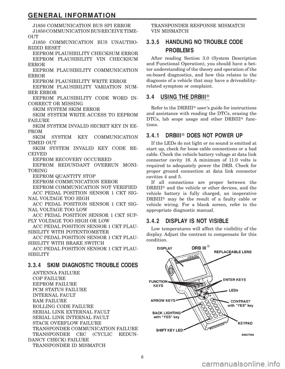
3.4.2 DISPLAY IS NOT VISIBLE
Low temperatures will affect the visibility of the
display. Adjust the contrast to compensate for this
condition.
6
GENERAL INFORMATION
Page 1336 of 4284
Symptom:
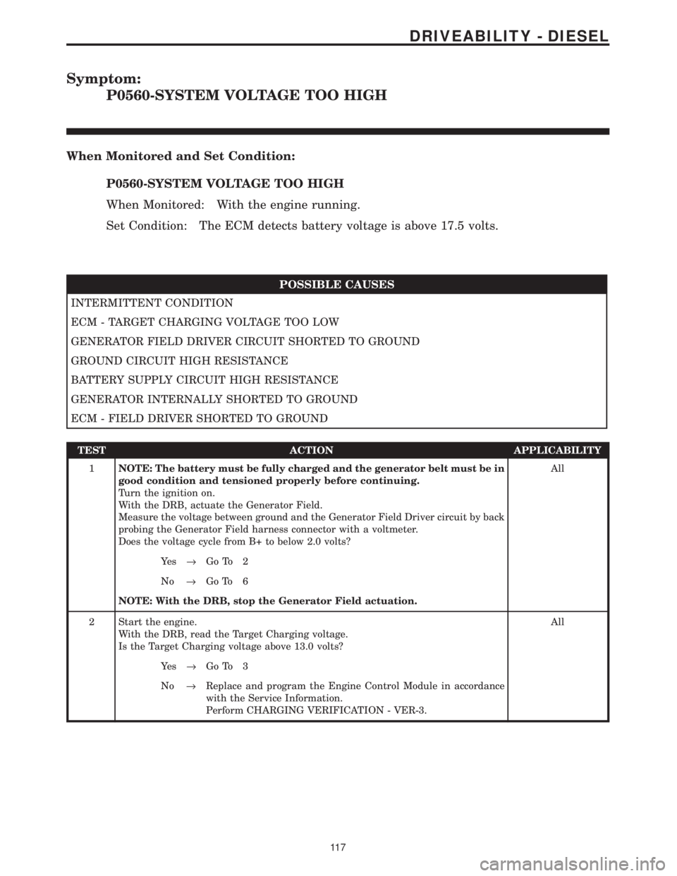
P0560-SYSTEM VOLTAGE TOO HIGH
When Monitored and Set Condition:
P0560-SYSTEM VOLTAGE TOO HIGH
When Monitored: With the engine running.
Set Condition: The ECM detects battery voltage is above 17.5 volts.
POSSIBLE CAUSES
INTERMITTENT CONDITION
ECM - TARGET CHARGING VOLTAGE TOO LOW
GENERATOR FIELD DRIVER CIRCUIT SHORTED TO GROUND
GROUND CIRCUIT HIGH RESISTANCE
BATTERY SUPPLY CIRCUIT HIGH RESISTANCE
GENERATOR INTERNALLY SHORTED TO GROUND
ECM - FIELD DRIVER SHORTED TO GROUND
TEST ACTION APPLICABILITY
1NOTE: The battery must be fully charged and the generator belt must be in
good condition and tensioned properly before continuing.
Turn the ignition on.
With the DRB, actuate the Generator Field.
Measure the voltage between ground and the Generator Field Driver circuit by back
probing the Generator Field harness connector with a voltmeter.
Does the voltage cycle from B+ to below 2.0 volts?All
Ye s®Go To 2
No®Go To 6
NOTE: With the DRB, stop the Generator Field actuation.
2 Start the engine.
With the DRB, read the Target Charging voltage.
Is the Target Charging voltage above 13.0 volts?All
Ye s®Go To 3
No®Replace and program the Engine Control Module in accordance
with the Service Information.
Perform CHARGING VERIFICATION - VER-3.
11 7
DRIVEABILITY - DIESEL
Page 1340 of 4284
TEST ACTION APPLICABILITY
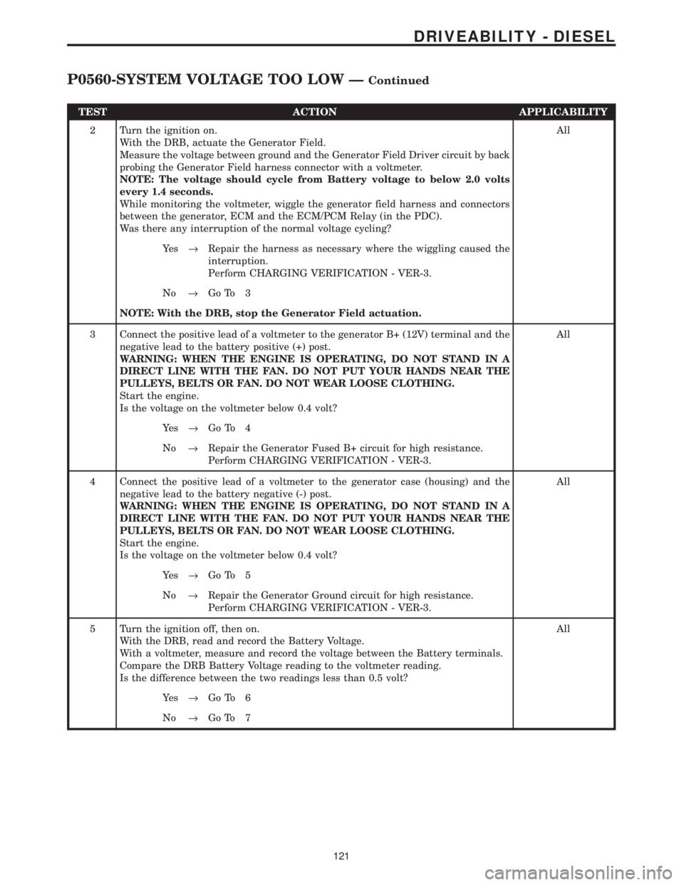
2 Turn the ignition on.
With the DRB, actuate the Generator Field.
Measure the voltage between ground and the Generator Field Driver circuit by back
probing the Generator Field harness connector with a voltmeter.
NOTE: The voltage should cycle from Battery voltage to below 2.0 volts
every 1.4 seconds.
While monitoring the voltmeter, wiggle the generator field harness and connectors
between the generator, ECM and the ECM/PCM Relay (in the PDC).
Was there any interruption of the normal voltage cycling?All
Ye s®Repair the harness as necessary where the wiggling caused the
interruption.
Perform CHARGING VERIFICATION - VER-3.
No®Go To 3
NOTE: With the DRB, stop the Generator Field actuation.
3 Connect the positive lead of a voltmeter to the generator B+ (12V) terminal and the
negative lead to the battery positive (+) post.
WARNING: WHEN THE ENGINE IS OPERATING, DO NOT STAND IN A
DIRECT LINE WITH THE FAN. DO NOT PUT YOUR HANDS NEAR THE
PULLEYS, BELTS OR FAN. DO NOT WEAR LOOSE CLOTHING.
Start the engine.
Is the voltage on the voltmeter below 0.4 volt?All
Ye s®Go To 4
No®Repair the Generator Fused B+ circuit for high resistance.
Perform CHARGING VERIFICATION - VER-3.
4 Connect the positive lead of a voltmeter to the generator case (housing) and the
negative lead to the battery negative (-) post.
WARNING: WHEN THE ENGINE IS OPERATING, DO NOT STAND IN A
DIRECT LINE WITH THE FAN. DO NOT PUT YOUR HANDS NEAR THE
PULLEYS, BELTS OR FAN. DO NOT WEAR LOOSE CLOTHING.
Start the engine.
Is the voltage on the voltmeter below 0.4 volt?All
Ye s®Go To 5
No®Repair the Generator Ground circuit for high resistance.
Perform CHARGING VERIFICATION - VER-3.
5 Turn the ignition off, then on.
With the DRB, read and record the Battery Voltage.
With a voltmeter, measure and record the voltage between the Battery terminals.
Compare the DRB Battery Voltage reading to the voltmeter reading.
Is the difference between the two readings less than 0.5 volt?All
Ye s®Go To 6
No®Go To 7
121
DRIVEABILITY - DIESEL
P0560-SYSTEM VOLTAGE TOO LOW ÐContinued
Page 1443 of 4284
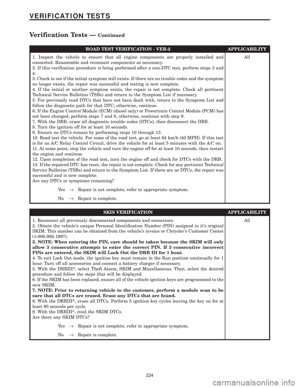
ROAD TEST VERIFICATION - VER-2 APPLICABILITY
1. Inspect the vehicle to ensure that all engine components are properly installed and
connected. Reassemble and reconnect components as necessary.
2. If this verification procedure is being performed after a non-DTC test, perform steps 3 and
4.
3. Check to see if the initial symptom still exists. If there are no trouble codes and the symptom
no longer exists, the repair was successful and testing is now complete.
4. If the initial or another symptom exists, the repair is not complete. Check all pertinent
Technical Service Bulletins (TSBs) and return to the Symptom List if necessary.
5. For previously read DTCs that have not been dealt with, return to the Symptom List and
follow the diagnostic path for that DTC; otherwise, continue.
6. If the Engine Control Module (ECM) (diesel only) or Powertrain Control Module (PCM) has
not been changed, perform steps 7 and 8, otherwise, continue with step 9.
7. With the DRB, erase all diagnostic trouble codes (DTCs), then disconnect the DRB.
8. Turn the ignition off for at least 10 seconds.
9. Ensure no DTCs remain by performing steps 10 through 13.
10. Road test the vehicle. For some of the road test, go at least 64 km/h (40 MPH). If this test
is for an A/C Relay Control Circuit, drive the vehicle for at least 5 minutes with the A/C on.
11. At some point, stop the vehicle and turn the engine off for at least 10 seconds, then restart
the engine and continue.
12. Upon completion of the road test, turn the engine off and check for DTCs with the DRB.
13. If the repaired DTC has reset, the repair is not complete. Check for any pertinent Technical
Service Bulletins (TSBs) and return to the Symptom List. If there are no DTCs, the repair was
successful and is now complete.
Are any DTCs or symptoms remaining?All
Ye s®Repair is not complete, refer to appropriate symptom.
No®Repair is complete.
SKIS VERIFICATION APPLICABILITY
1. Reconnect all previously disconnected components and connectors.
2. Obtain the vehicle's unique Personal Identification Number (PIN) assigned to it's original
SKIM. This number can be obtained from the vehicle's invoice or Chrysler's Customer Center
(1-800-992-1997).
3. NOTE: When entering the PIN, care should be taken because the SKIM will only
allow 3 consecutive attempts to enter the correct PIN. If 3 consecutive incorrect
PINs are entered, the SKIM will Lock Out the DRB III for 1 hour.
4. To exit Lock Out mode, the ignition key must remain in the Run position continually for 1
hour. Turn off all accessories and connect a battery charger if necessary.
5. With the DRBIIIt, select Theft Alarm, SKIM and Miscellaneous. Then, select the desired
procedure and follow the steps that will be displayed.
6. If the SKIM has been replaced, ensure all of the vehicle ignition keys are programmed to the
new SKIM.
7. NOTE: Prior to returning vehicle to the customer, perform a module scan to be
sure that all DTCs are erased. Erase any DTCs that are found.
8. With the DRBIIIt, erase all DTCs. Perform 5 ignition key cycles leaving the key on for at
least 90 seconds per cycle.
9. With the DRBIIIt, read the SKIM DTCs.
Are there any SKIM DTCs?All
Ye s®Repair is not complete, refer to appropriate symptom.
No®Repair is complete.
224
VERIFICATION TESTS
Verification Tests ÐContinued
Page 1455 of 4284
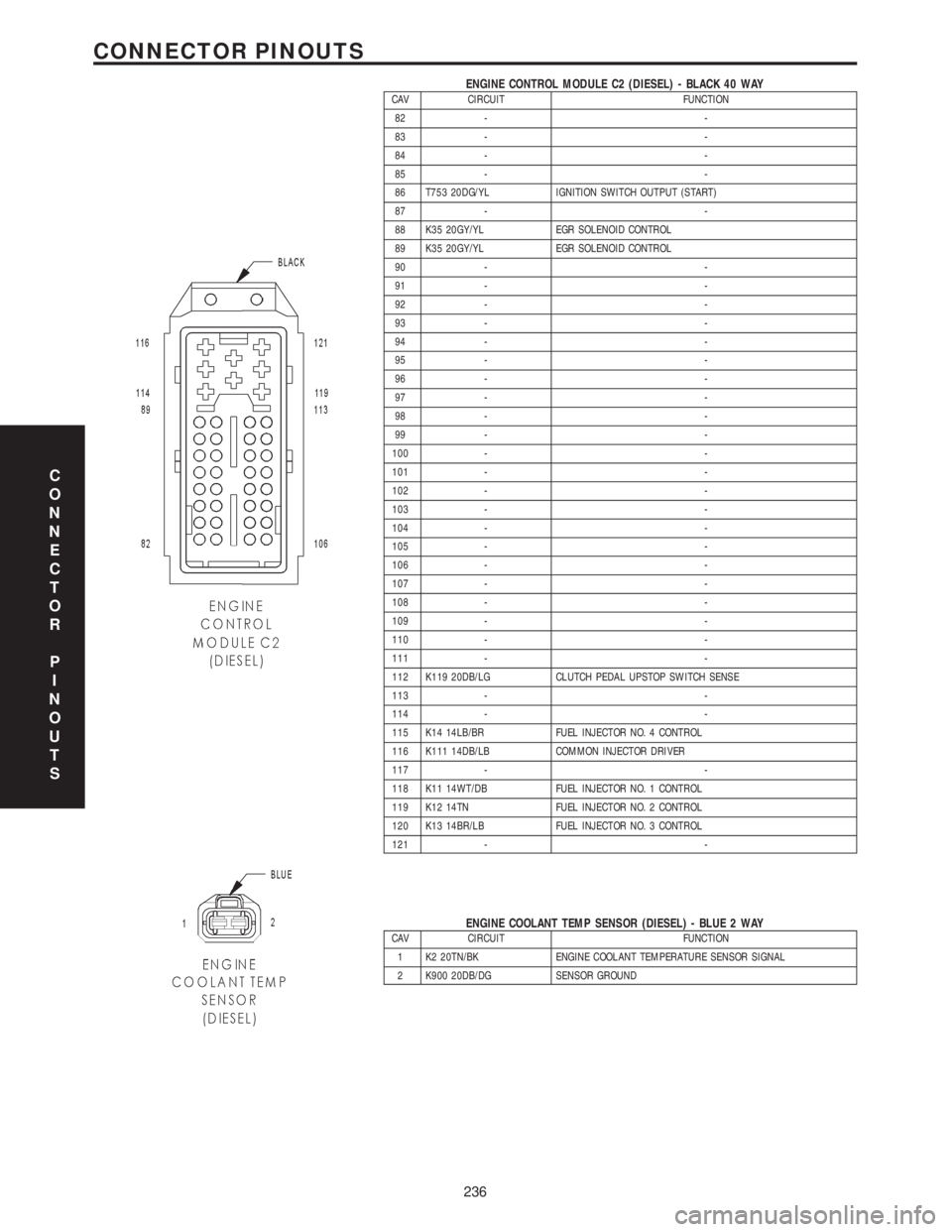
ENGINE CONTROL MODULE C2 (DIESEL) - BLACK 40 WAYCAV CIRCUIT FUNCTION
82 - -
83 - -
84 - -
85 - -
86 T753 20DG/YL IGNITION SWITCH OUTPUT (START)
87 - -
88 K35 20GY/YL EGR SOLENOID CONTROL
89 K35 20GY/YL EGR SOLENOID CONTROL
90 - -
91 - -
92 - -
93 - -
94 - -
95 - -
96 - -
97 - -
98 - -
99 - -
100 - -
101 - -
102 - -
103 - -
104 - -
105 - -
106 - -
107 - -
108 - -
109 - -
110 - -
111 - -
112 K119 20DB/LG CLUTCH PEDAL UPSTOP SWITCH SENSE
113 - -
114 - -
115 K14 14LB/BR FUEL INJECTOR NO. 4 CONTROL
116 K111 14DB/LB COMMON INJECTOR DRIVER
117 - -
118 K11 14WT/DB FUEL INJECTOR NO. 1 CONTROL
119 K12 14TN FUEL INJECTOR NO. 2 CONTROL
120 K13 14BR/LB FUEL INJECTOR NO. 3 CONTROL
121 - -
ENGINE COOLANT TEMP SENSOR (DIESEL) - BLUE 2 WAYCAV CIRCUIT FUNCTION
1 K2 20TN/BK ENGINE COOLANT TEMPERATURE SENSOR SIGNAL
2 K900 20DB/DG SENSOR GROUND
C
O
N
N
E
C
T
O
R
P
I
N
O
U
T
S
236
CONNECTOR PINOUTS
Page 1505 of 4284
transmission in NEUTRAL and turn the ignition
OFF.
(3) On disabled vehicle, place gear selector in park
or neutral and set park brake. Turn off all accesso-
ries.
(4) Connect jumper cables to booster battery. RED
clamp to positive terminal (+). BLACK clamp to neg-
ative terminal (-). DO NOT allow clamps at opposite
end of cables to touch, electrical arc will result.
Review all warnings in this procedure.
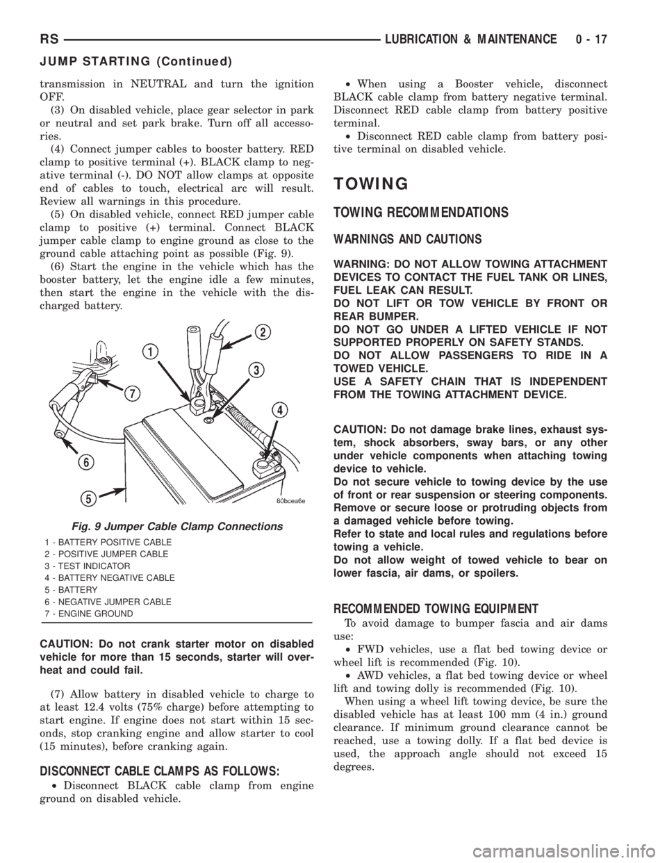
(5) On disabled vehicle, connect RED jumper cable
clamp to positive (+) terminal. Connect BLACK
jumper cable clamp to engine ground as close to the
ground cable attaching point as possible (Fig. 9).
(6) Start the engine in the vehicle which has the
booster battery, let the engine idle a few minutes,
then start the engine in the vehicle with the dis-
charged battery.
CAUTION: Do not crank starter motor on disabled
vehicle for more than 15 seconds, starter will over-
heat and could fail.
(7) Allow battery in disabled vehicle to charge to
at least 12.4 volts (75% charge) before attempting to
start engine. If engine does not start within 15 sec-
onds, stop cranking engine and allow starter to cool
(15 minutes), before cranking again.
DISCONNECT CABLE CLAMPS AS FOLLOWS:
²Disconnect BLACK cable clamp from engine
ground on disabled vehicle.²When using a Booster vehicle, disconnect
BLACK cable clamp from battery negative terminal.
Disconnect RED cable clamp from battery positive
terminal.
²Disconnect RED cable clamp from battery posi-
tive terminal on disabled vehicle.
TOWING
TOWING RECOMMENDATIONS
WARNINGS AND CAUTIONS
WARNING: DO NOT ALLOW TOWING ATTACHMENT
DEVICES TO CONTACT THE FUEL TANK OR LINES,
FUEL LEAK CAN RESULT.
DO NOT LIFT OR TOW VEHICLE BY FRONT OR
REAR BUMPER.
DO NOT GO UNDER A LIFTED VEHICLE IF NOT
SUPPORTED PROPERLY ON SAFETY STANDS.
DO NOT ALLOW PASSENGERS TO RIDE IN A
TOWED VEHICLE.
USE A SAFETY CHAIN THAT IS INDEPENDENT
FROM THE TOWING ATTACHMENT DEVICE.
CAUTION: Do not damage brake lines, exhaust sys-
tem, shock absorbers, sway bars, or any other
under vehicle components when attaching towing
device to vehicle.
Do not secure vehicle to towing device by the use
of front or rear suspension or steering components.
Remove or secure loose or protruding objects from
a damaged vehicle before towing.
Refer to state and local rules and regulations before
towing a vehicle.
Do not allow weight of towed vehicle to bear on
lower fascia, air dams, or spoilers.
RECOMMENDED TOWING EQUIPMENT
To avoid damage to bumper fascia and air dams
use:
²FWD vehicles, use a flat bed towing device or
wheel lift is recommended (Fig. 10).
²AWD vehicles, a flat bed towing device or wheel
lift and towing dolly is recommended (Fig. 10).
When using a wheel lift towing device, be sure the
disabled vehicle has at least 100 mm (4 in.) ground
clearance. If minimum ground clearance cannot be
reached, use a towing dolly. If a flat bed device is
used, the approach angle should not exceed 15
degrees.
Fig. 9 Jumper Cable Clamp Connections
1 - BATTERY POSITIVE CABLE
2 - POSITIVE JUMPER CABLE
3 - TEST INDICATOR
4 - BATTERY NEGATIVE CABLE
5 - BATTERY
6 - NEGATIVE JUMPER CABLE
7 - ENGINE GROUND
RSLUBRICATION & MAINTENANCE0-17
JUMP STARTING (Continued)
Page 1514 of 4284
JUMP STARTING
STANDARD PROCEDURE - JUMP STARTING
(1) Raise hood on disabled vehicle and visually
inspect engine compartment for:
²Battery cable clamp condition, clean if necessary.
²Frozen battery.
²Yellow or bright color test indicator, if equipped.
²Low battery fluid level.
²Generator drive belt condition and tension.
²Fuel fumes or leakage, correct if necessary.
CAUTION: If the cause of starting problem on dis-
abled vehicle is severe, damage to booster vehicle
charging system can result.
(2) When using another vehicle as a booster
source, park the booster vehicle within cable reach.
Turn off all accessories, set the parking brake, place
the automatic transmission in PARK or the manual
transmission in NEUTRAL and turn the ignition
OFF.
(3)
On disabled vehicle, place gear selector in park
or neutral and set park brake. Turn off all accessories.
(4) Connect jumper cables to booster battery. RED
clamp to positive terminal (+). BLACK clamp to neg-
ative terminal (-). DO NOT allow clamps at opposite
end of cables to touch, electrical arc will result.
Review all warnings in this procedure.
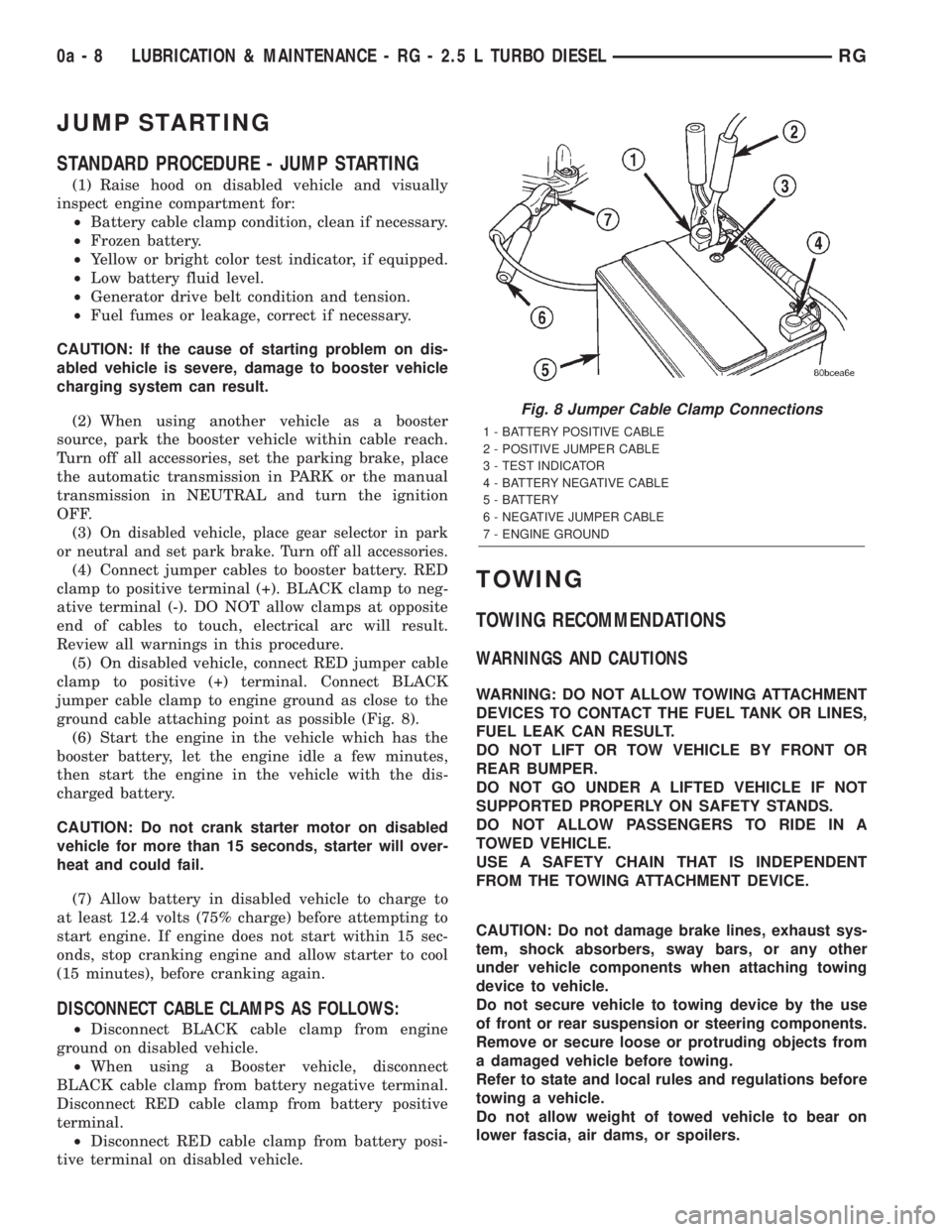
(5) On disabled vehicle, connect RED jumper cable
clamp to positive (+) terminal. Connect BLACK
jumper cable clamp to engine ground as close to the
ground cable attaching point as possible (Fig. 8).
(6) Start the engine in the vehicle which has the
booster battery, let the engine idle a few minutes,
then start the engine in the vehicle with the dis-
charged battery.
CAUTION: Do not crank starter motor on disabled
vehicle for more than 15 seconds, starter will over-
heat and could fail.
(7) Allow battery in disabled vehicle to charge to
at least 12.4 volts (75% charge) before attempting to
start engine. If engine does not start within 15 sec-
onds, stop cranking engine and allow starter to cool
(15 minutes), before cranking again.
DISCONNECT CABLE CLAMPS AS FOLLOWS:
²Disconnect BLACK cable clamp from engine
ground on disabled vehicle.
²When using a Booster vehicle, disconnect
BLACK cable clamp from battery negative terminal.
Disconnect RED cable clamp from battery positive
terminal.
²Disconnect RED cable clamp from battery posi-
tive terminal on disabled vehicle.
TOWING
TOWING RECOMMENDATIONS
WARNINGS AND CAUTIONS
WARNING: DO NOT ALLOW TOWING ATTACHMENT
DEVICES TO CONTACT THE FUEL TANK OR LINES,
FUEL LEAK CAN RESULT.
DO NOT LIFT OR TOW VEHICLE BY FRONT OR
REAR BUMPER.
DO NOT GO UNDER A LIFTED VEHICLE IF NOT
SUPPORTED PROPERLY ON SAFETY STANDS.
DO NOT ALLOW PASSENGERS TO RIDE IN A
TOWED VEHICLE.
USE A SAFETY CHAIN THAT IS INDEPENDENT
FROM THE TOWING ATTACHMENT DEVICE.
CAUTION: Do not damage brake lines, exhaust sys-
tem, shock absorbers, sway bars, or any other
under vehicle components when attaching towing
device to vehicle.
Do not secure vehicle to towing device by the use
of front or rear suspension or steering components.
Remove or secure loose or protruding objects from
a damaged vehicle before towing.
Refer to state and local rules and regulations before
towing a vehicle.
Do not allow weight of towed vehicle to bear on
lower fascia, air dams, or spoilers.
Fig. 8 Jumper Cable Clamp Connections
1 - BATTERY POSITIVE CABLE
2 - POSITIVE JUMPER CABLE
3 - TEST INDICATOR
4 - BATTERY NEGATIVE CABLE
5 - BATTERY
6 - NEGATIVE JUMPER CABLE
7 - ENGINE GROUND
0a - 8 LUBRICATION & MAINTENANCE - RG - 2.5 L TURBO DIESELRG