2001 CHRYSLER VOYAGER ABS
[x] Cancel search: ABSPage 16 of 4284
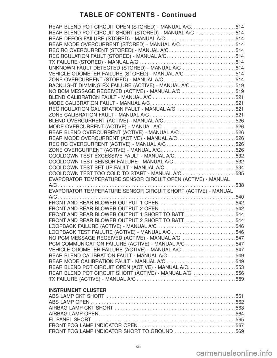
TABLE OF CONTENTS - Continued
REAR BLEND POT CIRCUIT OPEN (STORED) - MANUAL A/C.................514
REAR BLEND POT CIRCUIT SHORT (STORED) - MANUAL A/C...............514
REAR DEFOG FAILURE (STORED) - MANUAL A/C..........................514
REAR MODE OVERCURRENT (STORED) - MANUAL A/C.....................514
RECIRC OVERCURRENT (STORED) - MANUAL A/C.........................514
RECIRCULATION FAULT (STORED) - MANUAL A/C..........................514
TX FAILURE (STORED) - MANUAL A/C....................................514
UNKNOWN FAULT DETECTED (STORED) - MANUAL A/C....................514
VEHICLE ODOMETER FAILURE (STORED) - MANUAL A/C...................514
ZONE OVERCURRENT (STORED) - MANUAL A/C...........................514
BACKLIGHT DIMMING RX FAILURE (ACTIVE) - MANUAL A/C.................519
NO BCM MESSAGE RECEIVED (ACTIVE) - MANUAL A/C....................519
BLEND CALIBRATION FAULT - MANUAL A/C...............................521
MODE CALIBRATION FAULT - MANUAL A/C................................521
RECIRCULATION CALIBRATION FAULT - MANUAL A/C......................521
ZONE CALIBRATION FAULT - MANUAL A/C................................521
BLEND OVERCURRENT (ACTIVE) - MANUAL A/C...........................526
MODE OVERCURRENT (ACTIVE) - MANUAL A/C...........................526
REAR BLEND OVERCURRENT (ACTIVE) - MANUAL A/C.....................526
REAR MODE OVERCURRENT (ACTIVE) - MANUAL A/C......................526
RECIRC OVERCURRENT (ACTIVE) - MANUAL A/C..........................526
ZONE OVERCURRENT (ACTIVE) - MANUAL A/C............................526
COOLDOWN TEST EXCESSIVE FAULT - MANUAL A/C.......................532
COOLDOWN TEST SENSOR FAILURE - MANUAL A/C.......................532
COOLDOWN TEST SET UP FAULT - MANUAL A/C..........................534
COOLDOWN TEST TOO COLD TO START - MANUAL A/C....................535
EVAPORATOR TEMPERATURE SENSOR CIRCUIT OPEN (ACTIVE) - MANUAL
A/C..................................................................538
EVAPORATOR TEMPERATURE SENSOR CIRCUIT SHORT (ACTIVE) - MANUAL
A/C..................................................................540
FRONT AND REAR BLOWER OUTPUT 1 OPEN............................542
FRONT AND REAR BLOWER OUTPUT 2 OPEN............................542
FRONT AND REAR BLOWER OUTPUT 1 SHORT TO BATT...................544
FRONT AND REAR BLOWER OUTPUT 2 SHORT TO BATT...................544
LOOPBACK FAILURE (ACTIVE) - MANUAL A/C.............................546
LOOPBACK TEST FAILURE (ACTIVE) - MANUAL A/C........................546
NO PCM MESSAGE RECEIVED (ACTIVE) - MANUAL A/C....................547
PCM COMMUNICATION FAILURE (ACTIVE) - MANUAL A/C...................547
VEHICLE ODOMETER FAILURE (ACTIVE) - MANUAL A/C....................547
REAR BLEND CALIBRATION FAULT - MANUAL A/C.........................549
REAR MODE CALIBRATION FAULT - MANUAL A/C..........................549
REAR BLEND POT CIRCUIT OPEN (ACTIVE) - MANUAL A/C..................553
REAR BLEND POT CIRCUIT SHORT (ACTIVE) - MANUAL A/C................556
TX FAILURE (ACTIVE) - MANUAL A/C.....................................559
INSTRUMENT CLUSTER
ABS LAMP CKT SHORT................................................561
ABS LAMP OPEN......................................................562
AIRBAG LAMP CKT SHORT.............................................563
AIRBAG LAMP OPEN...................................................564
EL PANEL SHORT.....................................................565
FRONT FOG LAMP INDICATOR OPEN....................................567
FRONT FOG LAMP INDICATOR SHORT TO GROUND.......................569
xiii
Page 17 of 4284
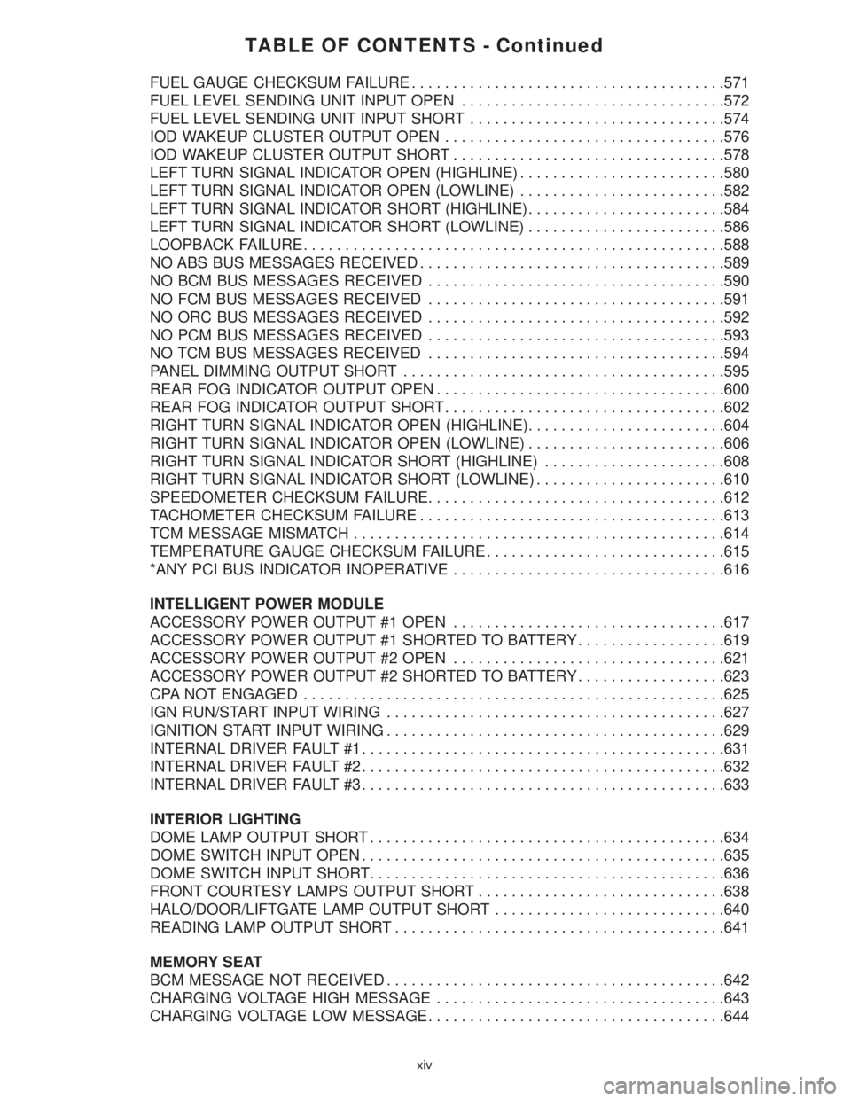
TABLE OF CONTENTS - Continued
FUEL GAUGE CHECKSUM FAILURE......................................571
FUEL LEVEL SENDING UNIT INPUT OPEN................................572
FUEL LEVEL SENDING UNIT INPUT SHORT...............................574
IOD WAKEUP CLUSTER OUTPUT OPEN..................................576
IOD WAKEUP CLUSTER OUTPUT SHORT.................................578
LEFT TURN SIGNAL INDICATOR OPEN (HIGHLINE).........................580
LEFT TURN SIGNAL INDICATOR OPEN (LOWLINE).........................582
LEFT TURN SIGNAL INDICATOR SHORT (HIGHLINE)........................584
LEFT TURN SIGNAL INDICATOR SHORT (LOWLINE)........................586
LOOPBACK FAILURE...................................................588
NO ABS BUS MESSAGES RECEIVED.....................................589
NO BCM BUS MESSAGES RECEIVED....................................590
NO FCM BUS MESSAGES RECEIVED....................................591
NO ORC BUS MESSAGES RECEIVED....................................592
NO PCM BUS MESSAGES RECEIVED....................................593
NO TCM BUS MESSAGES RECEIVED....................................594
PANEL DIMMING OUTPUT SHORT.......................................595
REAR FOG INDICATOR OUTPUT OPEN...................................600
REAR FOG INDICATOR OUTPUT SHORT..................................602
RIGHT TURN SIGNAL INDICATOR OPEN (HIGHLINE)........................604
RIGHT TURN SIGNAL INDICATOR OPEN (LOWLINE)........................606
RIGHT TURN SIGNAL INDICATOR SHORT (HIGHLINE)......................608
RIGHT TURN SIGNAL INDICATOR SHORT (LOWLINE).......................610
SPEEDOMETER CHECKSUM FAILURE....................................612
TACHOMETER CHECKSUM FAILURE.....................................613
TCM MESSAGE MISMATCH.............................................614
TEMPERATURE GAUGE CHECKSUM FAILURE.............................615
*ANY PCI BUS INDICATOR INOPERATIVE.................................616
INTELLIGENT POWER MODULE
ACCESSORY POWER OUTPUT #1 OPEN.................................617
ACCESSORY POWER OUTPUT #1 SHORTED TO BATTERY..................619
ACCESSORY POWER OUTPUT #2 OPEN.................................621
ACCESSORY POWER OUTPUT #2 SHORTED TO BATTERY..................623
CPA NOT ENGAGED...................................................625
IGN RUN/START INPUT WIRING.........................................627
IGNITION START INPUT WIRING.........................................629
INTERNAL DRIVER FAULT #1............................................631
INTERNAL DRIVER FAULT #2............................................632
INTERNAL DRIVER FAULT #3............................................633
INTERIOR LIGHTING
DOME LAMP OUTPUT SHORT...........................................634
DOME SWITCH INPUT OPEN............................................635
DOME SWITCH INPUT SHORT...........................................636
FRONT COURTESY LAMPS OUTPUT SHORT..............................638
HALO/DOOR/LIFTGATE LAMP OUTPUT SHORT............................640
READING LAMP OUTPUT SHORT........................................641
MEMORY SEAT
BCM MESSAGE NOT RECEIVED.........................................642
CHARGING VOLTAGE HIGH MESSAGE...................................643
CHARGING VOLTAGE LOW MESSAGE....................................644
xiv
Page 59 of 4284
WARNING: BEFORE ROAD TESTING A
VEHICLE, BE SURE THAT ALL
COMPONENTS ARE REASSEMBLED.
DURING THE TEST DRIVE, DO NOT TRY TO
READ THE DRBIIITSCREEN WHILE IN
MOTION. DO NOT HANG THE DRBIIITFROM
THE REAR VIEW MIRROR OR OPERATE IT
YOURSELF. HAVE AN ASSISTANT
AVAILABLE TO OPERATE THE DRBIIIT.
5.0 REQUIRED TOOLS AND
EQUIPMENT
DRBIIIt(diagnostic read-out box)
Jumper wires
Ohmmeter
Voltmeter
Sentry Key Tester
Test Light
8310 Airbag System Load Tool
8443 SRS Airbag System Load Tool
Diagnostic Junction Port Tester 8339
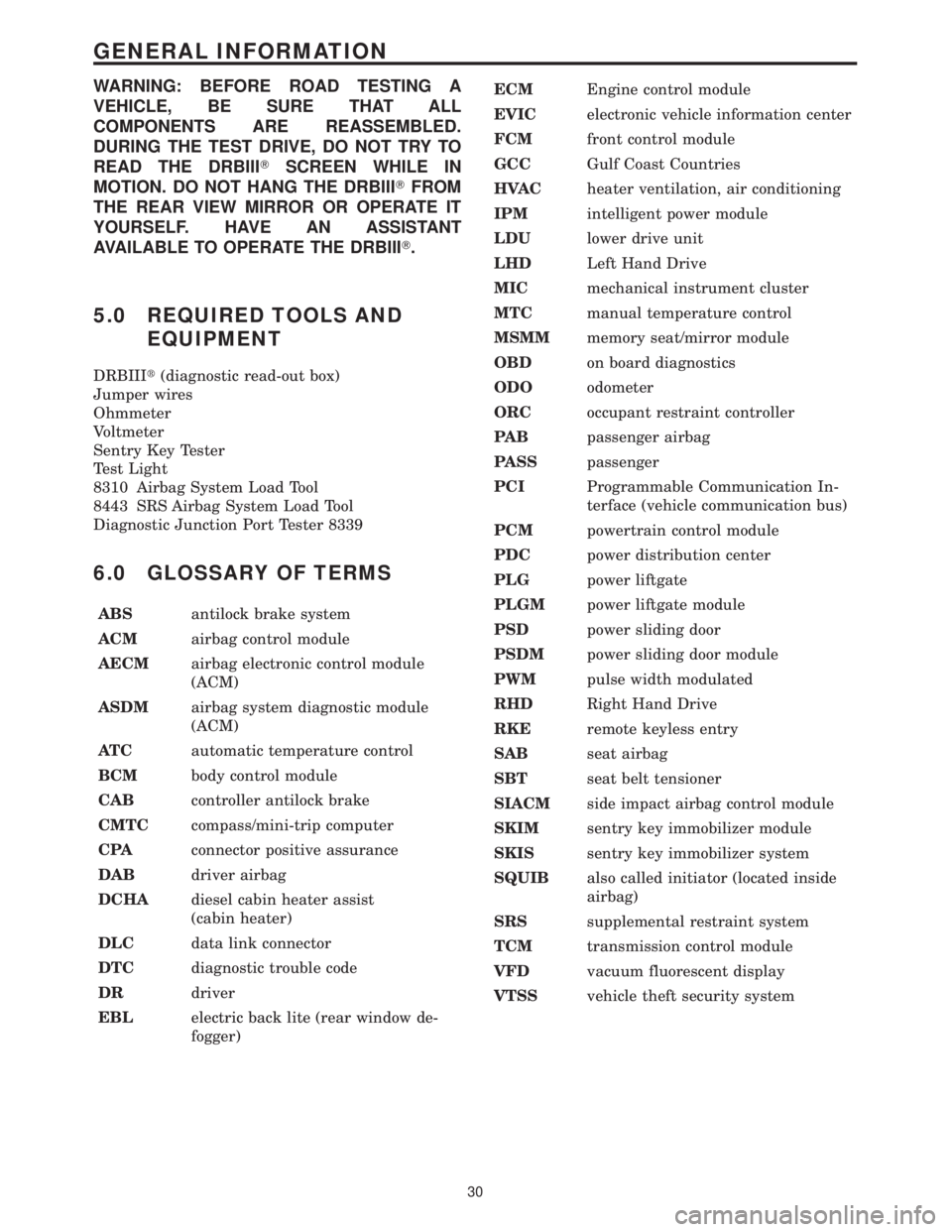
6.0 GLOSSARY OF TERMS
ABSantilock brake system
ACMairbag control module
AECMairbag electronic control module
(ACM)
ASDMairbag system diagnostic module
(ACM)
AT Cautomatic temperature control
BCMbody control module
CABcontroller antilock brake
CMTCcompass/mini-trip computer
CPAconnector positive assurance
DABdriver airbag
DCHAdiesel cabin heater assist
(cabin heater)
DLCdata link connector
DTCdiagnostic trouble code
DRdriver
EBLelectric back lite (rear window de-
fogger)ECMEngine control module
EVICelectronic vehicle information center
FCMfront control module
GCCGulf Coast Countries
HVACheater ventilation, air conditioning
IPMintelligent power module
LDUlower drive unit
LHDLeft Hand Drive
MICmechanical instrument cluster
MTCmanual temperature control
MSMMmemory seat/mirror module
OBDon board diagnostics
ODOodometer
ORCoccupant restraint controller
PA Bpassenger airbag
PASSpassenger
PCIProgrammable Communication In-
terface (vehicle communication bus)
PCMpowertrain control module
PDCpower distribution center
PLGpower liftgate
PLGMpower liftgate module
PSDpower sliding door
PSDMpower sliding door module
PWMpulse width modulated
RHDRight Hand Drive
RKEremote keyless entry
SABseat airbag
SBTseat belt tensioner
SIACMside impact airbag control module
SKIMsentry key immobilizer module
SKISsentry key immobilizer system
SQUIBalso called initiator (located inside
airbag)
SRSsupplemental restraint system
TCMtransmission control module
VFDvacuum fluorescent display
VTSSvehicle theft security system
30
GENERAL INFORMATION
Page 382 of 4284

Symptom:
IGNITION RUN OUTPUT SHORT
When Monitored and Set Condition:
IGNITION RUN OUTPUT SHORT
When Monitored: With the ignition on and battery voltage greater than 10.4 volts.
Set Condition: The Ignition Switch Output circuit(s) from the BCM to the HVAC,
Overhead Console, or the ABS controller are open or go below 0.5 volt for more than 2
seconds.
POSSIBLE CAUSES
TEST FOR CURRENT DTC'S
BODY CONTROL MODULE IGNITION OUTPUT INOPERATIVE (HVAC)
BODY CONTROL MODULE IGNITION OUTPUT CIRCUIT OPEN (HVAC)
BODY CONTROL MODULE IGNITION OUTPUT CIRCUIT SHORTED (HVAC)
BODY CONTROL MODULE IGNITION OUTPUT INOPERATIVE (OVERHEAD)
BODY CONTROL MODULE IGNITION OUTPUT CIRCUIT OPEN (OVERHEAD)
BODY CONTROL MODULE IGNITION OUTPUT CIRCUIT SHORTED (OVERHEAD)
BODY CONTROL MODULE IGNITION OUTPUT INOPERATIVE (ABS)
BODY CONTROL MODULE IGNITION OUTPUT CIRCUIT OPEN (ABS)
BODY CONTROL MODULE IGNITION OUTPUT CIRCUIT SHORTED (ABS)
BODY CONTROL MODULE
TEST ACTION APPLICABILITY
1 With the DRBIIIt, record and erase DTC's.
Cycle the ignition from ON to OFF.
Start the vehicle and observe the DRBIIIt.
With the DRBIIIt, read DTC's.
Does the DRBIIItdisplay IGNITION RUN OUTPUT SHORT?All
Ye s®Go To 2
No®The condition that caused this DTC is currently not present. Use
the wiring diagram/schematic as a guide, and inspect the related
wiring harness for a possible intermittent condition.
2 A failure in the HVAC, Overhead Console, or the ABS system could cause this DTC
to set. The Ignition Switch Run (HVAC) circuit will be diagnosed first.
Continue to the HVAC circuit for further diagnosis.All
HVAC circuit diagnostics.
Go To 3
353
COMMUNICATION
Page 383 of 4284

TEST ACTION APPLICABILITY
3 Turn the ignition off.
Disconnect the HVAC connector.
Turn the ignition on.
Measure the voltage of the Ignition Switch Run (HVAC) circuit in the HVAC
controller connector.
Is the voltage above 10.0 volts?All
Ye s®Go To Test #6. The condition that caused the DTC to set is not
present on this circuit. Further diagnostics are required to
determine the cause of the DTC.
No®Go To 4
4 Gain access to the Body Control Module C4 connector.
Turn the ignition on.
While back probing, measure the voltage of the Ignition Switch Run (HVAC) circuit.
Is the voltage above 10.0 volts?All
Ye s®Repair the Ignition Switch Run (HVAC) circuit for an open.
Perform BODY VERIFICATION TEST - VER 1.
No®Go To 5
5 Turn the ignition off.
Disconnect the Body Control Module C4 connector.
Measure the resistance between ground and the Ignition Switch Run (HVAC) circuit
in the HVAC controller connector.
Is the resistance below 5.0 ohms?All
Ye s®Repair the Ignition Switch Run (HVAC) circuit for a short to
ground.
Perform BODY VERIFICATION TEST - VER 1.
No®Go To 6
6 A failure in the HVAC, Overhead Console, or the ABS system could cause this DTC
to set. The Ignition Switch Output (Overhead Console) circuit will be diagnosed.
Continue to the OVERHEAD CONSOLE circuit for further diagnosis.All
OVERHEAD CONSOLE circuit diagnostics.
Go To 7
7 Turn the ignition off.
Disconnect the Overhead Console connector.
Turn the ignition on.
Measure the voltage of the Ignition Switch Output circuit in the Overhead Console
connector.
Is the voltage above 10.0 volts?All
Ye s®Go To Test #10. The condition that caused the DTC to set is not
present on this circuit. Further diagnostics are required to
determine the cause of the DTC.
No®Go To 8
354
COMMUNICATION
IGNITION RUN OUTPUT SHORT ÐContinued
Page 384 of 4284
TEST ACTION APPLICABILITY
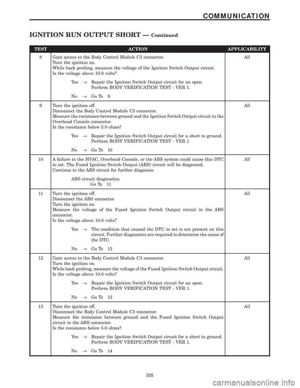
8 Gain access to the Body Control Module C3 connector.
Turn the ignition on.
While back probing, measure the voltage of the Ignition Switch Output circuit.
Is the voltage above 10.0 volts?All
Ye s®Repair the Ignition Switch Output circuit for an open.
Perform BODY VERIFICATION TEST - VER 1.
No®Go To 9
9 Turn the ignition off.
Disconnect the Body Control Module C3 connector.
Measure the resistance between ground and the Ignition Switch Output circuit in the
Overhead Console connector.
Is the resistance below 5.0 ohms?All
Ye s®Repair the Ignition Switch Output circuit for a short to ground.
Perform BODY VERIFICATION TEST - VER 1.
No®Go To 10
10 A failure in the HVAC, Overhead Console, or the ABS system could cause this DTC
to set. The Fused Ignition Switch Output (ABS) circuit will be diagnosed.
Continue to the ABS circuit for further diagnosis.All
ABS circuit diagnostics.
Go To 11
11 Turn the ignition off.
Disconnect the ABS connector.
Turn the ignition on.
Measure the voltage of the Fused Ignition Switch Output circuit in the ABS
connector.
Is the voltage above 10.0 volts?All
Ye s®The condition that caused the DTC to set is not present on this
circuit. Further diagnostics are required to determine the cause of
the DTC.
No®Go To 12
12 Gain access to the Body Control Module C3 connector.
Turn the ignition on.
While back probing, measure the voltage of the Fused Ignition Switch Output circuit.
Is the voltage above 10.0 volts?All
Ye s®Repair the Ignition Switch Output circuit for an open.
Perform BODY VERIFICATION TEST - VER 1.
No®Go To 13
13 Turn the ignition off.
Disconnect the Body Control Module C3 connector.
Measure the resistance between ground and the Fused Ignition Switch Output
circuit in the ABS connector.
Is the resistance below 5.0 ohms?All
Ye s®Repair the Ignition Switch Output circuit for a short to ground.
Perform BODY VERIFICATION TEST - VER 1.
No®Go To 14
355
COMMUNICATION
IGNITION RUN OUTPUT SHORT ÐContinued
Page 428 of 4284
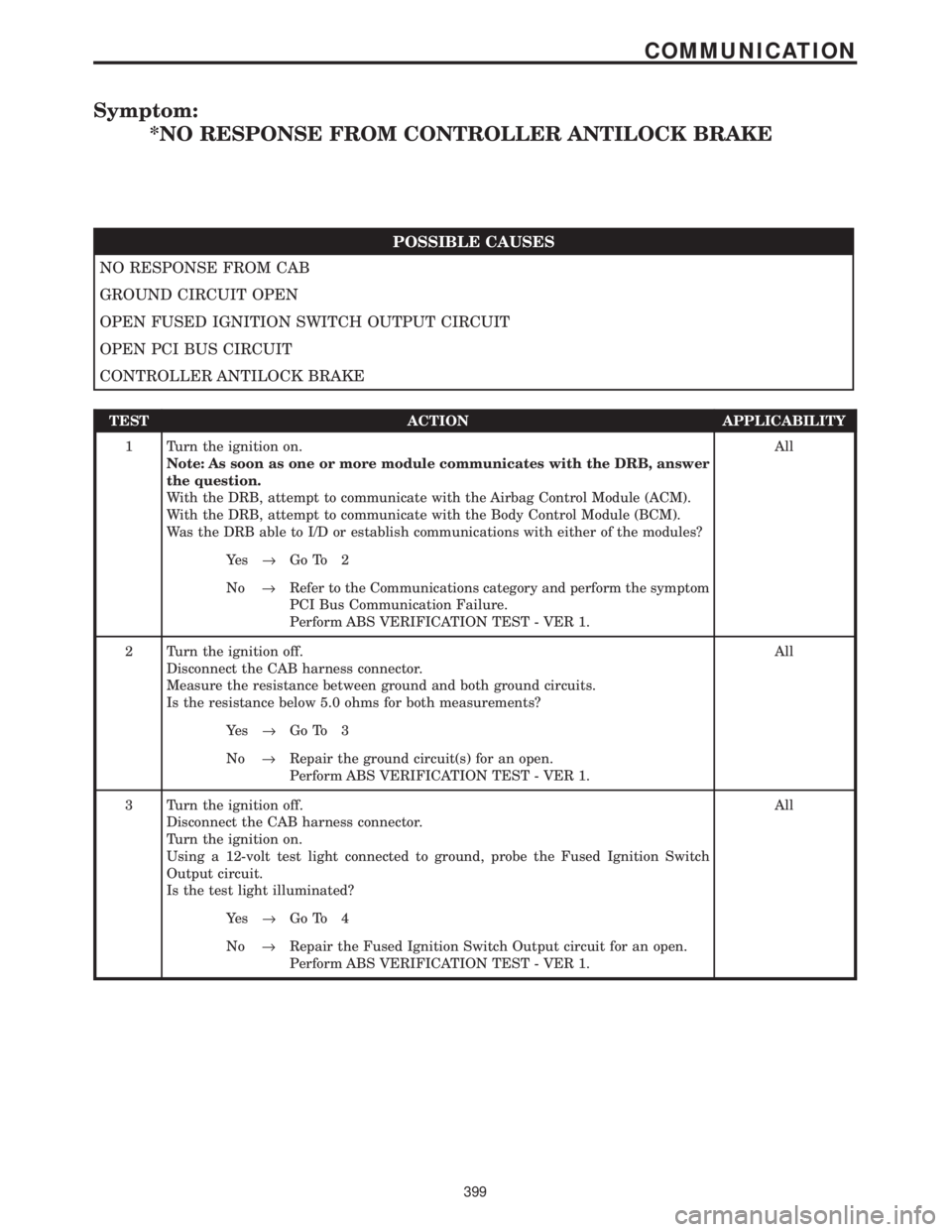
Symptom:
*NO RESPONSE FROM CONTROLLER ANTILOCK BRAKE
POSSIBLE CAUSES
NO RESPONSE FROM CAB
GROUND CIRCUIT OPEN
OPEN FUSED IGNITION SWITCH OUTPUT CIRCUIT
OPEN PCI BUS CIRCUIT
CONTROLLER ANTILOCK BRAKE
TEST ACTION APPLICABILITY
1 Turn the ignition on.
Note: As soon as one or more module communicates with the DRB, answer
the question.
With the DRB, attempt to communicate with the Airbag Control Module (ACM).
With the DRB, attempt to communicate with the Body Control Module (BCM).
Was the DRB able to I/D or establish communications with either of the modules?All
Ye s®Go To 2
No®Refer to the Communications category and perform the symptom
PCI Bus Communication Failure.
Perform ABS VERIFICATION TEST - VER 1.
2 Turn the ignition off.
Disconnect the CAB harness connector.
Measure the resistance between ground and both ground circuits.
Is the resistance below 5.0 ohms for both measurements?All
Ye s®Go To 3
No®Repair the ground circuit(s) for an open.
Perform ABS VERIFICATION TEST - VER 1.
3 Turn the ignition off.
Disconnect the CAB harness connector.
Turn the ignition on.
Using a 12-volt test light connected to ground, probe the Fused Ignition Switch
Output circuit.
Is the test light illuminated?All
Ye s®Go To 4
No®Repair the Fused Ignition Switch Output circuit for an open.
Perform ABS VERIFICATION TEST - VER 1.
399
COMMUNICATION
Page 429 of 4284
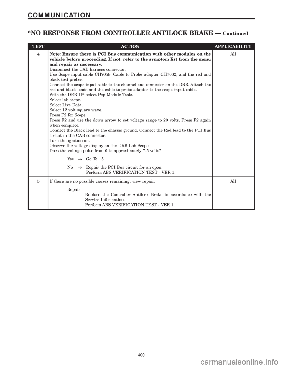
TEST ACTION APPLICABILITY
4Note: Ensure there is PCI Bus communication with other modules on the
vehicle before proceeding. If not, refer to the symptom list from the menu
and repair as necessary.
Disconnect the CAB harness connector.
Use Scope input cable CH7058, Cable to Probe adapter CH7062, and the red and
black test probes.
Connect the scope input cable to the channel one connector on the DRB. Attach the
red and black leads and the cable to probe adapter to the scope input cable.
With the DRBIIItselect Pep Module Tools.
Select lab scope.
Select Live Data.
Select 12 volt square wave.
Press F2 for Scope.
Press F2 and use the down arrow to set voltage range to 20 volts. Press F2 again
when complete.
Connect the Black lead to the chassis ground. Connect the Red lead to the PCI Bus
circuit in the CAB connector.
Turn the ignition on.
Observe the voltage display on the DRB Lab Scope.
Does the voltage pulse from 0 to approximately 7.5 volts?All
Ye s®Go To 5
No®Repair the PCI Bus circuit for an open.
Perform ABS VERIFICATION TEST - VER 1.
5 If there are no possible causes remaining, view repair. All
Repair
Replace the Controller Antilock Brake in accordance with the
Service Information.
Perform ABS VERIFICATION TEST - VER 1.
400
COMMUNICATION
*NO RESPONSE FROM CONTROLLER ANTILOCK BRAKE ÐContinued