2001 CHRYSLER VOYAGER headlamp
[x] Cancel search: headlampPage 1977 of 4284
recall memory settings when the Driver 1 or Driver 2
push buttons of the memory switch on the driver side
front door trim panel are depressed.
²SOUND HORN ON LOCK?- The options
include Yes and No. The default is No. When Yes is
selected, a short horn chirp will provide an audible
confirmation when the RKE receiver recognizes a
valid Lock signal from an RKE transmitter. When No
is selected, no horn chirp will occur with the RKE
Lock event. This feature may be selected indepen-
dent of theFLASH LIGHTS WITH LOCKS?pro-
grammable feature.
²FLASH LIGHTS WITH LOCKS?- The options
include Yes and No. The default is Yes. When Yes is
selected, a single flash of the hazard warning lamps
will provide an optical confirmation when the RKE
receiver recognizes a valid Lock signal from an RKE
transmitter, and two flashes of the same lamps will
occur when the RKE receiver recognizes a valid
Unlock signal from an RKE transmitter. When No is
selected, no lamp flash will occur with the RKE Lock
or Unlock event. This feature may be selected inde-
pendent of theSOUND HORN ON LOCK?pro-
grammable feature.
²HEADLAMP DELAY =- The options include
Off, 30 Sec, 60 Sec, and 90 Sec. The default is 90 Sec.
When a time interval is selected, the headlamps will
remain on for that length of time when the head-
lamps are turned off after the ignition is turned off,
or if the Auto mode is selected on vehicles with the
Auto Headlamps option. When Off is selected, the
headlamp delay feature is disabled.
²HEADLAMPS ON WITH WIPERS?- This pro-
grammable feature only applies to vehicles equipped
with the optional Auto Headlamps. The options
include Yes and No. The default is No. When Yes is
selected, the headlamps will turn on automatically
when the windshield wipers are turned on. The head-
lamps will turn off when the wipers are turned off,
as long as the headlamp switch is in the Auto or Off
positions. When No is selected, the headlamps will
only turn on if manually selected or if the Auto mode
is selected and the outside ambient light levels dic-
tate that they should be on.
²POWER ACCESSORY DELAY?- The options
include Yes and No. The default is Yes. When No is
selected, the accessory powered components will turn
off automatically when the ignition key is turned off.
When Yes is selected, the accessory powered compo-
nents will remain on for 45 seconds when the igni-
tion key is turned off.
REMOVAL
(1) Disconnect and isolate the battery negative
cable.(2) Remove overhead console. Refer to Overhead
Console Removal and Installation in this section(Re-
fer to 8 - ELECTRICAL/OVERHEAD CONSOLE -
REMOVAL) .
(3) Remove the ten screws holding the EVIC mod-
ule in the overhead console.
(4) Remove EVIC module from console assembly.
INSTALLATION
(1) Position the EVIC module in the overhead con-
sole.
(2) Install the ten screws holding the EVIC module
in the overhead console.
(3) Install the overhead console. Refer to Overhead
Console Removal and Installation in this section.
(4) Connect the battery negative cable.
NOTE: If a new EVIC module has been installed, the
compass will have to be calibrated and the variance
set. Refer to Compass Variation Adjustment and
Compass Calibration in the Service Procedures sec-
tion of this group for the procedures.
COMPASS/MINI-TRIP
COMPUTER
DESCRIPTION
The Compass Mini-Trip Computer (CMTC) and
Compass Temperature (CT) computer are modules
located in the overhead console. Vehicles are
equipped with either the CMTC or the CT computers
not both. The CMTC is different in the fact that it is
equipped with the mini-trip feature. The CMTC, CT
consists of a electronic control module with a vacuum
fluorescent display (VFD) and function switches. The
CMTC, CT consists of a electronic module that dis-
plays compass, trip computer (CMTC only), and tem-
perature features. Actuating the STEP push button
(CMTC only) will cause the CMTC to change mode of
operation when ignition is ON. Actuating the STEP
push button (CMTC only) will cause the CMTC to
change mode of operation when ignition is ON.
Example:
²Average miles per gallon (ECO)
²Distance to empty (DTE)
²Instant miles per gallon (ECO)
²Trip odometer (ODO)
²Elapsed time (ET)
²Off
Actuating the C/T push button will cause the
CMTC, CT to change to Compass/Temperature dis-
play.
RSOVERHEAD CONSOLE8M-9
ELECTRONIC VEHICLE INFO CENTER (Continued)
Page 1979 of 4284
DIAGNOSIS & TESTING - HOMELINKT
If the Homelinktis inoperative, but the Electronic
Vehicle Information Center (EVIC) or Compass Mini-
Trip Computer is operating normally, see the owner's
manual in the vehicle glove box for instructions on
training the Homelinkt. Retrain the Homelinktwith
a known good transmitter as instructed in the own-
er's manual and test the Homelinktoperation again.
If the unit is still inoperative, replace the faulty
Homelinktand EVIC/CMTC module as a unit. If
both the Homelinktand the EVIC/CMTC module are
inoperative, refer toOverhead Console Diagnosis
and Testingearlier in this group for further diagno-
sis. For complete circuit diagrams, refer toOver-
head Consolein Wiring Diagrams.
AMBIENT TEMP SENSOR
DESCRIPTION
Ambient air temperature is monitored by the over-
head console through ambient temperature messages
received from the Front Control Module (FCM) over
the Programmable Communications Interface (PCI)
J1850 data bus circuit. The FCM receives a hard
wired input from the ambient temperature sensor.
The ambient temperature sensor is a variable resis-
tor mounted to a bracket that is secured with a screw
to the right side of the headlamp mounting module
grille opening, behind the radiator grille and in front
of the engine compartment.
Refer toFront Control Modulein Electronic
Control Modules. For complete circuit diagrams, refer
to the appropriate wiring information. The ambient
temperature sensor cannot be adjusted or repaired
and, if faulty or damaged, it must be replaced.
OPERATION
The ambient temperature sensor is a variable
resistor that operates on a five-volt reference signal
sent to it by the Front Control Module. The resis-
tance in the sensor changes as temperature changes,
changing the temperature sensor signal circuit volt-
age to the Front Control Module. Based upon the
resistance in the sensor, the Front Control Module
senses a specific voltage on the temperature sensor
signal circuit, which it is programmed to correspond
to a specific temperature. The Front Control Module
then sends the proper ambient temperature mes-
sages to the EVIC, CMTC over the PCI J1850 data
bus.
The thermometer function is supported by the
ambient temperature sensor, a wiring circuit, the
Front Control Module, the Programmable Communi-
cations Interface (PCI) data bus, and a portion of the
Electronics module. If any portion of the ambienttemperature sensor circuit fails, the Front Control
Module will self-diagnose the circuit.
The ambient temperature sensor circuit can also be
diagnosed by referring toDiagnosis and Testing -
Ambient Temperature Sensor, and Diagnosis
and Testing - Ambient Temperature Sensor Cir-
cuit. If the temperature sensor and circuit are con-
firmed to be OK, but the temperature display is
inoperative or incorrect, refer toDiagnosis and
Testing - Overhead Consolein this group. For
complete circuit diagrams, refer to the appropriate
wiring information.
DIAGNOSIS AND TESTING - AMBIENT
TEMPERATURE SENSOR
(1) Turn the ignition switch to the Off position.
Disconnect and isolate the battery negative cable.
Disconnect the ambient temperature sensor wire har-
ness connector.
(2) Measure the resistance of the ambient temper-
ature sensor. At ±40É C (±40É F), the sensor resis-
tance is 336 kilohms. At 55É C (140É F), the sensor
resistance is 2.488 kilohms. The sensor resistance
should read between these two values. If OK, refer to
Diagnosis and Testing - Ambient Temperature
Sensor Circuitin this group. If not OK, replace the
faulty ambient temperature sensor.
DIAGNOSIS AND TESTING - AMBIENT
TEMPERATURE SENSOR CIRCUIT
(1) Turn the ignition switch to the Off position.
Disconnect and isolate the battery negative cable.
Disconnect the ambient temperature sensor wire har-
ness connector and the Front Control Module wire
harness connector.
(2) Connect a jumper wire between the two termi-
nals in the body half of the ambient temperature sen-
sor wire harness connector.
(3) Check for continuity between the sensor return
circuit and the ambient temperature sensor signal
circuit cavities of the Front Control Module wire har-
ness connector. There should be continuity. If OK, go
to Step 4. If not OK, repair the open sensor return
circuit or ambient temperature sensor signal circuit
to the ambient temperature sensor as required.
(4) Remove the jumper wire from the body half of
the ambient temperature sensor wire harness con-
nector. Check for continuity between the sensor
return circuit cavity of the Front Control Module
wire harness connector and a good ground. There
should be no continuity. If OK, go to Step 5. If not
OK, repair the shorted sensor return circuit as
required.
(5) Check for continuity between the ambient tem-
perature sensor signal circuit cavity of the Front
Control Module wire harness connector and a good
RSOVERHEAD CONSOLE8M-11
UNIVERSAL TRANSMITTER (Continued)
Page 2025 of 4284
POWER MIRRORS
TABLE OF CONTENTS
page page
POWER MIRRORS
DESCRIPTION...........................45
OPERATION.............................45
DIAGNOSIS AND TESTING.................45
POWER MIRRORS......................45
AUTOMATIC DAY / NIGHT MIRROR
DESCRIPTION...........................46
OPERATION.............................46
DIAGNOSIS AND TESTING.................47AUTOMATIC DAY/NIGHT MIRROR..........47
REMOTE SWITCH
DIAGNOSIS AND TESTING.................48
REMOTE SWITCH......................48
REMOVAL..............................48
INSTALLATION...........................48
SIDEVIEW MIRROR
REMOVAL..............................48
POWER MIRRORS
DESCRIPTION
If equipped with power mirrors, the control switch
is located on the instrument panel to the left of the
headlamp switch.
OPERATION
The power mirrors are connected to battery feed at
all times. Each mirror head contains two electric
motors, two drive mechanisms, an electric heating
element, and the mirror glass. If the vehicle is
equipped with the optional memory system, each
mirror head also contains both a horizontal and a
vertical motor position sensor. One motor and drive
controls mirror up-and-down movement, and the
other controls right-and-left movement.
An optional driver side outside electrochromic mir-
ror is able to automatically change its reflectance
level. This mirror is controlled by the circuitry of the
automatic day/night inside rear view mirror. A thin
layer of electrochromic material between two pieces
of conductive glass make up the face of the mirror.
Two photocell sensors on the inside rear view mirror
are used to monitor light levels and adjust the reflec-tance of both the inside and driver side outside mir-
rors. This change in reflectance helps to reduce the
glare of headlamps approaching the vehicle from the
rear. (Refer to 8 - ELECTRICAL/POWER MIRRORS/
AUTOMATIC DAY / NIGHT MIRROR - DESCRIP-
TION) for more information on this system.
The motors which operate the mirrors are part of
the mirror assembly and cannot be serviced sepa-
rately.
DIAGNOSIS AND TESTING - POWER MIRRORS
(1) Remove Power Mirror Switch. (Refer to 8 -
ELECTRICAL/POWER MIRRORS/POWER MIRROR
SWITCH - REMOVAL).
(2) Disconnect wiring harness connector to the
power mirror switch and headlamp switch.
(3) Using two jumper wires:
²Connect one to a 12-volt source
²Connect the other to a good body ground
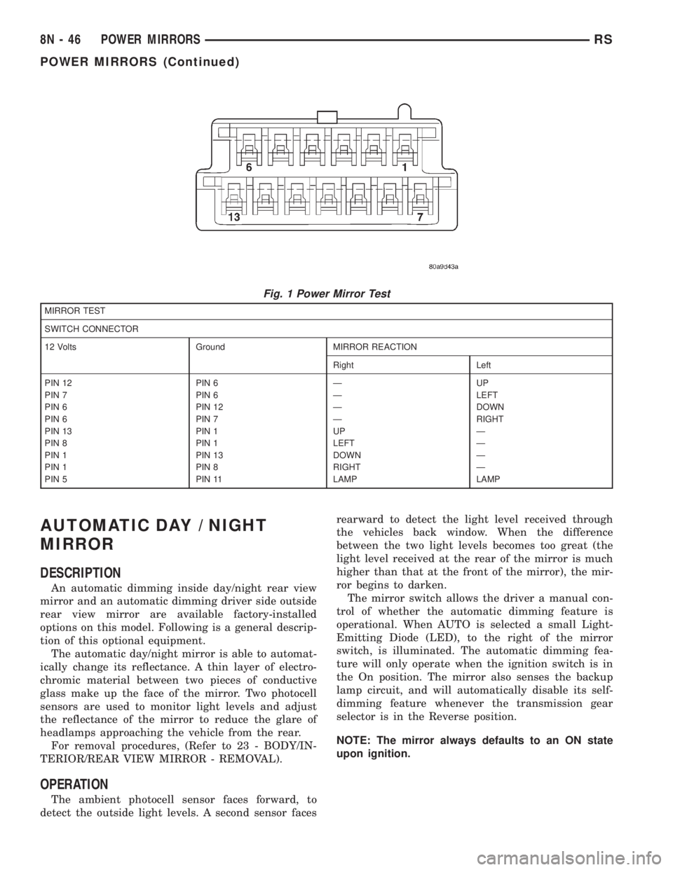
²Refer to the Mirror Test Chart for wire hookups
at the switch connector (Fig. 1).
(4) If results shown in table are not obtained,
check for broken or shorted circuit, or replace mirror
assembly as necessary.
RSPOWER MIRRORS8N-45
Page 2026 of 4284
AUTOMATIC DAY / NIGHT
MIRROR
DESCRIPTION
An automatic dimming inside day/night rear view
mirror and an automatic dimming driver side outside
rear view mirror are available factory-installed
options on this model. Following is a general descrip-
tion of this optional equipment.
The automatic day/night mirror is able to automat-
ically change its reflectance. A thin layer of electro-
chromic material between two pieces of conductive
glass make up the face of the mirror. Two photocell
sensors are used to monitor light levels and adjust
the reflectance of the mirror to reduce the glare of
headlamps approaching the vehicle from the rear.
For removal procedures, (Refer to 23 - BODY/IN-
TERIOR/REAR VIEW MIRROR - REMOVAL).
OPERATION
The ambient photocell sensor faces forward, to
detect the outside light levels. A second sensor facesrearward to detect the light level received through
the vehicles back window. When the difference
between the two light levels becomes too great (the
light level received at the rear of the mirror is much
higher than that at the front of the mirror), the mir-
ror begins to darken.
The mirror switch allows the driver a manual con-
trol of whether the automatic dimming feature is
operational. When AUTO is selected a small Light-
Emitting Diode (LED), to the right of the mirror
switch, is illuminated. The automatic dimming fea-
ture will only operate when the ignition switch is in
the On position. The mirror also senses the backup
lamp circuit, and will automatically disable its self-
dimming feature whenever the transmission gear
selector is in the Reverse position.
NOTE: The mirror always defaults to an ON state
upon ignition.
Fig. 1 Power Mirror Test
MIRROR TEST
SWITCH CONNECTOR
12 Volts Ground MIRROR REACTION
Right Left
PIN 12 PIN 6 Ð UP
PIN 7 PIN 6 Ð LEFT
PIN 6 PIN 12 Ð DOWN
PIN 6 PIN 7 Ð RIGHT
PIN 13 PIN 1 UP Ð
PIN 8 PIN 1 LEFT Ð
PIN 1 PIN 13 DOWN Ð
PIN 1 PIN 8 RIGHT Ð
PIN 5 PIN 11 LAMP LAMP
8N - 46 POWER MIRRORSRS
POWER MIRRORS (Continued)
Page 2028 of 4284
REMOTE SWITCH
DIAGNOSIS AND TESTING - REMOTE SWITCH
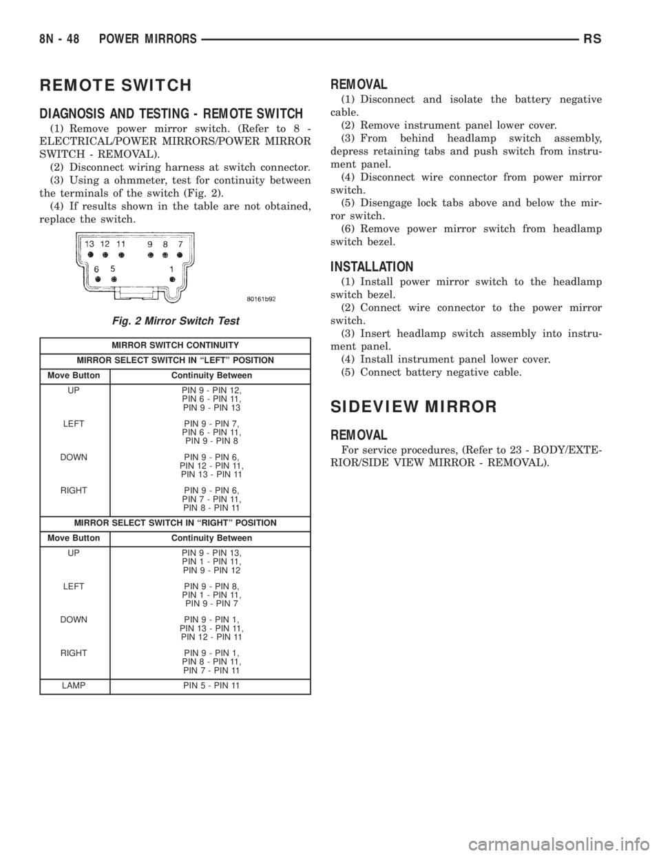
(1) Remove power mirror switch. (Refer to 8 -
ELECTRICAL/POWER MIRRORS/POWER MIRROR
SWITCH - REMOVAL).
(2) Disconnect wiring harness at switch connector.
(3) Using a ohmmeter, test for continuity between
the terminals of the switch (Fig. 2).
(4) If results shown in the table are not obtained,
replace the switch.
REMOVAL
(1) Disconnect and isolate the battery negative
cable.
(2) Remove instrument panel lower cover.
(3) From behind headlamp switch assembly,
depress retaining tabs and push switch from instru-
ment panel.
(4) Disconnect wire connector from power mirror
switch.
(5) Disengage lock tabs above and below the mir-
ror switch.
(6) Remove power mirror switch from headlamp
switch bezel.
INSTALLATION
(1) Install power mirror switch to the headlamp
switch bezel.
(2) Connect wire connector to the power mirror
switch.
(3) Insert headlamp switch assembly into instru-
ment panel.
(4) Install instrument panel lower cover.
(5) Connect battery negative cable.
SIDEVIEW MIRROR
REMOVAL
For service procedures, (Refer to 23 - BODY/EXTE-
RIOR/SIDE VIEW MIRROR - REMOVAL).
Fig. 2 Mirror Switch Test
MIRROR SWITCH CONTINUITY
MIRROR SELECT SWITCH IN ªLEFTº POSITION
Move Button Continuity Between
UP PIN 9 - PIN 12,
PIN 6 - PIN 11,
PIN 9 - PIN 13
LEFT PIN 9 - PIN 7,
PIN 6 - PIN 11,
PIN 9 - PIN 8
DOWN PIN 9 - PIN 6,
PIN 12 - PIN 11,
PIN 13 - PIN 11
RIGHT PIN 9 - PIN 6,
PIN 7 - PIN 11,
PIN 8 - PIN 11
MIRROR SELECT SWITCH IN ªRIGHTº POSITION
Move Button Continuity Between
UP PIN 9 - PIN 13,
PIN 1 - PIN 11,
PIN 9 - PIN 12
LEFT PIN 9 - PIN 8,
PIN 1 - PIN 11,
PIN 9 - PIN 7
DOWN PIN 9 - PIN 1,
PIN 13 - PIN 11,
PIN 12 - PIN 11
RIGHT PIN 9 - PIN 1,
PIN 8 - PIN 11,
PIN 7 - PIN 11
LAMP PIN5-PIN11
8N - 48 POWER MIRRORSRS
Page 2069 of 4284
VEHICLE THEFT SECURITY
TABLE OF CONTENTS
page page
VEHICLE THEFT SECURITY
DESCRIPTION............................1
OPERATION.............................1
DIAGNOSIS AND TESTING..................2
SENTRY KEY IMMOBILIZER SYSTEM........2
VEHICLE THEFT SECURITY SYSTEM........3
HOOD AJAR SWITCH
REMOVAL...............................3
INSTALLATION............................3TRANSPONDER KEY
DESCRIPTION............................3
OPERATION.............................4
STANDARD PROCEDURE...................4
TRANSPONDER PROGRAMMING...........4
VTSS/SKIS INDICATOR LAMP
DESCRIPTION............................5
OPERATION.............................5
VEHICLE THEFT SECURITY
DESCRIPTION
VEHICLE THEFT SECURITY SYSTEM
The Vehicle Theft Security System (VTSS) is
designed to protect against whole vehicle theft. The
system monitors vehicle doors, hood, liftgate, and
ignition action for unauthorized operation. The alarm
activates:
²Sounding of the horn
²Flashing of the park and tail lamps
²Flashing of the headlamps
²An engine kill feature (without SKIS)
SENTRY KEY IMMOBILIZER SYSTEM
The Sentry Key Immobilizer System (SKIS) is
available as a factory-installed option on this vehicle.
It is designed to provide passive protection against
unauthorized vehicle use by disabling the engine,
after two (2) seconds of running, whenever an invalid
key is used to start the vehicle. The SKIS is active
whenever the ignition is on and does not require any
customer intervention. The primary components of
the system are the Sentry Key Immobilizer Module
(SKIM), Sentry Key (ignition key w/ a transponder
molded into the head), indicator light, Body Control
Module (BCM), and the Powertrain Control Module
(PCM). The SKIM is mounted to the steering column
with the molded, integral antenna mounted on the
light halo surrounding the ignition lock cylinder. The
indicator light, is located in the message center.
OPERATION
VEHICLE THEFT SECURITY SYSTEM
Upon failure of proper SKIM communication to the
PCM, the PCM will shut off fuel after two seconds ofrun time. The engine will not re-crank on the key
cycle that the failure occurred, a full key down
sequence must be performed for the engine to crank
again. After six consecutive fuel shut-offs, the engine
will no longer crank on subsequent key cycles. The
failure must be corrected and a valid communication
process between the SKIM and the PCM must occur
for the engine to crank and start again.
The electronics for the VTSS are part of the Body
Control Module (BCM). The system is armed when
the vehicle is locked using the:
²Power door lock switches (with any door ajar)
²Remote Keyless Entry transmitter.
²Door Cylinder Lock Switches.
For vehicles equipped with SKIS, the doors do not
have to be locked to enable the fuel shut off feature.
After the vehicle is locked and the last door is
closed, the set LED indicator in the top cover will
flash quickly for 16 seconds, indicating that arming
is in progress. If no monitored systems are activated
during this period, the system will arm. The LED
will extinguish unless the liftgate is open. If the lift-
gate is open, the LED will flash at a slower rate.
This indicates that the system is armed. If fault is
detected on any key cylinder input, the indicator
LED will remain solid during the arming process,
although the system will still arm. If the indicator
LED does not illuminate at all upon door closing it
indicates that the system is not arming.
Passive disarming occurs upon normal vehicle
entry by unlocking either door with the ignition key/
remote transmitter. This disarming will also halt the
alarm once it has been activated.
A tamper alert exists to notify the driver that the
VTSS had been activated. This alert consists of 3
horn pulses when the vehicle is disarmed.
RSVEHICLE THEFT SECURITY8Q-1
Page 2099 of 4284
8W-02 COMPONENT INDEX
Component Page
A/C Compressor Clutch Relay........... 8Wa-42
A/C Compressor Clutch................ 8Wa-42
A/C-Heater Control................... 8Wa-42
A/C Pressure Sensor.................. 8Wa-42
Accelerator Pedal Position Sensor........ 8Wa-30
Accessory Relay...................... 8Wa-10
Airbags............................. 8Wa-43
Ambient Temp Sensor................. 8Wa-49
Antenna............................ 8Wa-47
ATC Remote Sensor................... 8Wa-42
Auto Shut Down Relay................. 8Wa-30
Auto Temp Control.................... 8Wa-42
Automatic Day/Night Mirror............ 8Wa-49
Autostick Switch..................... 8Wa-31
Back-Up Lamp Switch................. 8Wa-51
Battery Temperature Sensor............ 8Wa-20
Battery............................. 8Wa-20
Blend Door Actuators.................. 8Wa-42
Blower Motor Resistor................. 8Wa-42
Body Control Module.................. 8Wa-45
Boost Pressure Sensor................. 8Wa-30
B-Pillar Switches..................... 8Wa-61
Brake Fluid Level Switch............... 8Wa-40
Brake Lamp Switch................... 8Wa-51
Brake Transmission Shift Interlock
Solenoid.......................... 8Wa-31
Cabin Heater Assist................... 8Wa-30
Camshaft Position Sensor.............. 8Wa-30
CD Changer......................... 8Wa-47
Center High Mounted Stop Lamp........ 8Wa-51
Cinch/Release Motors.................. 8Wa-61
Clockspring................. 8Wa-33, 41, 43, 47
Clutch Pedal Interlock Switch Jumper..... 8Wa-10
Clutch Pedal Interlock Switch........... 8Wa-10
Clutch Pedal Upstop Switch............. 8Wa-30
Combination Relays................... 8Wa-54
Controller Antilock Brake.............. 8Wa-35
Crank Case Ventilation Heater.......... 8Wa-30
Crankshaft Position Sensor............. 8Wa-30
Cylinder Lock Switches................ 8Wa-39
Data Link Connector.................. 8Wa-18
Defogger Relay....................... 8Wa-48
Diagnostic Junction Port............... 8Wa-18
Dome Lamps........................ 8Wa-44
Door Ajar Switches.................... 8Wa-39
Door Courtesy Lamps.................. 8Wa-44
Door Lock Motor/Ajar Switches.......... 8Wa-61
Door Lock Switches................... 8Wa-61
Dosing Pump........................ 8Wa-30
Driver Heated Seat Module............. 8Wa-63
ECM/PCM Relay..................... 8Wa-30
EGR Solenoid........................ 8Wa-30Component Page
Electric Wiper De-Icer................. 8Wa-48
Engine Control Module................ 8Wa-30
Engine Coolant Temp Sensor............ 8Wa-30
Engine Oil Pressure Sensor............. 8Wa-30
Engine Oil Pressure Switch............. 8Wa-30
Engine Oil Temperature Sensor.......... 8Wa-30
EVAP/Purge Solenoid.................. 8Wa-30
Evaporator Temperature Sensor......... 8Wa-42
Floor Console Lamp................... 8Wa-44
Floor Console Power Outlet............. 8Wa-41
Fog Lamps.......................... 8Wa-50
Front Blower Module.................. 8Wa-42
Front Blower Motor Relay.............. 8Wa-42
Front Blower Motor................... 8Wa-42
Front Cigar Lighter................... 8Wa-41
Front Control Module.................. 8Wa-10
Front Fog Lamp Relay................. 8Wa-50
Front Intrusion Sensor................. 8Wa-39
Front Reading Lamps/Switch............ 8Wa-44
Front Washer Pump Motor.............. 8Wa-53
Front Wiper Hi/Low Relay.............. 8Wa-53
Front Wiper On/Off Relay.............. 8Wa-53
Fuel Heater Relay.................... 8Wa-10
Fuel Heater......................... 8Wa-30
Fuel Injectors........................ 8Wa-30
Fuel Pressure Sensor.................. 8Wa-30
Fuel Pressure Solenoid................. 8Wa-30
Fuel Pump Module.................... 8Wa-30
Fuel Pump Relay..................... 8Wa-30
Full Open Switches................... 8Wa-61
Fuselink............................ 8Wa-10
Fuses (IPM)......................... 8Wa-10
Generator........................... 8Wa-20
Glove Box Lamp...................... 8Wa-44
Glow Plug Relay...................... 8Wa-30
Glow Plugs.......................... 8Wa-30
Grounds............................ 8Wa-15
Halo Lamp.......................... 8Wa-44
Headlamp Leveling Motors............. 8Wa-50
Headlamp Switch..................... 8Wa-50
Headlamp Washer Pump Motor.......... 8Wa-53
Headlamp Washer Relay............... 8Wa-53
Headlamps.......................... 8Wa-50
Heated Seat Backs.................... 8Wa-63
Heated Seat Cushions................. 8Wa-63
High Beam Lamps.................... 8Wa-50
Hood Ajar Switch..................... 8Wa-39
Horn Relay.......................... 8Wa-41
Horn Switch......................... 8Wa-41
Horns.............................. 8Wa-41
Idle Air Control Motor................. 8Wa-30
Ignition Coil......................... 8Wa-30
RG8W-02 COMPONENT INDEX8Wa-02-1
Page 2103 of 4284
8W-10 POWER DISTRIBUTION
Component PageA/C Compressor Clutch..................8Wa-10-19, 20, 38, 40
A/C Compressor Clutch Relay.............8Wa-10-19, 20, 37, 38, 40
Accessory Relay.......................8Wa-10-15, 26, 57
Ambient Temp Sensor........................8Wa-10-54
Auto Shut Down Relay......................8Wa-10-19, 34
Auto Temp Control.........................8Wa-10-33
Back-Up Lamp Switch........................8Wa-10-58
Battery........................8Wa-10-12, 13, 14, 34, 40
Blower Motor Resistor......................8Wa-10-17, 31
Body Control Module......8Wa-10-21, 33, 38, 41, 42, 44, 46, 47, 48, 49, 61
Brake Fluid Level Switch......................8Wa-10-57
Brake Lamp Switch.....................8Wa-10-21, 44, 59
Brake Transmission Shift Interlock Solenoid.............8Wa-10-55
Cabin Heater Assist.....................8Wa-10-20, 36, 52
Camshaft Position Sensor......................8Wa-10-37
Center High Mounted Stop Lamp..................8Wa-10-59
Clockspring.............................8Wa-10-53
Clutch Pedal Interlock Switch Jumper........8Wa-10-16, 30, 46, 47, 53
Clutch Pedal Interlock Switch............8Wa-10-16, 30, 46, 47, 53
Controller Antilock Brake...........8Wa-10-16, 21, 30, 42, 48, 54, 59
Crank Case Ventilation Heater...................8Wa-10-41
Data Link Connector.......................8Wa-10-29, 61
Defogger Relay......................8Wa-10-17, 18, 32, 56
Diagnostic Junction Port.......................8Wa-10-54
Driver Door Lock Switch.....................8Wa-10-28, 29
Driver Heated Seat Module.....................8Wa-10-42
Driver Power Seat Switch......................8Wa-10-42
Driver Power Window Switch....................8Wa-10-29
ECM/PCM Relay.........................8Wa-10-20, 36
EGR Solenoid..........................8Wa-10-37, 39
Electric Wiper De-Icer........................8Wa-10-28
Engine Control Module........8Wa-10-16, 20, 30, 36, 37, 40, 41, 58, 59
Floor Console Lamp.........................8Wa-10-27
Floor Console Power Outlet...................8Wa-10-27, 29
Front Blower Module......................8Wa-10-17, 31
Front Blower Motor Relay................8Wa-10-16, 17, 31, 56
Front Cigar Lighter.......................8Wa-10-15, 27
Front Control Module . . . 8Wa-10-14, 15, 16, 17, 18, 19, 20, 21, 22, 23, 24, 25,
26, 29, 30, 31, 32, 38, 40, 45, 46, 47, 50, 51, 52, 53, 54. 55, 56, 57, 58, 59, 61
Front Fog Lamp Relay....................8Wa-10-14, 22, 56
Front Washer Pump Motor..................8Wa-10-15, 26, 61
Front Wiper Hi/Low Relay..................8Wa-10-15, 25, 57
Front Wiper On/Off Relay..................8Wa-10-15, 25, 52
Fuel Heater.............................8Wa-10-41
Fuel Heater Relay......................8Wa-10-20, 40, 57
Fuel Injector No. 1..........................8Wa-10-35
Fuel Injector No. 2..........................8Wa-10-35
Fuel Injector No. 3..........................8Wa-10-35
Fuel Injector No. 4..........................8Wa-10-35
Fuel Injector No. 5..........................8Wa-10-35
Fuel Injector No. 6..........................8Wa-10-35
Fuel Pressure Solenoid.......................8Wa-10-37
Fuel Pump Module........................8Wa-10-19, 38
Fuel Pump Relay.......................8Wa-10-19, 38, 57
Fuse 1 (IPM).........................8Wa-10-14, 15, 22
Fuse 2 (IPM) (Diesel).....................8Wa-10-14, 10-24
Fuse 2 (IPM) (Gas)......................8Wa-10-14, 10-23
Fuse 3 (IPM).........................8Wa-10-14, 23, 24
Fuse 4 (IPM).......................8Wa-10-14, 15, 16, 25
Fuse 5 (IPM)...........................8Wa-10-15, 26
Fuse 6 (IPM)...........................8Wa-10-15, 26
Fuse 8 (IPM)...........................8Wa-10-16, 29
Fuse 9 (IPM).........................8Wa-10-16, 17, 30
Fuse 10 (IPM)..........................8Wa-10-17, 31
Fuse 11 (IPM)..........................8Wa-10-15, 26
Fuse 12 (IPM)..........................8Wa-10-17, 31
Fuse 13 (IPM)..........................8Wa-10-18, 32
Fuse 14 (IPM)....................8Wa-10-18, 19, 20, 32, 52
Fuse 15 (IPM) (Diesel)......................8Wa-10-20, 36
Fuse 15 (IPM) (Gas).....................8Wa-10-18, 19, 34
Fuse 16 (IPM) (Diesel)......................8Wa-10-20, 36
Fuse 16 (IPM) (Gas).......................8Wa-10-19, 34
Fuse 17 (IPM) (Diesel)......................8Wa-10-20, 40
Fuse 17 (IPM) (Gas).......................8Wa-10-19, 38
Fuse 18 (IPM)....................8Wa-10-19, 20, 21, 38, 40
Fuse 19 (IPM)......................8Wa-10-19, 20, 21, 42
Fuse 20 (IPM)..........................8Wa-10-21, 42
Fuse 21 (IPM)..........................8Wa-10-21, 42
Fuse 22 (IPM)..........................8Wa-10-21, 42
Fuse 23 (IPM)........................8Wa-10-21, 46, 47
Fuse 24 (IPM)............................8Wa-10-21
Fuse 24 (IPM)............................8Wa-10-44
Fuse 26 (IPM)..........................8Wa-10-21, 44
Fuse 27 (IPM)..........................8Wa-10-21, 44
Fuse 28 (IPM)..........................8Wa-10-15, 26
Fuse 30 (IPM)..........................8Wa-10-21, 45
Fuse 31 (IPM)..........................8Wa-10-21, 45
Fuse 32 (IPM)..........................8Wa-10-21, 45
Fuse 33 (IPM)............................8Wa-10-15
Fuse 33 (IPM)............................8Wa-10-26
Fuselink.............................8Wa-10-12, 13
G100................................8Wa-10-48
G101...............................8Wa-10-34, 40
G103................................8Wa-10-61
G300................................8Wa-10-50
G300................................8Wa-10-51
Generator........................8Wa-10-12, 13, 35, 37
Glow Plug Relay.........................8Wa-10-12, 37
Headlamp Switch........................8Wa-10-24, 55Component PageHeadlamp Washer Pump Motor.................8Wa-10-21, 45
Headlamp Washer Relay...................8Wa-10-21, 45, 56
High Note Horn...........................8Wa-10-29
Horn Relay..........................8Wa-10-16, 29, 52
Ignition Coil.............................8Wa-10-35
Ignition Switch............8Wa-10-16, 21, 30, 38, 39, 41, 46, 47, 53
Instrument Cluster.......................8Wa-10-21, 44
Intelligent Power Module . . 8Wa-10-2, 10-3, 10-4, 10-12, 14, 15, 16, 17, 18, 19,
20, 21, 22, 23, 24, 25, 26, 27, 28, 29, 30, 31, 32, 33, 34, 35, 36, 37, 38, 39, 40,
41, 42, 44, 45, 46, 47, 48, 49, 50, 51, 52, 53, 54, 55, 56, 57, 58, 59, 61
Leak Detection Pump........................8Wa-10-39
Left B-Pillar Switch.........................8Wa-10-28
Left Combination Relay.......................8Wa-10-60
Left Fog Lamp..........................8Wa-10-14, 22
Left Front Park/ Turn Signal Lamp............8Wa-10-14, 23, 49, 58
Left Headlamp............................8Wa-10-50
Left Headlamp Leveling Motor................8Wa-10-24, 55, 58
Left High Beam Lamp........................8Wa-10-51
Left Low Beam Lamp........................8Wa-10-51
Left Park Lamp.........................8Wa-10-24, 58
Left Power Mirror..........................8Wa-10-32
Left Rear Lamp Assembly..............8Wa-10-23, 24, 58, 59, 60
Left Repeater Lamp.........................8Wa-10-44
Left Side Impact Airbag Control Module...............8Wa-10-55
Left Sliding Door Control Module..................8Wa-10-45
Left Stop/ Turn Signal Relay.....................8Wa-10-60
Left Turn Signal Lamp.......................8Wa-10-49
License Lamp........................8Wa-10-23, 24, 58
Lift Pump Motor.........................8Wa-10-20, 36
Lift Pump Relay.........................8Wa-10-20, 36
Low Note Horn...........................8Wa-10-29
Mass Air Flow Sensor........................8Wa-10-37
Memory Seat/ Mirror Module....................8Wa-10-42
Message Center...........................8Wa-10-44
Name Brand Speaker Relay.................8Wa-10-18, 32, 52
Occupant Restraint Controller..................8Wa-10-56, 61
Overhead Console..........................8Wa-10-33
Oxygen Sensor 1/1 Upstream....................8Wa-10-35
Oxygen Sensor 1/2 Downstream...................8Wa-10-35
Park Lamp Relay.....................8Wa-10-14, 23, 24, 52
Park/ Neutral Position Switch....................8Wa-10-58
Passenger Door Lock Switch...................8Wa-10-26, 28
Passenger Folding Mirror Relay.............8Wa-10-19, 20, 38, 40
Passenger Heated Seat Module...................8Wa-10-43
Passenger Power Seat Switch....................8Wa-10-43
Passenger Power Window Switch..................8Wa-10-26
Power Liftgate Module......................8Wa-10-21, 45
Power Mirror Switch...................8Wa-10-19, 20, 39, 40
Power Outlet............................8Wa-10-29
Power Seat Circuit Breaker...................8Wa-10-21, 42
Power Window Circuit Breaker.................8Wa-10-15, 26
Powertrain Control Module........8Wa-10-16, 19, 30, 34, 35, 38, 39, 48
PTC4 ..............................8Wa-10-18, 32
Ptc7.............................8Wa-10-15, 16, 29
Radiator Fan Relay.....................8Wa-10-21, 44, 48
Radiator Fan Relay No. 1....................8Wa-10-12, 37
Radiator Fan Relay No. 2....................8Wa-10-37, 44
Radiator Fan Relay No. 3....................8Wa-10-21, 37
Radio..............................8Wa-10-27, 33
Radio Choke...........................8Wa-10-18, 32
Rear A/C-Heater Unit......................8Wa-10-17, 31
Rear Blower Motor Power Module..................8Wa-10-31
Rear Blower Motor Relay.................8Wa-10-17, 18, 31, 56
Rear Power Outlet......................8Wa-10-15, 26, 27
Rear Washer Pump Motor..................8Wa-10-15, 26, 61
Rear Window Defogger Grid...................8Wa-10-18, 32
Rear Wiper Motor..........................8Wa-10-28
Remote Keyless Entry Module....................8Wa-10-33
Right B-Pillar Switch........................8Wa-10-28
Right Combination Relay......................8Wa-10-60
Right Fog Lamp.........................8Wa-10-14, 22
Right Front Park/ Turn Signal Lamp...........8Wa-10-14, 23, 49, 53
Right Headlamp...........................8Wa-10-50
Right Headlamp Leveling Motor...............8Wa-10-24, 53, 55
Right High Beam Lamp.......................8Wa-10-51
Right Low Beam Lamp.......................8Wa-10-51
Right Park Lamp........................8Wa-10-24, 53
Right Power Mirror.........................8Wa-10-32
Right Rear Lamp Assembly................8Wa-10-14, 23, 24, 59
Right Repeater Lamp........................8Wa-10-44
Right Side Impact Airbag Control Module..............8Wa-10-55
Right Sliding Door Control Module.................8Wa-10-45
Right Stop/ Turn Signal Relay....................8Wa-10-60
Right Turn Signal Lamp.......................8Wa-10-49
Sentry Key Immobilizer Module...........8Wa-10-33, 39, 41, 46, 47
Solenoid/ Pressure Switch Assy...................8Wa-10-34
Starter Motor.......................8Wa-10-12, 13, 16, 30
Starter Motor Relay...................8Wa-10-16, 30, 46, 47
Thatcham Alarm Module.................8Wa-10-39, 41, 47, 61
Torque Converter Clutch Solenoid..................8Wa-10-39
Trailer Tow Connector......................8Wa-10-23, 58
Transmission Control Module...........8Wa-10-16, 19, 30, 34, 54, 55
Transmission Control Relay...................8Wa-10-19, 34
Transmission Range Sensor.....................8Wa-10-58
TXV Solenoid............................8Wa-10-31
Vehicle Speed Sensor........................8Wa-10-36
Washer Fluid Level Switch.....................8Wa-10-53
Wiper Module........................8Wa-10-15, 25, 52
RG8W-10 POWER DISTRIBUTION8Wa-10-1