Page 2140 of 4770

BE0AJ±03
Z18937
Connector ºAº Connector ºBº Connector ºCº
Connector ºAº
Connector ºBº
Connector ºCº
J±13±1±A J±16±1 J±13±1
1 2 3 4 5 6 7 8 9 10 11 12 1314 15 16 1 234 56 78 910111213 1 23456 78910111213
C7
C5
A2 B3
A1
C8
B15
C6
B6
A4
C4
B5
C10 B14
A13
B2
C1
B1
C9
A6
A11
A7
A10
A8
A9
C13
B8
B11
B12A5
C11
B4
B16 C2
A12
A3
B7
C3
C12
B9
B10
B13 F
E
T
S
ODOMETER
Fuel Level Warning
Seat Belt Warning
ABS Warning
Low Oil Pressure Warning
Cruise Control Indicator
Malfunction Indicator
O/D OFF Indicator
Light Failure Warning
Brake Warning
SLIP Indicator
TRAC Indicator
Washer Level Warning
Discharge Warning
Right Turn Indicator
Left Turn Indicator
Security Indicator
L
2
D
N
R
P
Illumination
Hi±Beam Indicator
Open Door Warning
SRS Warning
: Fuel Gauge
: Engine Coolant Temperature Gauge
: Tachometer
: Speedometer
No.
A
B
C1
2
3
4
5
6
7 8
9
10
11
12 13
14
15
16
2 3
4
5
6
7 8
9
10
11 12
131
2
3
4 5
6
7
8
9
10
11
12
13
F
E
T
SEngine coolant temperature sender gauge
Ground
Light failure sensor
Integration relay
Traction ECU
Park/neutral position switch (A/T)
O/D OFF switch (A/T)
IGN fuse
Turn signal switch
ST relay
Fuel sender gauge
Generator
Oil pressure switch
Fuel sender gauge
Parking brake switch and brake fluid level warning switch
Headlight dimmer switch
Headlight dimmer switch
Door courtesy switch
DOME fuse
ECU±B fuse
Airbag sensor assembly
ECM
No.1 Vehicle speed sensor Ground
Turn signal switch ECM
Traction ECU
ABS ECU
Ground No.1 Vehicle speed sensor
GAUGE fuse
Igniter
Security ECU
Cruise control ECU
Washer fluid level warning switch
Light control rheostat
TAIL fuse Park/neutral position switch (A/T) Park/neutral position switch (A/T) Park/neutral position switch (A/T) Park/neutral position switch (A/T)
Park/neutral position switch (A/T)Wire Harness Side
Bulb Check
Relay
N20107 N201081
BE±46
± BODY ELECTRICALCOMBINATION METER
2266 Author�: Date�:
CIRCUIT
Page 2143 of 4770

N20161
F
1/2
E1
2 3
Z05730 1
3
42
5
BE1217 Ie±5±1±A
BatteryWarning Light
Ignition
Switch
N20213
1 3
N20214
1
3
N20215
Engine coolant temperature gauge
Ignition
Switch
BatterySender
Gauge
± BODY ELECTRICALCOMBINATION METER
BE±49
2269 Author�: Date�:
6. INSPECT FUEL SENDER GAUGE RESISTANCE
Measure the resistance between terminals 2 and 3 for each
float position.
Float position mm (in.)Resistance (W)
F: Approx. ±91.1 (±3.587)Approx. 3.0
1/2: Approx. ±34.2 (±1.346)Approx. 31.7
E: Approx. 30.8 (1.213)Approx. 110.0
If resistance value is not as specified, replace the sender
gauge.
7. INSPECT FUEL LEVEL WARNING LIGHT
(a) Disconnect the connector from the sender gauge.
(b) Connect terminals 1 and 3 on the wire harness side con-
nector.
(c) Turn the ignition switch ON, check that the warning light
lights up.
If the warning light does not light up, test the bulb or inspect wire
harness.
8. INSPECT FUEL LEVEL WARNING SWITCH
(a) Apply battery positive voltage between terminals 1 and 3
through a 3.4±W test bulb, check that the bulb lights up.
HINT:
It takes a short time for the bulb to light up.
(b) Submerge the switch in fuel, check that the bulb goes out.
If operation is not as specified, replace the sender gauge.
9. INSPECT ENGINE COOLANT TEMPERATURE RE-
CEIVER GAUGE OPERATION
(a) Disconnect the connector from the sender gauge.
(b) Turn the ignition switch ON and check that the receiver
gauge needle indicates COOL.
Page 2144 of 4770

N20216
C
B
A
N21646
Z14205
Warning Light
Ignition
Switch
Battery
1 BE±50
± BODY ELECTRICALCOMBINATIO")
Z15788
Engine coolant temperature gauge
Ignition
Switch
BatteryWire Harness SideTest Bulb
(3.4 W)
N20216
C
B
A
N21646
Z14205
Warning Light
Ignition
Switch
Battery
1 BE±50
± BODY ELECTRICALCOMBINATION METER
2270 Author�: Date�:
(c) Ground terminal on the wire harness side connector
through a 3.4±W test bulb.
(d) Turn the ignition switch ON, and check that the bulb lights
up and the receiver gauge needle moves to the hot side.
If operation is as specified, replace the sender gauge.
Then, recheck the system.
If operation is not as specified, measure the receiver gauge re-
sistance.
10. INSPECT ENGINE COOLANT TEMPERATURE RE-
CEIVER GAUGE RESISTANCE
Measure the resistance between terminals.
Tester connectionResistance (W) *
A ± BApprox. 175.7
A ± CApprox. 54.0
B ± CApprox. 229.7
*: This circuit includes the diode.
HINT:
Connect the test leads so that the current from the ohmmeter
can flow according to the above order.
If resistance value is not as specified, replace the receiver
gauge.
11. INSPECT ENGINE COOLANT TEMPERATURE SEND-
ER GAUGE RESISTANCE
Measure the resistance between the terminal and gauge body.
Temperature °C (°F)Resistance (W)
50 (122.0)274
120 (248.0)26.4
If resistance value is not as specified, replace the engine cool-
ant temperature sender gauge.
12. INSPECT LOW OIL PRESSURE WARNING LIGHT
(a) Disconnect the connector from the warning switch and
ground terminal on the wire harness side connector.
(b) Turn the ignition switch ON and check that the warning
light lights up.
If the warning light does not light up, test the bulb.
Page 2372 of 4770

(+) (+)
(±)
Battery Ammeter CO±24
± COOLING (5S±FE)ELECTRIC COOLING FAN
1598 Author�: Date�:
ELECTRIC COOLING FAN")
S05959
CO06N±03
S05953
ECT Switch
Connector
Z19282
No.1
No.2Battery
Ammeter (±)
(+) (+)
(±)
Battery Ammeter CO±24
± COOLING (5S±FE)ELECTRIC COOLING FAN
1598 Author�: Date�:
ELECTRIC COOLING FAN
ON±VEHICLE INSPECTION
1. CHECK COOLING FAN OPERATION WITH LOW TEM-
PERATURE (Below 83°C (181°F))
(a) Turn the ignition switch ON.
(b) Check that the cooling fan stops.
If not, check the cooling fan relay and ECT switch, and check
for a separated connector or severed wire between the cooling
fan relay and ECT switch.
(c) Disconnect the ECT switch connector.
(d) Check that the cooling fan rotates.
If not, check the fan main relay, cooling fan relay, cooling fan,
fuses, and check for short circuit between the cooling fan relay
and ECT switch.
(e) Reconnect the ECT switch connector.
2. CHECK COOLING FAN OPERATION WITH HIGH TEM-
PERATURE (Above 93°C (199°F))
(a) Start the engine, and raise coolant temperature to above
93°C (199°F).
(b) Check that the cooling fan rotates.
If not, replace the ECT switch.
3. INSPECT COOLING FANS
(a) Disconnect the cooling fan connector.
(b) Connect battery and ammeter to the connector.
(c) Check that the cooling fan rotates smoothly, and check
the reading on the ammeter.
Standard amperage: 4.9 ± 8.5 A
(d) Reconnect the cooling fan connector.
Page 2379 of 4770
CO06T±03
S05245
ECT Switch Connector
O±RingECT
Switch
P05962
Ohmmeter
± COOLING (5S±FE)ENGINE COOLANT TEMPERATURE (ECT) SWITCH
CO±31
1605 Author�: Date�:
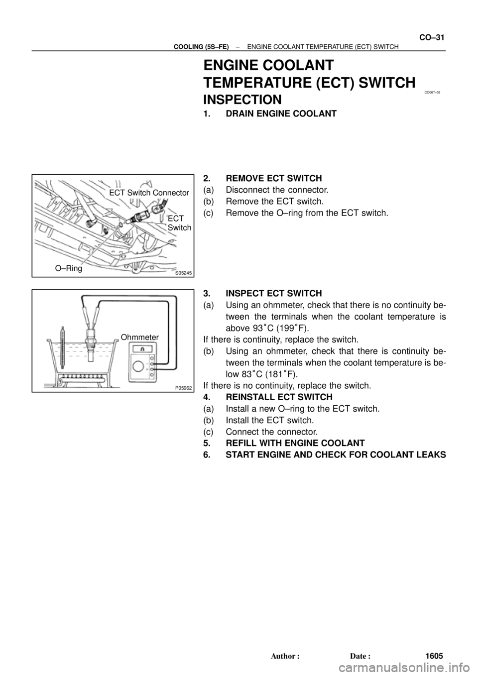
ENGINE COOLANT
TEMPERATURE (ECT) SWITCH
INSPECTION
1. DRAIN ENGINE COOLANT
2. REMOVE ECT SWITCH
(a) Disconnect the connector.
(b) Remove the ECT switch.
(c) Remove the O±ring from the ECT switch.
3. INSPECT ECT SWITCH
(a) Using an ohmmeter, check that there is no continuity be-
tween the terminals when the coolant temperature is
above 93°C (199°F).
If there is continuity, replace the switch.
(b) Using an ohmmeter, check that there is continuity be-
tween the terminals when the coolant temperature is be-
low 83°C (181°F).
If there is no continuity, replace the switch.
4. REINSTALL ECT SWITCH
(a) Install a new O±ring to the ECT switch.
(b) Install the ECT switch.
(c) Connect the connector.
5. REFILL WITH ENGINE COOLANT
6. START ENGINE AND CHECK FOR COOLANT LEAKS
Page 2407 of 4770
ELECTRIC COOLING FAN
CO±25
1633 Author�: Date�:
ELECTRIC COOLING FAN
ON±VEHICLE INSPECTION
1. CHECK COOLING FAN O")
B05939
CO03S±03
S04727
Disconnect
B05940
B05941
Ammeter
Battery
± COOLING (1MZ±FE)ELECTRIC COOLING FAN
CO±25
1633 Author�: Date�:
ELECTRIC COOLING FAN
ON±VEHICLE INSPECTION
1. CHECK COOLING FAN OPERATION WITH LOW
TEMPERATURE (Below 88°C (190°F))
(a) Turn the ignition switch ON.
(b) Check that the cooling fan stops.
If not, check the cooling fan relay and ECT switch, and check
for a separated connector or severed wire between the cooling
fan relay and ECT switch.
(c) Disconnect the No.1 ECT switch connector.
(d) Check that the cooling fan rotates.
If not, check the fuses, engine main relay, cooling fan relay,
cooling fan, and check for a short circuit between the cooling
fan relay and ECT switch.
(e) Reconnect the No.1 ECT switch connector.
2. CHECK COOLING FAN OPERATION WITH HIGH
TEMPERATURE (Above 98°C (208°F))
(a) Start the engine, and raise coolant temperature to above
98°C (208°F).
(b) Check that the cooling fan rotates.
If not, replace the No.1 ECT switch.
3. INSPECT NO.1 COOLING FAN
(a) Disconnect the cooling fan connector.
(b) Connect battery and ammeter to the cooling fan connec-
tor.
(c) Check that the cooling fan rotates smoothly, and check
the reading on the ammeter.
Standard amperage: 8.3 ± 11.3 A at 20°C (68°F)
(d) Reconnect the cooling fan connector.
Page 2416 of 4770
ENGINE COOLANT TEMPERATURE (ECT) SWITCH
1642 Author�: Date�:
ENGINE COOLANT
TEMPERATUR")
CO03Y±04
S04602No.1 ECT Switch
P01924
Ohmmeter
S04601
No.2 ECT
Switch
P06722
Ohmmeter CO±34
± COOLING (1MZ±FE)ENGINE COOLANT TEMPERATURE (ECT) SWITCH
1642 Author�: Date�:
ENGINE COOLANT
TEMPERATURE (ECT) SWITCH
INSPECTION
1. DRAIN ENGINE COOLANT
2. INSPECT NO.1 ECT SWITCH
(a) Remove the No.1 ECT switch.
(b) Inspect the No.1 ECT switch.
(1) Using an ohmmeter, check that there is no continu-
ity between the terminals when the coolant temper-
ature is above 98°C (208°F).
If there is continuity, replace the switch.
(2) Check that there is continuity, between the termi-
nals when the coolant temperature is below 88°C
(190°F).
If there is no continuity, replace the switch.
(c) Reinstall the No.1 ECT switch.
3. INSPECT NO.2 ECT SWITCH
(a) Remove the No.2 ECT switch.
(b) Inspect the No.2 ECT switch.
(1) Using an ohmmeter, check that there is continuity
between terminals when the coolant temperature is
above 94°C (201°F).
If there is no continuity, replace the switch.
(2) Check that there is no continuity between the termi-
nals when the coolant temperature is below 83°C
(181°F).
If there is continuity, replace the switch.
(c) Reinstall the No.2 ECT switch.
Page 2417 of 4770
± COOLING (1MZ±FE)ENGINE COOLANT TEMPERATURE (ECT) SWITCH
CO±35
1643 Author�: Date�:
4. REFILL ENGINE COOLANT
5. START ENGINE AND CHECK FOR COOLANT LEAKS