Page 2424 of 4770

239 Author�: Date�: �
The diagnosis system operates in normal mode
during normal vehicle use. It also has a check mode
for technicians to simulate malfunction sympt")
DI±4
± DIAGNOSTICSENGINE (5S±FE)
239 Author�: Date�: �
The diagnosis system operates in normal mode
during normal vehicle use. It also has a check mode
for technicians to simulate malfunction symptoms
and troubleshoot. Most DTCs use 2 trip detection
logic* to prevent erroneous detection, and ensure
thorough malfunction detection. By switching the
ECM to check mode when troubleshooting, the
technician can cause the MIL to light up for a mal-
function that is only detected once or momentarily.
(TOYOTA hand±held tester only)
(See page DI±3)
�*2 trip detection logic: When a malfunction is first
detected, the malfunction is temporarily stored in
the ECM memory.(1st trip)
If the same malfunction is detected again during the second
drive test, this second detection causes the MIL to light up.(2nd
trip) (However, the IG switch must be turned OFF between the
1st trip and the 2nd trip.)
�Freeze frame data:
Freeze frame data records the engine condition
when a misfire (DTCs P0300 ~ P0304) or fuel trim
malfunction (DTCs P0171, P0172) or other mal-
function (first malfunction only), is detected.
Because freeze frame data records the engine
conditions (fuel system, calculated load, engine
coolant temperature, fuel trim, engine speed, ve-
hicle speed, etc.) when the malfunction is detected,
when troubleshooting it is useful for determining
whether the vehicle was running or stopped, the en-
gine warmed up or not, the air±fuel ratio lean or rich,
etc. at the time of the malfunction.
�Priorities for troubleshooting:
If troubleshooting priorities for multiple DTCs are given in the
applicable DTC chart, these should be followed.
If no instructions are given troubleshoot DTCs according to the
following priorities.
(1) DTCs other than fuel trim malfunction (DTCs
P0171, P0172), EGR (DTCs P0401, P0402), and
misfire (DTCs P0300 ~ P0304).
(2) Fuel trim malfunction (DTCs P0171, P0172), and
EGR (DTCs P0401, P0402).
(3) Misfire (DTCs P0300 ~ P0304).
Page 2428 of 4770

243 Author�: Date�:
4. FAIL±SAFE CHART
If any of the following codes is recorded, the ECM enters fail±safe mode.
DTC No.Fail±Safe OperationFail±Safe Deactivatio")
DI±8
± DIAGNOSTICSENGINE (5S±FE)
243 Author�: Date�:
4. FAIL±SAFE CHART
If any of the following codes is recorded, the ECM enters fail±safe mode.
DTC No.Fail±Safe OperationFail±Safe Deactivation Conditions
P0105Ignition timing fixed at 5° BTDCReturned to normal condition
P0110Intake air temperature is fixed at 20°C (68°F)Returned to normal condition
P0115Engine coolant temperature is fixed at 80°(176°F)Returned to normal condition
P0120VTA is fixed at 0°
The following condition must be repeated at least 2 times
consecutively
VTA ��0.1 V and � 0.95 V
P0135
P0141The heater circuit in witch an abnormality is detected is
turned offIgnition switch OFF
P0325Max. timing retardationIgnition switch OFF
P0336Fuel cutReturned to normal condition
P1135The heater circuit in which an abnormality is detected is
turned offIgnition switch OFF
P1300
P1310Fuel cutIGF signal is detected for 2 consecutive ignitions
5. CHECK FOR INTERMITTENT PROBLEMS
TOYOTA HAND±HELD TESTER only:
By putting the vehicle's ECM in check mode, 1 trip detection logic is possible instead of 2 trip detection logic
and sensitivity to detect open circuits is increased. This makes it easier to detect intermittent problems.
(1) Clear the DTC (See page DI±3).
(2) Set the check mode (See page DI±3).
(3) Perform a simulation test (See page IN±21).
(4) Check the connector and terminal (See page IN±31).
(5) Handle the connector (See page IN±31).
6. BASIC INSPECTION
When the malfunction code is not confirmed in the DTC check, troubleshooting should be performed in the
order for all possible circuits to be considered as the causes of the problems. In many cases, by carrying
out the basic engine check shown in the following flow chart, the location causing the problem can be found
quickly and efficiently. Therefore, use of this check is essential in engine troubleshooting.
1 Is battery positive voltage 11 V or more when engine is stopped?
NO Charge or replace battery.
YES
Page 2461 of 4770
± DIAGNOSTICSENGINE (5S±FE)
DI±41
276 Author�: Date�:
DTC P0115 Engine Coolant Temp. Circuit Malfunction
CIRCUIT DESCRIPTION
A thermistor built into the engine coolant temp. sensor changes the resistance value according to the engine
coolant temp.
The structure of the sensor and connection to the ECM is the same as in the intake air temp. circuit malfunc-
tion shown on page DI±35.
If the ECM detects the DTC P0115, it operates fail safe function in which the engine coolant temperature
is assumed to be 80°C (176°F).
DTC No.Detection ItemTrouble Area
P0115Open or short in engine coolant temp. sensor circuit
�Open or short in engine coolant temp. sensor circuit
�Engine coolant temp. sensor
�ECM
HINT:
After confirming DTC P0115, use the OBD II scan tool or TOYOTA hand±held tester to confirm the engine
coolant temp. from the CURRENT DATA.
Temp. DisplayedMalfunction
±40°C (±40°F)Open circuit
140°C (284°F) or moreShort circuit
DI00P±05
Page 2463 of 4770

DI±43
278 Author�: Date�:
1 Connect OBD II scan tool or TOYOTA hand±held tester, and read value of")
A00395
ECM ON
Engine Coolant
Temp. Sensor
2
14
9
THW
E25 V
E1 E8
E8
± DIAGNOSTICSENGINE (5S±FE)
DI±43
278 Author�: Date�:
1 Connect OBD II scan tool or TOYOTA hand±held tester, and read value of
engine coolant temperature.
PREPARATION:
(a) Connect the OBD II scan tool or TOYOTA hand±held tester to the DLC3.
(b) Turn the ignition switch ON and push the OBD II scan tool or TOYOTA hand±held tester main switch
ON.
CHECK:
Read temperature value on the OBD II scan tool or TOYOTA hand±held tester.
OK:
Same as actual engine coolant temperature
HINT:
�If there is open circuit, OBD II scan tool or TOYOTA hand±held tester indicates ±40°C (±40°F).
�If there is open circuit, OBD II scan tool or TOYOTA hand-held tester indicates 140°C (284°F) or more.
NG ±40°C (±40°F) ... Go to step 2.
140°C (284°F) or more ... Go to step 4.
OK
Check for intermittent problems
(See page DI±3).
2 Check for open in harness or ECM.
PREPARATION:
(a) Disconnect the engine coolant temp. sensor connector.
(b) Connect the sensor wire harness terminals together.
(c) Turn the ignition switch ON.
CHECK:
Read temperature value on the OBD II scan tool or TOYOTA
hand±held tester.
OK:
Temperature value: 140°C (284°F) or more
OK Confirm good connection at sensor. If OK, re-
place engine coolant temp. sensor.
NG
Page 2464 of 4770
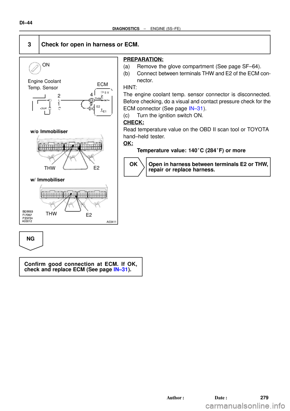
A03012A03411
ON
4 Engine Coolant
Temp. Sensor
2
1ECM
THWE2
5 V
THW
E1 E8
E8
9E2
w/o Immobiliser
w/ Immobiliser
THW
E2
DI±44
± DIAGNOSTICSENGINE (5S±FE)
279 Author�: Date�:
3 Check for open in harness or ECM.
PREPARATION:
(a) Remove the glove compartment (See page SF±64).
(b) Connect between terminals THW and E2 of the ECM con-
nector.
HINT:
The engine coolant temp. sensor connector is disconnected.
Before checking, do a visual and contact pressure check for the
ECM connector (See page IN±31).
(c) Turn the ignition switch ON.
CHECK:
Read temperature value on the OBD II scan tool or TOYOTA
hand±held tester.
OK:
Temperature value: 140°C (284°F) or more
OK Open in harness between terminals E2 or THW,
repair or replace harness.
NG
Confirm good connection at ECM. If OK,
check and replace ECM (See page IN±31).
Page 2465 of 4770
A00397
ON
Engine Coolant
Temp. Sensor
4
9ECM
E8
E8THW
E25 V
E1
± DIAGNOSTICSENGINE (5S±FE)
DI±45
280 Author�: Date�:
4 Check for short in harness and ECM.
PREPARATION:
(a) Disconnect the engine coolant temp. sensor connector.
(b) Turn the ignition switch ON.
CHECK:
Read temperature value on the OBD II scan tool or TOYOTA
hand±held tester.
OK:
Temperature value: ± 40°C (± 40°F)
OK Replace engine coolant temp. sensor.
NG
Page 2466 of 4770
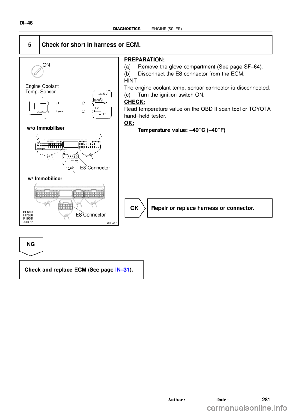
A03011A03412
Engine Coolant
Temp. Sensor
THW
E25 V
E1
ON
E8 Connector w/o Immobiliser
w/ Immobiliser
E8 Connector
DI±46
± DIAGNOSTICSENGINE (5S±FE)
281 Author�: Date�:
5 Check for short in harness or ECM.
PREPARATION:
(a) Remove the glove compartment (See page SF±64).
(b) Disconnect the E8 connector from the ECM.
HINT:
The engine coolant temp. sensor connector is disconnected.
(c) Turn the ignition switch ON.
CHECK:
Read temperature value on the OBD II scan tool or TOYOTA
hand±held tester.
OK:
Temperature value: ±40°C (±40°F)
OK Repair or replace harness or connector.
NG
Check and replace ECM (See page IN±31).
Page 2467 of 4770

DI±47
282 Author�: Date�:
DTC P0116 Engine Coolant Temp. Circuit Range/
Performance Problem
CIRCUIT DESCRIPTION
Refer to DTC P0115 (Engine Coolant Temp. Circuit Malfunc")
± DIAGNOSTICSENGINE (5S±FE)
DI±47
282 Author�: Date�:
DTC P0116 Engine Coolant Temp. Circuit Range/
Performance Problem
CIRCUIT DESCRIPTION
Refer to DTC P0115 (Engine Coolant Temp. Circuit Malfunction) on page DI±41.
DTC No.DTC Detecting ConditionTrouble Area
If THW < ±7°C (19.4°F) or THA < ±7°C (19.4°F) 20 min. or
more after starting engine, engine coolant temp. sensor value
is 30°C (86°F)*1 20°C (48°F)*2 or less
(2 trip detection logic)
If THW ±7°C (19.4°F) and THA � ±7°C (19.4°F) and 10°C
(50°F) at engine start, 5 min. or more after starting engine,
engine coolant temp. sensor value is 30°C (86°F)*1 20°C
(48°F)*2 or less
(2 trip detection logic)
P0116 If THW � 10°C (50°F) and THA � 10°C (50°F) at engine
start, 2 min. or more after starting engine, engine coolant temp.
sensor value is 30°C (86°F)*1 20°C (48°F)*2 or less
(2 trip detection logic)�Engine coolant temp. sensor
�Cooling system
When THW 35°C (95°F) and 60°C (140°F), THA �
±6.7°C (19.9°F) when starting the engine, condition (a) and
(b) continues:
(a) Vehicle speed is changing (Not stable)
(b) Water temperature change is lower than 3°C (37.4°F) from
the water temperature since when sterting the engine
(2 trip detection logic)
*1: Except California Specification vehicles.
*2: Only for California Specification vehicles.
INSPECTION PROCEDURE
HINT:
�If DTCs P0115 (Engine Coolant Temp. Circuit Malfunction) and P0116 (Engine Coolant Temp. Circuit
Range/Performance Problem) are output simultaneously, engine coolant temp. sensor circuit may be
open. Perform troubleshooting of DTC P0115 first.
�Read freeze frame data using TOYOTA hand±held tester or OBD II scan tool. Because freeze frame
records the engine conditions when the malfunction is detected, when troubleshooting it is useful for
determining whether the vehicle was running or stopped, the engine warmed up or not, the air±fuel
ratio lean or rich, etc. at the time of the malfunction.
1 Are there any other codes (besides DTC P0116) being output?
YES Go to relevant DTC chart.
NO
DI00Q±05