Page 4533 of 4770

READINESS MONITOR DRIVE PATTERNS ± EG003-02 RevisedMarch 29, 2002
Page 2 of 23
J1930 TERMJ1930 DEFINITIONTOYOTA/LEXUS DIAGNOSTIC TESTER PARAMETER
IATIntake Air TemperatureIntake Air
ECTEngine Coolant TemperatureCoolant Temp
TOOLS & MATERIALPART NUMBERQUANTITY
Toyota Diagnostic Tester Kit010012711
12 Megabyte Diagnostic Tester Program Card
with version 9.0a Software (or later)01002593-0051
NOTE:
A generic OBDII Scantool can be used in place of the Toyota Diagnostic Tester.
CAUTION:
Strict observance of posted speed limits, traffic laws and road conditions are
required when performing these drive patterns.
NOTE:
�These drive patterns represent the fastest method to satisfy all necessary
conditions which allow the specific Readiness Monitor to complete.
�In the event that the drive pattern must be interrupted (possibly due to traffic
conditions or other factors) the drive pattern can be resumed and, in most cases,
the Readiness Monitor will still set to ªcomplete.º
�To ensure rapid completion of Readiness Monitors, avoid sudden changes in
vehicle load and speed (driving up and down hills and/or sudden acceleration).
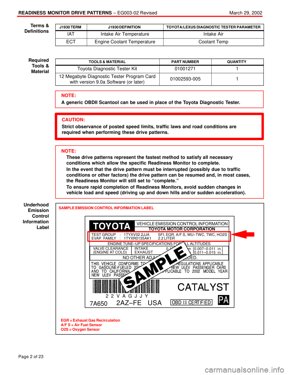
SAMPLE EMISSION CONTROL INFORMATION LABEL
EGR = Exhaust Gas Recirculation
A/F S = Air Fuel Sensor
O2S = Oxygen Sensor
0.19±0.29 mm [0.007±0.011 in.]
0.28±0.38 mm [0.011±0.015 in.]INTAKE
EXHAUSTVALVE CLEARANCE
(ENGINE AT COLD)
NO OTHER ADJUSTMENTS NEEDED.
ENGINE TUNE±UP SPECIFICATIONS FOR ALL ALTITUDES
7A650
2 2 V A G J J Y
2AZ±FE USA
SFI, EGR, A/F S, WU±TWC, TWC, HO2S
2.2 LITER TEST GROUP : 1TYXV02.2JJA
EVAP. FAMILY : 1TYXR0135AK1
TOYOTA MOTOR CORPORATION VEHICLE EMISSION CONTROL INFORMATION
Terms &
Definitions
Required
Tools &
Material
Underhood
Emission
Control
Information
Label
Page 4706 of 4770
TRANSMISSION OIL COOLER INSTALLATION ± TC003±97 October 17, 1997
Procedure1. Parts removal in preparation for cooler
installation:
A. Remove the 9 bolts, 2 screws and
the center engine under cover.
B. Remove the engine coolant
temperature switch connector and
the wire clamp.
C. Remove battery and tray.
D. Disconnect the cooling fan
connector.
E. Disconnect the No.1 engine coolant
temperature switch wire connector.
F. Remove the 2 bolts and then the
cooling fan.
Page 2 of 6
Fig. 2Center Engine Under Cover
Fig. 3ClampSwitch
Fig. 4
Page 4710 of 4770

TRANSMISSION OIL COOLER INSTALLATION ± TC003±97 October 17, 1997
Procedure3. Final Assembly:
(Continued)
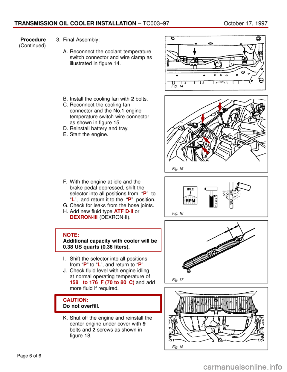
A. Reconnect the coolant temperature
switch connector and wire clamp as
illustrated in figure 14.
B. Install the cooling fan with 2 bolts.
C. Reconnect the cooling fan
connector and the No.1 engine
temperature switch wire connector
as shown in figure 15.
D. Reinstall battery and tray.
E. Start the engine.
F. With the engine at idle and the
brake pedal depressed, shift the
selector into all positions from ªPº to
ªLº, and return it to the ªPº position.
G. Check for leaks from the hose joints.
H. Add new fluid type ATF D´II or
DEXRON´III (DEXRON´II).
NOTE:
Additional capacity with cooler will be
0.38 US quarts (0.36 liters).
I. Shift the selector into all positions
from ªPº to ªLº, and return to ªPº.
J. Check fluid level with engine idling
at normal operating temperature of
158� to 176�F (70 to 80�C) and add
more fluid if required.
CAUTION:
Do not overfill.
K. Shut off the engine and reinstall the
center engine under cover with 9
bolts and 2 screws as shown in
figure 18.
Page 6 of 6
Fig. 15
Fig. 16
Fig. 17
Fig. 18
Page 4719 of 4770

O2S TEST RESULTS (MODE 05) ± SS002-03December 17, 2003
Page 2 of 43
1. Clear any stored Diagnostic Trouble Codes (DTCs) using the Toyota
Diagnostic Tester.
2. Start the engine.
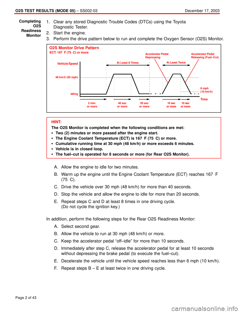
3. Perform the drive pattern below to run and complete the Oxygen Sensor (O2S) Monitor.
O2S Monitor Drive Pattern
ECT: 167�F (75�C) or more
Vehicle Speed
At Least 8 Times
48 km/h (30 mph)
IdlingAt Least Twice Accelerator Pedal
DepressingAccelerator Pedal
Releasing (Fuel±Cut)
6 mph
(10 km/h)
Time2 min.
or more40 sec
or more20 sec
or more10 sec
or more10 sec
or more
HINT:
The O2S Monitor is completed when the following conditions are met:
�Two (2) minutes or more passed after the engine start.
�The Engine Coolant Temperature (ECT) is 167�F (75�C) or more.
�Cumulative running time at 30 mph (48 km/h) or more exceeds 6 minutes.
�Vehicle is in closed loop.
�The fuel±cut is operated for 8 seconds or more (for Rear O2S Monitor).
A. Allow the engine to idle for two minutes.
B. Warm up the engine until the Engine Coolant Temperature (ECT) reaches 167�F
(75�C).
C. Drive the vehicle over 30 mph (48 km/h) for more than 40 seconds.
D. Stop the vehicle and allow the engine to idle for more than 20 seconds.
E. Repeat steps C and D at least 8 times in one driving cycle.
(Do not cycle the ignition key.)
In addition, perform the following steps for the Rear O2S Readiness Monitor:
A. Select second gear.
B. Allow the vehicle to run at 30 mph (48 km/h) or more.
C. Keep the accelerator pedal ªoff±idleº for more than 10 seconds.
D. Immediately after step C, release the accelerator pedal for at least 10 seconds
without depressing the brake pedal (to execute the fuel±cut).
E. Decelerate the vehicle until the vehicle speed reaches less than 6 mph (10 km/h).
F. Repeat steps B ± E at least twice in one driving cycle.
Completing
O2S
Readiness
Monitor