Page 3754 of 4770

MA003±09
MA±4
± MAINTENANCEUNDER HOOD
47 Author�: Date�:
UNDER HOOD
GENERAL MAINTENANCE
1. GENERAL NOTES
�Maintenance items may vary from country to country. Check the owner's manual supplement in which
the maintenance schedule is shown.
�Every service item in the periodic maintenance schedule must be performed.
�Periodic maintenance service must be performed according to whichever interval in the periodic main-
tenance schedule occurs first, the odometer reading (miles) or the time interval (months).
�Maintenance service after the last period should be performed at the same interval as before unless
otherwise noted.
�Failure to do even one item an cause the engine to run poorly and increase exhaust emissions.
2. WINDSHIELD WASHER FLUID
Check that there is sufficient fluid in the tank.
3. ENGINE COOLANT LEVEL
Check that the coolant level is between the ºFULLº and ºLOWº lines on the see±through reservoir.
4. RADIATOR AND HOSES
(a) Check that the front of the radiator is clean and not blocked with leaves, dirt or bugs.
(b) Check the hoses for cracks, kinks, rot or loose connections.
5. BATTERY ELECTROLYTE LEVEL
Check that the electrolyte level of all battery cells is between the upper and lower level lines on the case.
6. BRAKE AND CLUTCH FLUID LEVELS
(a) Check that the brake and clutch fluid levels are near the upper level line on the see±through reservoirs.
(b) Check that the clutch fluid level is with is ± 5 mm (0.20 in.). of the reservoir hem.
7. ENGINE DRIVE BELTS
Check drive belt for fraying, cracks, wear or oiliness.
8. ENGINE OIL LEVEL
Check the level on the dipstick with the engine turned off.
9. POWER STEERING FLUID LEVEL
�Check the level.
�The level should be in the ºHOTº or ºCOLDº range depending on the fluid temperature.
10. AUTOMATIC TRANSMISSION FLUID LEVEL
(a) Park the vehicle on a level surface.
(b) With the engine idling and the parking brake applied, shift the selector into all positions from ºPº to ºLº,
and then shift into ºPº position.
(c) Pull out the dipstick and wipe off the fluid with a clean rag. Re±insert the dipstick and check that the
fluid level is in the HOT range.
(d) Do this check with the fluid at normal driving temperature (70 ± 80°C, 158 ± 176°F).
HINT:
Wait until the engine cools down (approx. 30 min.) before checking the fluid level after extended driving at
high speeds, in hot weather, in heavy traffic or pulling a trailer.
11. EXHAUST SYSTEM
If any change in the sound of the exhaust or smell of the exhaust fumes is noticed, have the cause located
and corrected.
Page 4029 of 4770

USA:
Standard indicat")
SS0B0±05
± SERVICE SPECIFICATIONSBODY ELECTRICAL
SS±67
230 Author�: Date�:
BODY ELECTRICAL
SERVICE DATA
TURN SIGNAL FLASHER
Flashes/ Minute60 ± 120
SPEEDOMETER (ON±VEHICLE)
USA:
Standard indication (mph)Allowable range (mph)
2018 ± 24
4038 ± 44
6056 ± 66
8078 ± 88
10098 ± 110
120118 ± 132
CANADA:
Standard indication (km/h)Allowable range (km/h)
2017 ± 24
4038 ± 46
6057.5 ± 67
8077 ± 88
10096 ± 109
120115 ± 130
140134 ± 151.5
160153 ± 173
TACHOMETER (ON±VEHICLE)/ DC 13.5 V 25 °C at (77 °F)
Standard indicationAllowable range
700630 ± 770
1,000900 ± 1,100
2,0001,850 ± 2,150
3,0002,800 ± 3,200
4,0003,800 ± 4,200
5,0004,800 ± 5,200
6,0005,750 ± 6,250
7,0006,700 ± 7,300
FUEL RECEIVER GAUGE
A ± BApprox. 126.2 W
A ± CApprox. 280.5 W
B ± CApprox. 154.3 W
FUEL SENDER GAUGE
Float position mm (in.)Resistance (W)
F: Approx. ±91.1 (±3.587)Approx. 3.0
1/2: Approx. ±34.2 (±1.346)Approx. 31.7
E: Approx. 30.8 (1.213)Approx. 110.0
ENGINE COOLANT TEMPERATURE RECEIVER GAUGE (Resistance)
A ± BApprox. 175.7 W
A ± CApprox. 54.0 W
Page 4030 of 4770
SS±68
± SERVICE SPECIFICATIONSBODY ELECTRICAL
231 Author�: Date�:
B ± CApprox. 229.7 W
ENGINE COOLANT TEMPERATURE SENDER GAUGE (Resistance)
Temperature °C (°F)Resistance (W)
50 (122.0)274
120 (248.0)26.4
Page 4082 of 4770
SF0E5±03
B06361
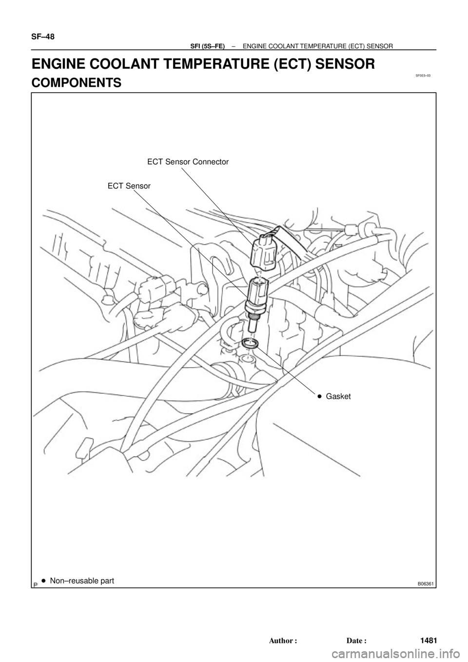
ECT Sensor Connector
ECT Sensor
� Gasket
� Non±reusable part
SF±48
± SFI (5S±FE)ENGINE COOLANT TEMPERATURE (ECT) SENSOR
1481 Author�: Date�:
ENGINE COOLANT TEMPERATURE (ECT) SENSOR
COMPONENTS
Page 4083 of 4770
SF0E6±03
S01196S01699Z17274
Ohmmeter
Resistance kW
Temperature °C (°F) Acceptable 30
20
10
5
3
2
1
0.5
0.3
0.2
0.1
40 ±20 0 20 60 80 100
(212) (176) (140) (104) (68) (32) (±4)
± SFI (5S±FE)ENGINE COOLANT TEMPERATURE (ECT) SENSOR
SF±49
1482 Author�: Date�:
INSPECTION
1. DRAIN ENGINE COOLANT
2. REMOVE ECT SENSOR
3. INSPECT ECT SENSOR
Using an ohmmeter, measure the resistance between the ter-
minals.
Resistance: Refer to the graph
If the resistance is not as specified, replace the ECT sensor.
4. REINSTALL ECT SENSOR
5. REFILL WITH ENGINE COOLANT
Page 4139 of 4770
SF07V±03
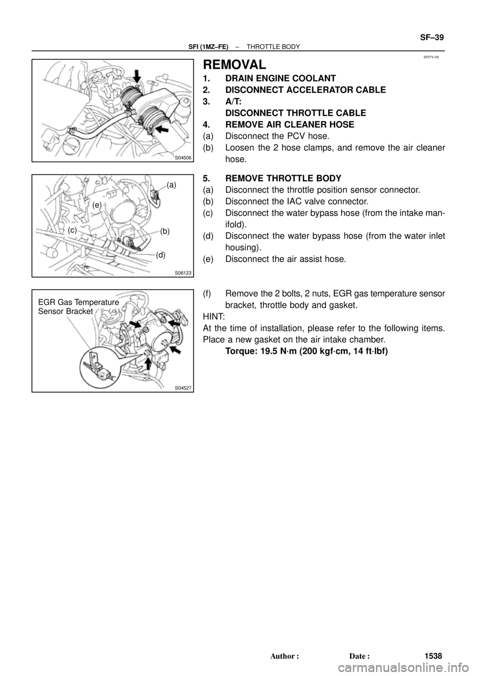
S04506
S06123
(a)
(b)
(d) (e)
(c)
S04527
EGR Gas Temperature
Sensor Bracket
± SFI (1MZ±FE)THROTTLE BODY
SF±39
1538 Author�: Date�:
REMOVAL
1. DRAIN ENGINE COOLANT
2. DISCONNECT ACCELERATOR CABLE
3. A/T:
DISCONNECT THROTTLE CABLE
4. REMOVE AIR CLEANER HOSE
(a) Disconnect the PCV hose.
(b) Loosen the 2 hose clamps, and remove the air cleaner
hose.
5. REMOVE THROTTLE BODY
(a) Disconnect the throttle position sensor connector.
(b) Disconnect the IAC valve connector.
(c) Disconnect the water bypass hose (from the intake man-
ifold).
(d) Disconnect the water bypass hose (from the water inlet
housing).
(e) Disconnect the air assist hose.
(f) Remove the 2 bolts, 2 nuts, EGR gas temperature sensor
bracket, throttle body and gasket.
HINT:
At the time of installation, please refer to the following items.
Place a new gasket on the air intake chamber.
Torque: 19.5 N´m (200 kgf´cm, 14 ft´lbf)
Page 4163 of 4770
SF08I±03
S04759
ECT Switch19 mm
Deep Socket
Wrench
Gasket
S01196S01699Z17274
Ohmmeter
Resistance kW
Temperature °C (°F) Acceptable 30
20
10
5
3
2
1
0.5
0.3
0.2
0.1
40 ±20 0 20 60 80 100
(212) (176) (140) (104) (68) (32) (±4)
± SFI (1MZ±FE)ENGINE COOLANT TEMPERATURE (ECT) SENSOR
SF±63
1562 Author�: Date�:
ENGINE COOLANT
TEMPERATURE (ECT) SENSOR
INSPECTION
1. DRAIN ENGINE COOLANT
2. REMOVE ECT SENSOR
(a) Disconnect the ECT sensor connector.
(b) Using a 19 mm deep socket wrench, remove the ECT
sensor and gasket.
3. INSPECT ECT SENSOR
Using an ohmmeter, measure the resistance between the ter-
minals.
Resistance: Refer to the graph
If the resistance is not as specified, replace the ECT sensor.
4. REINSTALL ECT SENSOR
(a) Install a new gasket to the ECT sensor.
(b) Using a 19 mm deep socket, install the ECT sensor.
Torque: 20 N´m (200 kgf´cm, 14 ft´lbf)
(c) Connect the ECT sensor connector.
5. REFILL WITH ENGINE COOLANT
Page 4166 of 4770

SF08K±03
B06390
VSV Connector for
EVAP
Ground Cable
PCV Hose
Air Intake Chamber
Assembly
ECT Sensor
Connector ECT Sender
Gauge ConnectorEGR Valve Position
Sensor Connector
IAC Valve
Connector
VSV Connector
for EGR
VSV Connector for ACIS
Engine Wire
Engine Coolant
Reservoir HoseAir Assist Hose
Water Bypass Hose No.2 EGR Pipe
Throttle Position
Sensor Connector
No.1 Engine
HangerBrake Booster
Vacuum Hose Air Intake Chamber Stay
Water OutletPS Pressure Tube
�Gasket
19.5 (200, 14)
39 (400, 19)12 (120, 19)
15 (150, 11)
�Gasket
43 (440, 32)
Ground Starp
DLC1
�Gasket
15 (150, 11)
Grand Strap
Connector
�Gasket
39 (400, 29)
V±Bank Cover
Accelerator Cable
Throttle Cable
Air Cleaner
Hose
Purge HoseEGR Gas Temperature
Sensor Connector
Vacuum
HoseWater Bypass Hose
Fuel Inlet Hose
Heater Hose
Intake Manifold Assembly
Injector Connector x 9
Knock Sensor
Connector
Upper Radiator
Hose
Engine
Wire
Band
High±Tension Cord
Set �Gasket
: Specified torque
�Non±reusable partN´m (kgf´cm, ft´lbf)
�Retainer
Knock Sensor
SF±66
± SFI (1MZ±FE)KNOCK SENSOR
1565 Author�: Date�:
KNOCK SENSOR
COMPONENTS

 Acceptable 30
20
10
5
3
2
1
0.5
0.3
0.2
0.1
40 ±20 0 20 60 80 100
(212) (176) (140) (104) (68) (32) (±4)
± SFI (5S±FE)ENGI")
 Acceptable 30
20
10
5
3
2
1
0.5
0.3
0.2
0.1
40 ±20 0 20 60 80 100
(212) (176")