Page 349 of 4770
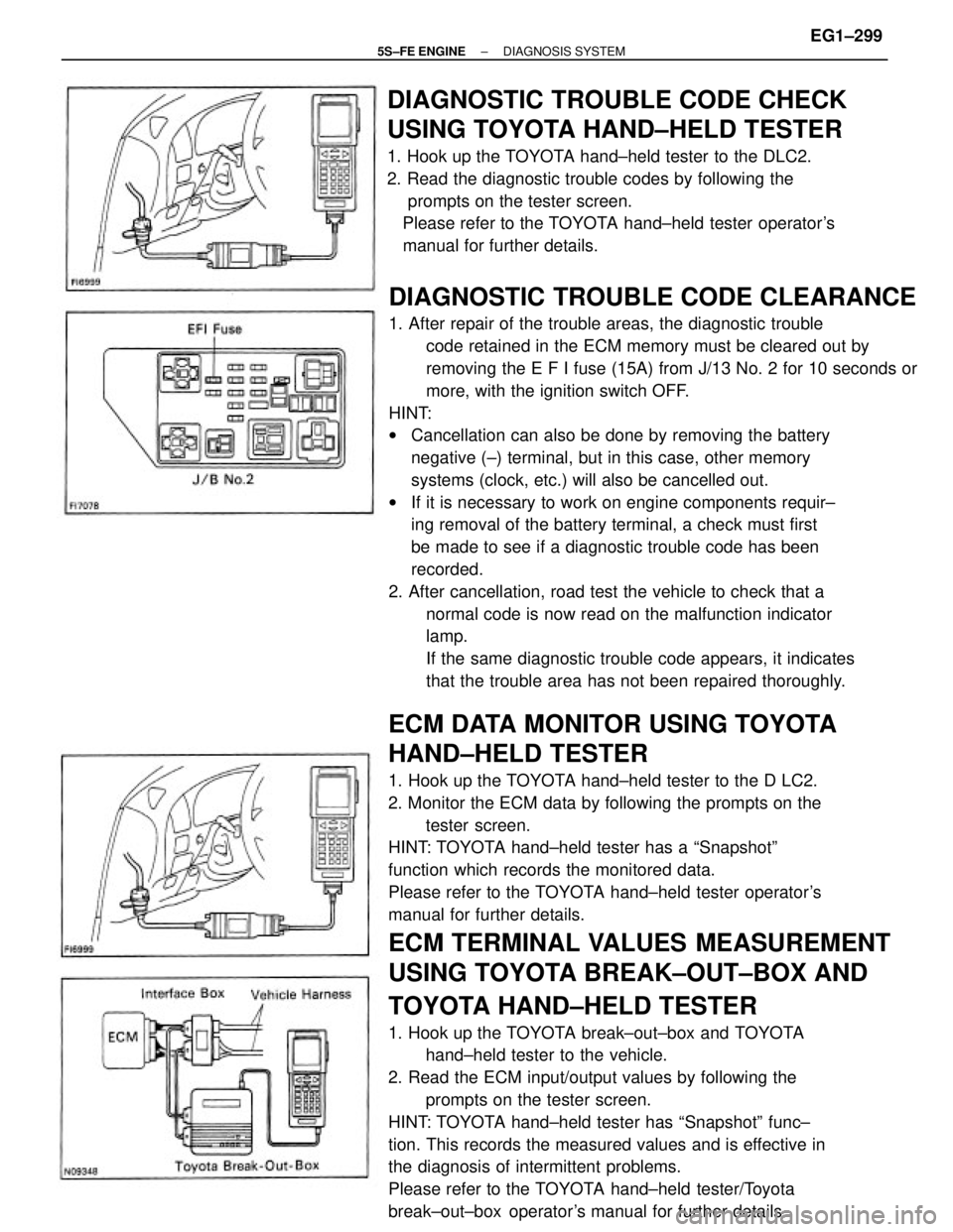
ECM DATA MONITOR USING TOYOTA
HAND±HELD TESTER
1. Hook up the TOYOTA hand±held tester to the D LC2.
2. Monitor the ECM data by following the prompts on the
tester screen.
HINT: TOYOTA hand±held tester has a ªSnapshotº
function which records the monitored data.
Please refer to the TOYOTA hand±held tester operator's
manual for further details.
ECM TERMINAL VALUES MEASUREMENT
USING TOYOTA BREAK±OUT±BOX AND
TOYOTA HAND±HELD TESTER
1. Hook up the TOYOTA break±out±box and TOYOTA
hand±held tester to the vehicle.
2. Read the ECM input/output values by following the
prompts on the tester screen.
HINT: TOYOTA hand±held tester has ªSnapshotº func±
tion. This records the measured values and is effective in
the diagnosis of intermittent problems.
Please refer to the TOYOTA hand±held tester/Toyota
break±out±box operator's manual for further details.
DIAGNOSTIC TROUBLE CODE CLEARANCE
1. After repair of the trouble areas, the diagnostic trouble
code retained in the ECM memory must be cleared out by
removing the E F I fuse (15A) from J/13 No. 2 for 10 seconds or
more, with the ignition switch OFF.
HINT:
wCancellation can also be done by removing the battery
negative (±) terminal, but in this case, other memory
systems (clock, etc.) will also be cancelled out.
wIf it is necessary to work on engine components requir±
ing removal of the battery terminal, a check must first
be made to see if a diagnostic trouble code has been
recorded.
2. After cancellation, road test the vehicle to check that a
normal code is now read on the malfunction indicator
lamp.
If the same diagnostic trouble code appears, it indicates
that the trouble area has not been repaired thoroughly.
DIAGNOSTIC TROUBLE CODE CHECK
USING TOYOTA HAND±HELD TESTER
1. Hook up the TOYOTA hand±held tester to the DLC2.
2. Read the diagnostic trouble codes by following the
prompts on the tester screen.
Please refer to the TOYOTA hand±held tester operator's
manual for further details.
± 5S±FE ENGINEDIAGNOSIS SYSTEMEG1±299
Page 350 of 4770
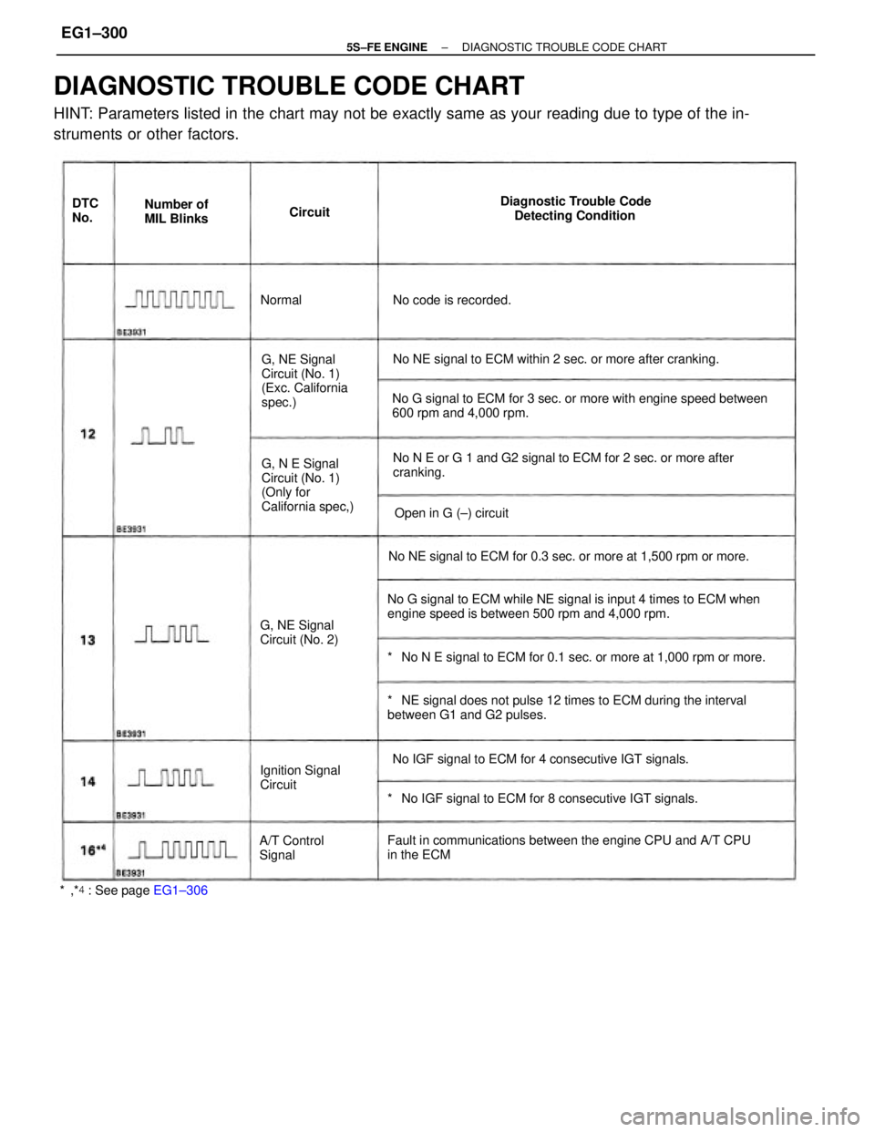
DIAGNOSTIC TROUBLE CODE CHART
HINT: Parameters listed in the chart may not be exactly same as your reading due to type of the in-
struments or other factors.
No G signal to ECM while NE signal is input 4 times to ECM when
engine speed is between 500 rpm and 4,000 rpm.No G signal to ECM for 3 sec. or more with engine speed between
600 rpm and 4,000 rpm.
*� NE signal does not pulse 12 times to ECM during the interval
between G1 and G2 pulses.
Fault in communications between the engine CPU and A/T CPU
in the ECMNo N E or G 1 and G2 signal to ECM for 2 sec. or more after
cranking.
*� No N E signal to ECM for 0.1 sec. or more at 1,000 rpm or more. No NE signal to ECM for 0.3 sec. or more at 1,500 rpm or more.No NE signal to ECM within 2 sec. or more after cranking.
*� No IGF signal to ECM for 8 consecutive IGT signals. No IGF signal to ECM for 4 consecutive IGT signals. G, N E Signal
Circuit (No. 1)
(Only for
California spec,) G, NE Signal
Circuit (No. 1)
(Exc. California
spec.)Diagnostic Trouble Code
Detecting Condition
G, NE Signal
Circuit (No. 2)
Ignition Signal
Circuit
*�,*� : See page EG1±306A/T Control
SignalOpen in G (±) circuit Number of
MIL Blinks
No code is recorded. DTC
No.Circuit
Normal
± 5S±FE ENGINEDIAGNOSTIC TROUBLE CODE CHARTEG1±300
Page 353 of 4770
wOpen or short in injector circuit
wFuel line pressure (injector leak, blockage)
wMechanical system malfunction (skipping teeth of timing
belt)
wIgnition system
w Compression pressure (foreign object caught in valve)
wAir leakage
wECM wOpen or short in main oxygen sensor circuit
wMain oxygen sensor
wignition system
wECM wOpen or short in engine coolant temp. sensor circuit
wEngine coolant temp. sensor
wECM
wOpen or short in intake air temp. sensor circuit
wIntake air temp. sensor
wECM wMain oxygen sensor circuit
w Main oxygen sensorMalfunction
Indicator
Lamp*�
*�,*�: See page EG1±306Normal
Mode Trouble AreaMemory`
Test
ModeSee page
EG1±360
EG1±363EG1±352
EG1±356
± 5S±FE ENGINEDIAGNOSTIC TROUBLE CODE CHARTEG1±303
Page 355 of 4770
wOpen or short in injector circuit
wFuel line pressure (injector leak, blockage)
wMechanical system malfunction (skipping teeth of timing
belt)
wIgnition system
wCompression pressure (foreign object caught in valve)
wAir leakage
w ECM
wOpen or short in No.1 vehicle speed sensor circuit
wNo.1 vehicle speed sensor
wCombination meter
wECM wOpen or short in manifold absolute pressure sensor circuit.
wManifold absolute pressure sensor
wECM
wOpen or short in throttle position sensor circuit
wThrottle position sensor
wECM wOpen or short in sub oxygen sensor circuit
wSub oxygen sensor
wECMMalfunction
Indicator
Lamp*�
*�,*�: See page EG1±306Normal
Mode Trouble Area
Memory*�
Test
ModeSee page
EG1±380EG1±369
EG1±376EG1±372EG1±363
OFF OFF
± 5S±FE ENGINEDIAGNOSTIC TROUBLE CODE CHARTEG1±305
Page 357 of 4770
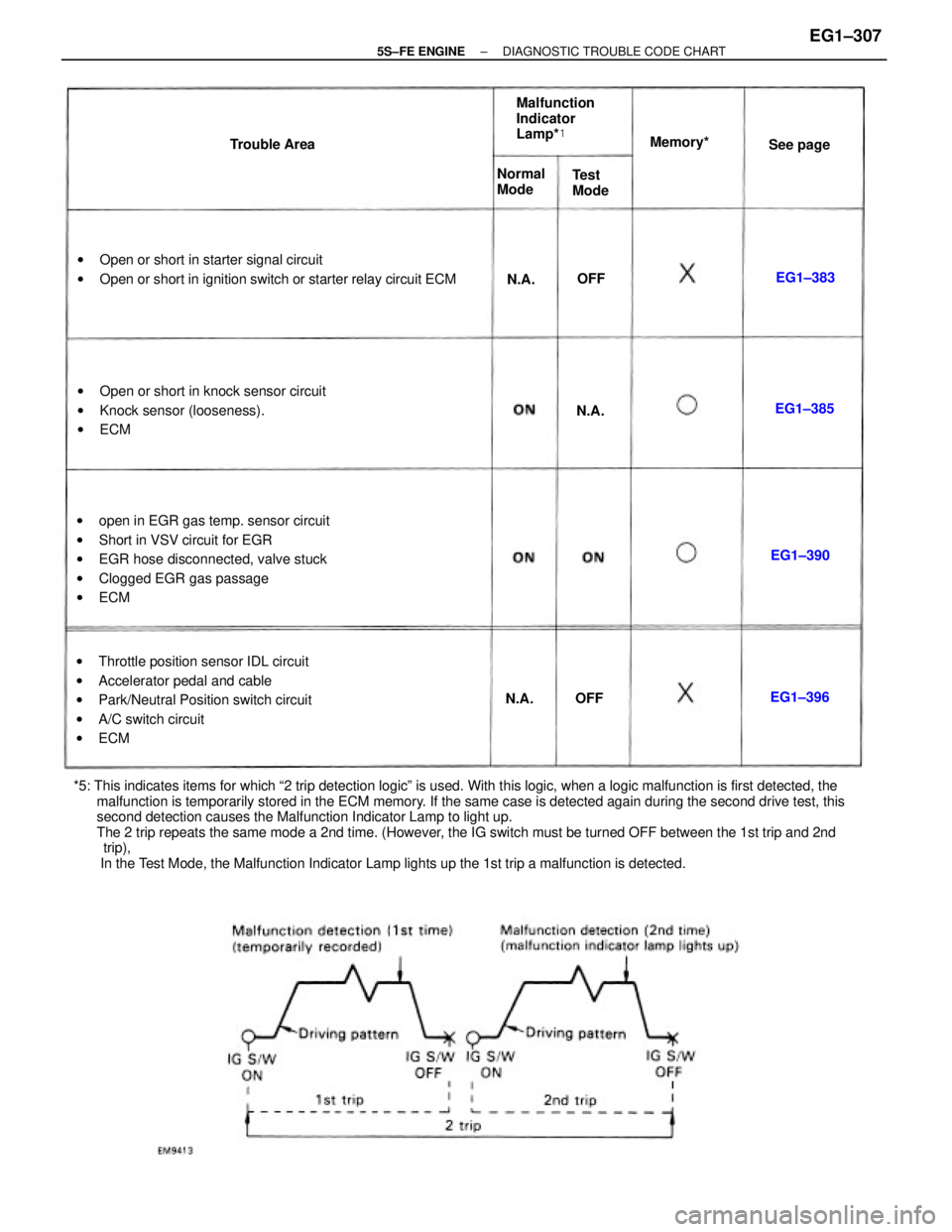
*5: This indicates items for which ª2 trip detection logicº is used. With this logic, when a logic malfunction is first detected, the
malfunction is temporarily stored in the ECM memory. If the same case is detected again during the second drive test, this
second detection causes the Malfunction Indicator Lamp to light up.
The 2 trip repeats the same mode a 2nd time. (However, the IG switch must be turned OFF between the 1st trip and 2nd
trip),
In the Test Mode, the Malfunction Indicator Lamp lights up the 1st trip a malfunction is detected.wopen in EGR gas temp. sensor circuit
wShort in VSV circuit for EGR
wEGR hose disconnected, valve stuck
wClogged EGR gas passage
wECM
wThrottle position sensor IDL circuit
wAccelerator pedal and cable
wPark/Neutral Position switch circuit
wA/C switch circuit
wECM wOpen or short in starter signal circuit
wOpen or short in ignition switch or starter relay circuit ECM
wOpen or short in knock sensor circuit
wKnock sensor (looseness).
wECMMalfunction
Indicator
Lamp*�
Normal
Mode Trouble AreaMemory*�
Test
ModeSee page
EG1±390EG1±385
EG1±396EG1±383
N.A.N.A.
N.A.
OFFOFF
± 5S±FE ENGINEDIAGNOSTIC TROUBLE CODE CHARTEG1±307
Page 358 of 4770
*: Only for California specification vehicles.
Back±Up Function
If there is trouble with the program in the ECM and the ignition signals (IGT) are not output from
microcomputer the ECM controls fuel injection and ignition timing at predetermined levels as a back±up
function to make it possible to continue to operate the vehicle.
Furthermore, the injection duration is calculated from the starting signal (STA) and the throttle position
signal (IDL). Also, the ignition timing is fixed at the initial ignition timing, 5� BTDC, without relation to
the engine speed.
HINT: If the engine is controlled by the back±up function, the malfunction indicator lamp lights up to
warn the driver of the malfunction but the diagnostic trouble code is not output.
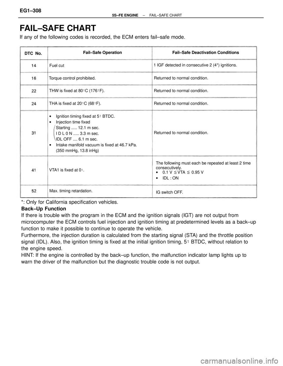
FAIL±SAFE CHART
If any of the following codes is recorded, the ECM enters fail±safe mode.
wIgnition timing fixed at 5� BTDC.
wInjection time fixed
Starting ..... 12.1 m sec.
I D L 0 N ..... 3.3 m sec.
IDL OFF .... 6.1 m sec.
wIntake manifold vacuum is fixed at 46.7 kPa.
(350 mmHg, 13.8 inHg)
The following must each be repeated at least 2 time
consecutively.
w0.1 V �VTA � 0.95 V
wIDL : ON 1 IGF detected in consecutive 2 (4*) ignitions.Fail±Safe Deactivation Conditions
THW is fixed at 80�C (176�F).
THA is fixed at 20�C (68�F). Returned to normal condition.Returned to normal condition.
Returned to normal condition. Returned to normal condition. Torque control prohibited.
Max. timing retardation.Fail±Safe Operation
VTA1 is fixed at 0
�.
IG switch OFF. DTC No.
Fuel cut
± 5S±FE ENGINEFAIL±SAFE CHARTEG1±308
Page 359 of 4770
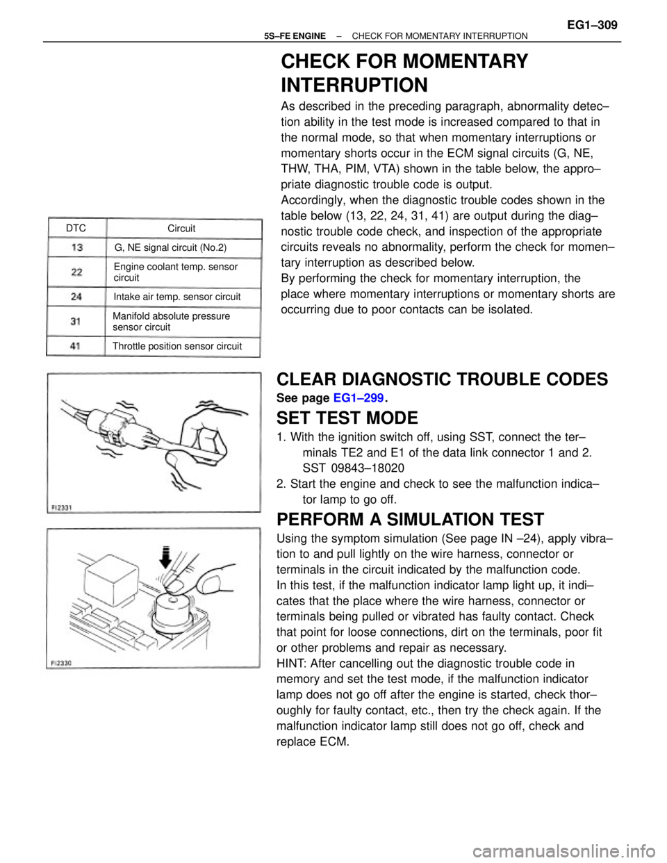
CLEAR DIAGNOSTIC TROUBLE CODES
See page EG1±299.
SET TEST MODE
1. With the ignition switch off, using SST, connect the ter±
minals TE2 and E1 of the data link connector 1 and 2.
SST 09843±18020
2. Start the engine and check to see the malfunction indica±
tor lamp to go off.
PERFORM A SIMULATION TEST
Using the symptom simulation (See page IN ±24), apply vibra±
tion to and pull lightly on the wire harness, connector or
terminals in the circuit indicated by the malfunction code.
In this test, if the malfunction indicator lamp light up, it indi±
cates that the place where the wire harness, connector or
terminals being pulled or vibrated has faulty contact. Check
that point for loose connections, dirt on the terminals, poor fit
or other problems and repair as necessary.
HINT: After cancelling out the diagnostic trouble code in
memory and set the test mode, if the malfunction indicator
lamp does not go off after the engine is started, check thor±
oughly for faulty contact, etc., then try the check again. If the
malfunction indicator lamp still does not go off, check and
replace ECM.
CHECK FOR MOMENTARY
INTERRUPTION
As described in the preceding paragraph, abnormality detec±
tion ability in the test mode is increased compared to that in
the normal mode, so that when momentary interruptions or
momentary shorts occur in the ECM signal circuits (G, NE,
THW, THA, PIM, VTA) shown in the table below, the appro±
priate diagnostic trouble code is output.
Accordingly, when the diagnostic trouble codes shown in the
table below (13, 22, 24, 31, 41) are output during the diag±
nostic trouble code check, and inspection of the appropriate
circuits reveals no abnormality, perform the check for momen±
tary interruption as described below.
By performing the check for momentary interruption, the
place where momentary interruptions or momentary shorts are
occurring due to poor contacts can be isolated.
Engine coolant temp. sensor
circuit
Manifold absolute pressure
sensor circuit
Throttle position sensor circuitIntake air temp. sensor circuitG, NE signal circuit (No.2)Circuit DTC
± 5S±FE ENGINECHECK FOR MOMENTARY INTERRUPTIONEG1±309
Page 361 of 4770
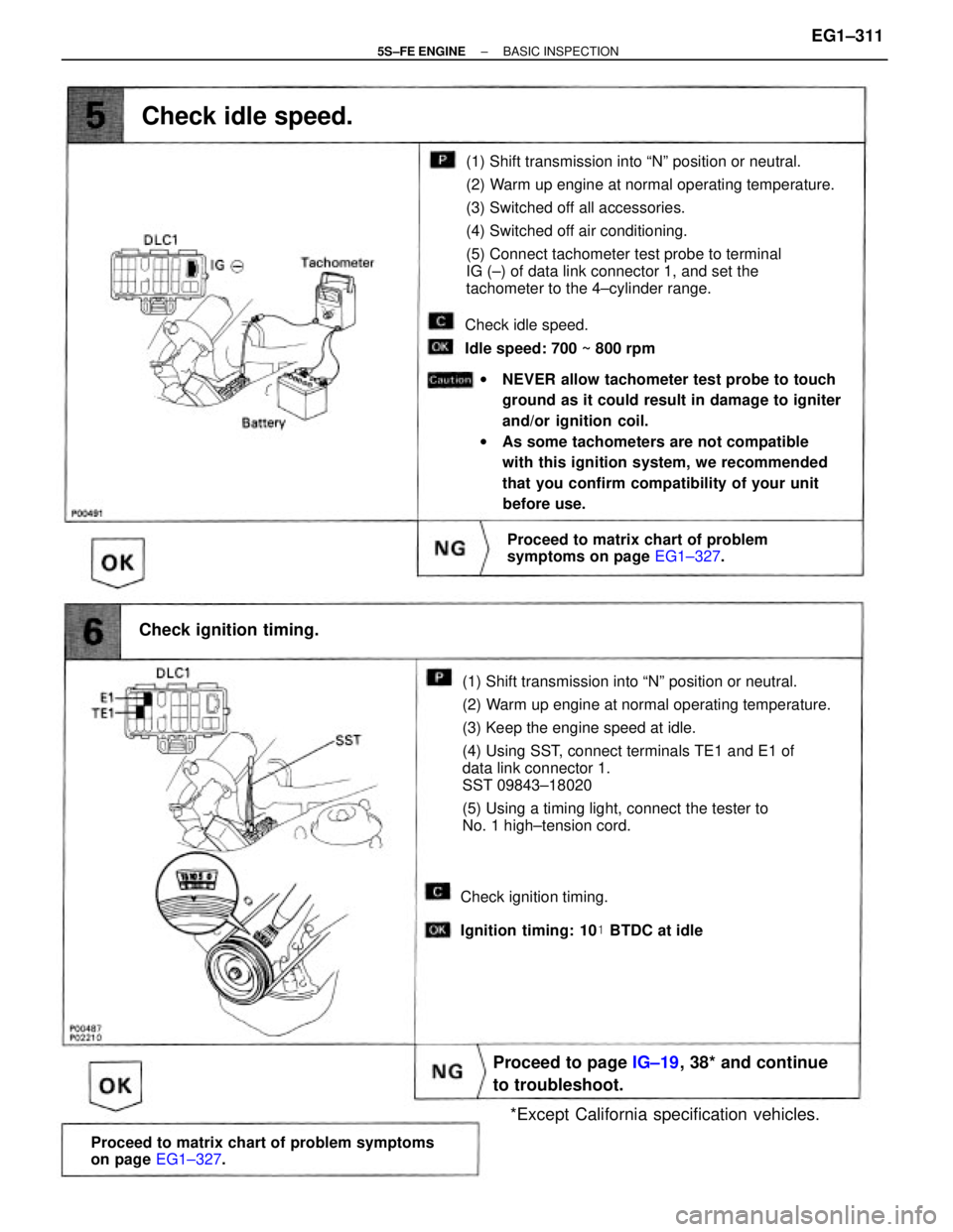
(1) Shift transmission into ªNº position or neutral.
(2) Warm up engine at normal operating temperature.
(3) Keep the engine speed at idle.
(4) Using SST, connect terminals TE1 and E1 of
data link connector 1.
SST 09843±18020
(5) Using a timing light, connect the tester to
No. 1 high±tension cord.(1) Shift transmission into ªNº position or neutral.
(2) Warm up engine at normal operating temperature.
(3) Switched off all accessories.
(4) Switched off air conditioning.
(5) Connect tachometer test probe to terminal
IG (±) of data link connector 1, and set the
tachometer to the 4±cylinder range.
wNEVER allow tachometer test probe to touch
ground as it could result in damage to igniter
and/or ignition coil.
wAs some tachometers are not compatible
with this ignition system, we recommended
that you confirm compatibility of your unit
before use.
Proceed to matrix chart of problem symptoms
on page EG1±327.
Proceed to page IG±19, 38* and continue
to troubleshoot.
Proceed to matrix chart of problem
symptoms on page EG1±327.
*Except California specification vehicles. Check ignition timing.
Check idle speed.
Check idle speed.
Idle speed: 700 ~ 800 rpm
Check ignition timing.
Ignition timing: 10� BTDC at idle
± 5S±FE ENGINEBASIC INSPECTIONEG1±311