Page 432 of 4770
(1) Remove glove compartment.
(See page EG1±234).
(2) Disconnect cruise control ECU connector.
(3) Shift the shift lever to N position or neutral.
(4) Jack up a front wheel on one side.
(5) Turn ignition switch on. Drive the vehicle and check if the operation of the speedometer in the combination meter is
normal.
The No. 1 vehicle speed sensor is operating normally if the speedometer display is normal.
Check voltage between terminal SPD of engine control module
connector and body ground.
Check speedometer circuit. See combination
meter troubleshooting on page BE±66.
Check speedometer circuit. See combination
meter troubleshooting on page BE±66.
Check operation of speedometer.
Check and replace engine control module.
INSPECTION PROCEDURE
Measure voltage between terminal SPD of
engine control module connector and body
ground when the wheel is turned slowly.
Voltage is generated intermittently.
± 5S±FE ENGINECIRCUIT INSPECTIONEG1±382
Page 433 of 4770

CIRCUIT DESCRIPTION
When the engine is cranked, the intake air flow is slow, so fuel vaporization is poor. A rich mixture
is therefore necessary in order to achieve good startability. While the engine is being cranked, the
battery positive voltage is applied to terminal STA of the ECM. The starter signal is mainly used to
increase the fuel injection volume for the starting injection control and after±start injection control.
DIAGNOSTIC CHART
HINT: This diagnostic chart is based on the premise that the engine is cranked normally. If the
engine is not cranked, proceed to the matrix chart of problem symptoms on page EG1±327, w
Open or short in starter signal circuit.
wOpen or short in ignition switch or starter
relay circuit.
wECM
Check for open in harness and connector
between ECM and relay.Proceed to next circuit inspection
shown on matrix chart (See page
E±G±327). Diagnostic Trouble Code Detecting Condition
Repair or replace harness or
connector.
WIRING DIAGRAM
No starter signal to ECM.
Check and replace ECM.Check for the test mode.Trouble Area
DTC 43 Starter Signal Circuit
DTC No.
± 5S±FE ENGINECIRCUIT INSPECTIONEG1±383
Page 434 of 4770
Setting the test mode.
(1) Turn ignition switch OFF.
(2) Connect terminals TE2 and E1 of DLC2.
(3) Turn ignition switch ON.
(Don't start the engine)
(4) Connect terminals TE1 and E1 of DLC2.
Check for open in harness and connector between engine control
module and starter relay (See page IN±31). Check output condition of diagnostic trouble code 43.
Proceed to next circuit inspection shown on
matrix chart (See page EG1±327).
Check and replace engine control module.Repair or replace harness or connector.
INSPECTION PROCEDURE
Check if code ª43º is output by the malfunc-
tion indicator lamp.
Code ª43º is output.
Start the engine.
Check if the code ª43º disappear.
Code ª43º is not output.
± 5S±FE ENGINECIRCUIT INSPECTIONEG1±384
Page 435 of 4770

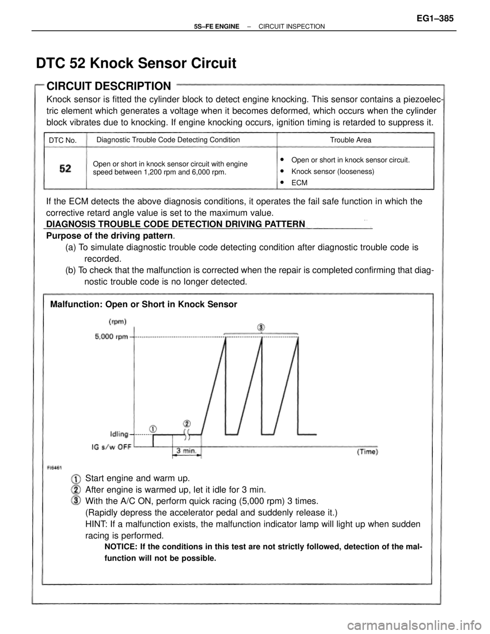
If the ECM detects the above diagnosis conditions, it operates the fail safe function in which the
corrective retard angle value is set to the maximum value.
DIAGNOSIS TROUBLE CODE DETECTION DRIVING PATTERN
Purpose of the driving pattern.
(a) To simulate diagnostic trouble code detecting condition after diagnostic trouble code is
recorded.
(b) To check that the malfunction is corrected when the repair is completed confirming that diag-
nostic trouble code is no longer detected.
Start engine and warm up.
After engine is warmed up, let it idle for 3 min.
With the A/C ON, perform quick racing (5,000 rpm) 3 times.
(Rapidly depress the accelerator pedal and suddenly release it.)
HINT: If a malfunction exists, the malfunction indicator lamp will light up when sudden
racing is performed.
NOTICE: If the conditions in this test are not strictly followed, detection of the mal-
function will not be possible.
CIRCUIT DESCRIPTION
Knock sensor is fitted the cylinder block to detect engine knocking. This sensor contains a piezoelec-
tric element which generates a voltage when it becomes deformed, which occurs when the cylinder
block vibrates due to knocking. If engine knocking occurs, ignition timing is retarded to suppress it.
w
Open or short in knock sensor circuit.
wKnock sensor (looseness)
wECM Open or short in knock sensor circuit with engine
speed between 1,200 rpm and 6,000 rpm.
Malfunction: Open or Short in Knock Sensor
Diagnostic Trouble Code Detecting Condition
Trouble Area
DTC 52 Knock Sensor Circuit
DTC No.
± 5S±FE ENGINECIRCUIT INSPECTIONEG1±385
Page 448 of 4770

Setting the test mode.
(1) Turn ignition switch OFF.
(2) Connect terminals TE2 and E1 of DLC2.
(3) Turn ignition switch ON.
(For checking terminal IDL, disconnect the
vacuum hose from the throttle body, then
apply vacuum to the throttle opener (See page
EG1±204).)
(For checking terminal A/C, start the engine.)
(4) Connect terminals TE1 and E1 of DLC2.
*: Before the STA signal is input (ST is not ON),
diagnostic trouble code 43 is also output. Check output condition of diagnostic trouble code 51.
Proceed to next circuit inspection shown on
matrix chart (See page EG1±327).IDL .... Go to step
A/C ... Go to step
INSPECTION PROCEDURE
PN P ... Go to page
EG1±400. Park/Neutral Position
Switch (PNP)
Accelerator pedal
depressed Accelerator pedal
released
Throttle Position
Sensor ( IDL)R, D, 2 or L position
A/C Switch (A/C)P or N position
A/C SW OFFA/C SW ONCondition
Normal*
Normal*
NormalCode
51*
51*
Check if code ª51º is output by the malfunc-
tion indicator lamp.
Diagnostic trouble code 42 is output with vehicle
speed 3 mph (5 km/h) or below.
± 5S±FE ENGINECIRCUIT INSPECTIONEG1±398
Page 449 of 4770

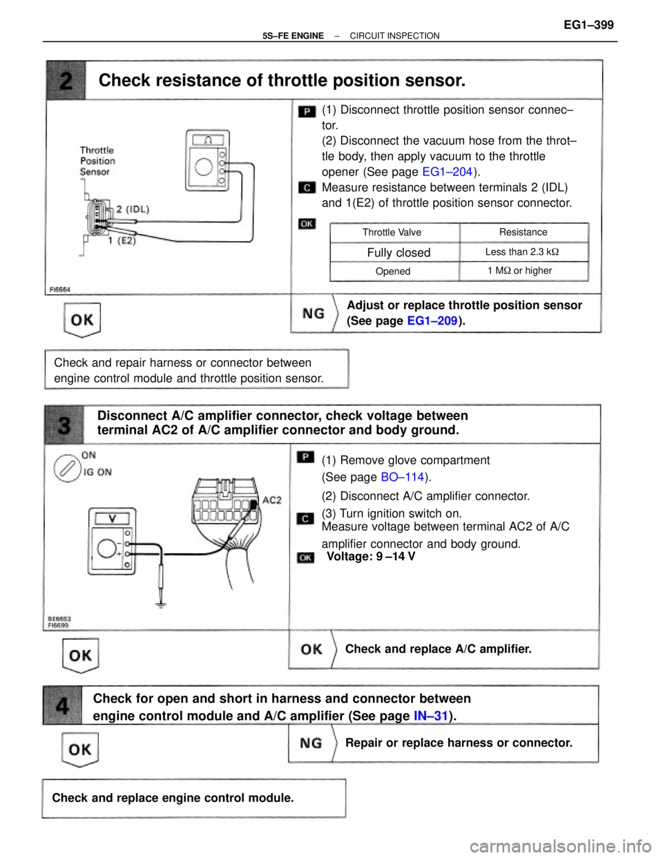
(1) Remove glove compartment
(See page BO±114).
(2) Disconnect A/C amplifier connector.
(3) Turn ignition switch on.
Measure voltage between terminal AC2 of A/C
amplifier connector and body ground.(1) Disconnect throttle position sensor connec±
tor.
(2) Disconnect the vacuum hose from the throt±
tle body, then apply vacuum to the throttle
opener (See page EG1±204).
Measure resistance between terminals 2 (IDL)
and 1(E2) of throttle position sensor connector.
Check for open and short in harness and connector between
engine control module and A/C amplifier (See page IN±31). Disconnect A/C amplifier connector, check voltage between
terminal AC2 of A/C amplifier connector and body ground.
Check and repair harness or connector between
engine control module and throttle position sensor.Adjust or replace throttle position sensor
(See page EG1±209).
Check resistance of throttle position sensor.
Check and replace engine control module.Repair or replace harness or connector. Check and replace A/C amplifier.
1 M� or higher Less than 2.3 k� Throttle Valve
Fully closed
Resistance
Opened
Voltage: 9 ±14 V
± 5S±FE ENGINECIRCUIT INSPECTIONEG1±399
Page 452 of 4770
(1) Connect terminals TE2 and E1 of DLC2.
(2) Turn ignition switch on.
(3) Crank the engine.
(4) Connect terminals TE1 and E1 of DLC2.
Check if diagnostic trouble code ª51º is output
when the shift lever is in the P and D shift positions.
Check for open in harness and connector between engine control
module and park/neutral position switch (See page
IN±31).
Check park/neutral position switch (See page
AX1±92). Check output condition of diagnostic trouble code 51.
Proceed to next circuit inspection shown on
matrix chart (See age EG1±327).
Replace park/neutral position switch.Check and replace engine control module.
Check and replace engine control module.Repair or replace harness or connector.
INSPECTION PROCEDURE
NG
Type II NG
Type I
Shift
Position
Go to stepGo to step
Normal Code
Normal Code Normal CodeNG Type
IIN G Type I
Code 51Code 51
Code 51Result
ºDºªPº
± 5S±FE ENGINECIRCUIT INSPECTIONEG1±402
Page 453 of 4770

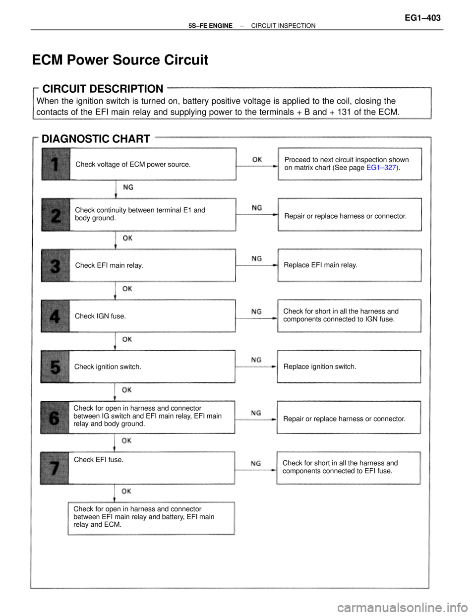
CIRCUIT DESCRIPTION
When the ignition switch is turned on, battery positive voltage is applied to the coil, closing the
contacts of the EFI main relay and supplying power to the terminals + B and + 131 of the ECM.
Check for open in harness and connector
between IG switch and EFI main relay, EFI main
relay and body ground.
Check for open in harness and connector
between EFI main relay and battery, EFI main
relay and ECM.Check continuity between terminal E1 and
body ground.Proceed to next circuit inspection shown
on matrix chart (See page EG1±327).
Check for short in all the harness and
components connected to IGN fuse.
Check for short in all the harness and
components connected to EFI fuse.
ECM Power Source Circuit
Repair or replace harness or connector.
Repair or replace harness or connector. Check voltage of ECM power source.
DIAGNOSTIC CHART
Replace ignition switch.
Check EFI fuse.Replace EFI main relay.
Check ignition switch.Check EFI main relay.
Check IGN fuse.
± 5S±FE ENGINECIRCUIT INSPECTIONEG1±403