Page 589 of 4770
114BODY ELECTRICALÐACCESSORIES
�Operation�
3) Inflator of Morton Made
The inflator of Morton made is comprised of a squib, projectile, orifice disk, propellant grain, hight pressure argon
gas and etc.
If the airbag sensor is turned on by deceleration due to frntal collision, electric current then ignites the squib located
in the inflator. The projectile which fired by the ignition of the squib pierces through the orifice disk and collides with
the action piston, which causes the primer to ignite. The flame wo the primer spreads instantaneously to the ignition
booser and to the propellant grain. The gas which expanded by the heat of the ignition of the propellant grain flows
into the airbag via the gas release hole, thus inflating the airbag.
Page 592 of 4770

117 BODY ELECTRICALÐACCESSORIES
2) Auto Cancel Function
When the vehicle is being driven under cruise control, if any of th econditions listed below is present, the vehicle speed
stored in membor is deleted, the control is lifetd, the current to the actuator is disrupted, and th power indicator ligh
is made to flash. The methods to reactivate the cruise control at that time, in accordance with that particular condition
(malfunction category A or B), are classified in the chart below.
Other auto cancel functions are basically the same as those of the previous model.
Condition
Malfunction CategoryHow to reactivate
�Continuous current applied to the motor's accel-
eration output.
�The motor did not move.
A
Turn off the ignition switch, and
turn it back on. Then turn on the
main switch.
�Excessive current flowed to the motor or
magnetic clutch drive transistor.
�Open circuit in magnetic clutch.
�The vehicle speed signal is not sent for a
predetermined period of time (approx. 140 msec.)
�The vehicle speed is equal to the set speed minus
approximately 16 km/h (10 mph) or below.
�Short circuit in the control switch.
�An open circuit malfunction of the ªdecreaseº
side of the motor (including open circuit in the
motor).
�Abnormal vehicle speed signal.
BTurn the main switch back on.
3) Diagnosis Function
a. Wawrning Indication
The cruise control ECU immediately blinks the power indicator light in the combination meter on and off repeatedly
to alert the driver of a system malfunction.
When the power indicator light is flashing, and the cruise control is released by pressing on the main switch, the power
indicator light will be turned off. When the main switch is turned back on, the power indicator light blinking pattern
as shown on the next page outputs according to the malfunction categories A or B. When a category A malfunction
is occuring, the power indicator ligh will flash again. This indicates that the system cannot operate. But if it is a
category B malfunction, the indicator light will remain on indicating that the system is operating.
Page 603 of 4770

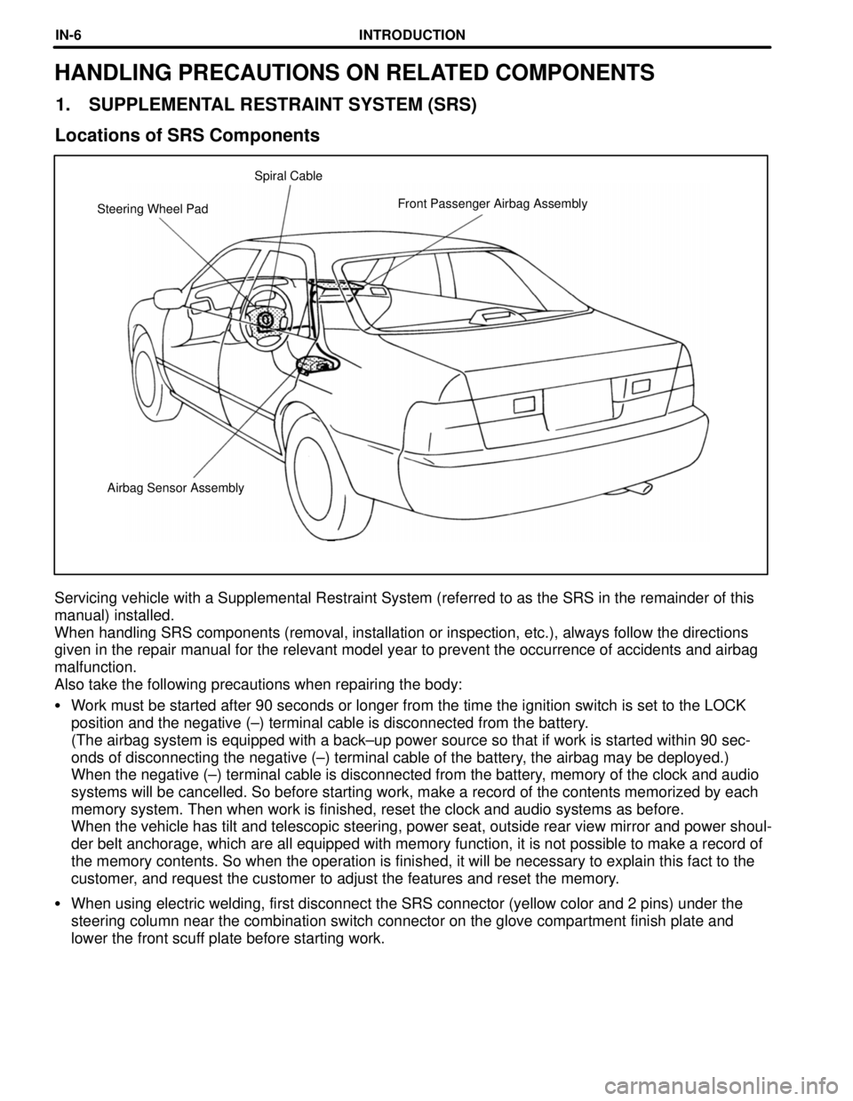
Airbag Sensor Assembly Steering Wheel PadFront Passenger Airbag Assembly Spiral Cable
HANDLING PRECAUTIONS ON RELATED COMPONENTS
1. SUPPLEMENTAL RESTRAINT SYSTEM (SRS)
Locations of SRS Components
Servicing vehicle with a Supplemental Restraint System (referred to as the SRS in the remainder of this
manual) installed.
When handling SRS components (removal, installation or inspection, etc.), always follow the directions
given in the repair manual for the relevant model year to prevent the occurrence of accidents and airbag
malfunction.
Also take the following precautions when repairing the body:
�Work must be started after 90 seconds or longer from the time the ignition switch is set to the LOCK
position and the negative (±) terminal cable is disconnected from the battery.
(The airbag system is equipped with a back±up power source so that if work is started within 90 sec-
onds of disconnecting the negative (±) terminal cable of the battery, the airbag may be deployed.)
When the negative (±) terminal cable is disconnected from the battery, memory of the clock and audio
systems will be cancelled. So before starting work, make a record of the contents memorized by each
memory system. Then when work is finished, reset the clock and audio systems as before.
When the vehicle has tilt and telescopic steering, power seat, outside rear view mirror and power shoul-
der belt anchorage, which are all equipped with memory function, it is not possible to make a record of
the memory contents. So when the operation is finished, it will be necessary to explain this fact to the
customer, and request the customer to adjust the features and reset the memory.
�When using electric welding, first disconnect the SRS connector (yellow color and 2 pins) under the
steering column near the combination switch connector on the glove compartment finish plate and
lower the front scuff plate before starting work.
INTRODUCTIONIN-6
Page 719 of 4770

CAMRY ± NEW FEATURES
149EG07
Clamp
Fuel Hose
Fuel Filter 10
Fuel Filter
A quick connector is used to connect the fuel fil-
ter and the fuel hose together to improve seri-
viceability.
6. Engine Control System
General
The California specification automatic transaxle model has adopted an air-fuel sensor. All models are avail-
able with the Engine Immobiliser System as an optional equipment. The models other than the California
specification automatic transaxle model are basically the same as the '97 models except for the adoption
of the Engine Immobiliser System.
SFI (Sequential Multiport Fuel Injection)
The precision of the air-fuel ratio feedback control has been improved through the adoption of the air-fuel
ratio sensor. The operation of the air-fuel ratio sensor and the ECM are the same as those of the California
specification model with the 5S-FE engine and automatic transaxle. For details, see the '97 Camry New Car
Features (Pub. No. NCF134U).
Engine Immobiliser System
The engine immobiliser system has been designed to prevent the vehicle from being stolen. This system
uses an ECM that stores the ID code of the authorized ignition key. If an attempt is made to start the engine
using an unauthorized key, the ECM prohibits fuel delivery and ignition effectively disabling the engine.
For details, see page 23 in the Engine Immobiliser system section.
Page 720 of 4770

CAMRY ± NEW FEATURES
No.2 INJECTOR
SENSORS ACTUATORS
VG
RSO IGF NE
ECM
IGTI�
IGT3
#10
G22
THW
THA
VTA1
STA
SPD
AFR
AFL
OXS
EGLS
THG
KNKR
CF
NSW
A/C
ACIS
FC
ACT
MAFR
HAFL
HREL
#20
#30
#40
#50
#60
MASS AIR FLOW METER
R, 2, L KNKLIGSW
RSC
CRANKSHAFT POSITION SENSOR
�Engine Speed Signal
�Crankshaft Angle Signal
CAMSHAFT POSITION SENSOR
�Crankshaft Angle Signal
ENGINE COOLANT TEMP.
SENSOR
INTAKE AIR TEMP. SENSOR
THROTTLE POSITION SENSOR
�Throttle Position Signal
IGNITION SWITCH
�Starting Signal
�Ignition Signal
VEHICLE SPEED SENSOR
COMBINATION METER
AIR-FUEL RATIO SENSOR
(Bank 1, Sensor 1)
AIR-FUEL RATIO SENSOR
(Bank 2, Sensor 1)
HEATED OXYGEN SENSOR
(Bank 1, Sensor 2)
EGR VALVE POSITION SENSOR
EGR GAS TEMP. SENSOR
KNOCK SENSORS
PARK / NEUTRAL POSITION
SWITCH
�Neutral Start Signal
AIR CONDITIONING AMPLIFIER
�A / C Switch Signal
COOLING FAN RELAYNo.1 INJECTOR
No.3 INJECTOR
No.4 INJECTOR
No.5 INJECTOR
No.6 INJECTOR
ESA
IGNITER
IGNITION COILS
SPARK PLUGS
IAC
CONTROL VALVE
ACIS
VSV
FUEL PUMP CONTROL
CIRCUIT OPENING RELAY
AIR CONDITIONING CONTROL
AIR CONDITIONING
AMPLIFIER
AIR FUEL RATIO SENSOR
HEATER CONTROL
AIR FUEL RATIO SENSOR
HEATER RELAY
AIR FUEL RATIO SENSOR
HEATER (Bank 1, Sensor 1)
AIR FUEL RATIO SENSOR
HEATER (Bank 1, Sensor 2)SFI
(Continued)
KNOCK SENSORS
11
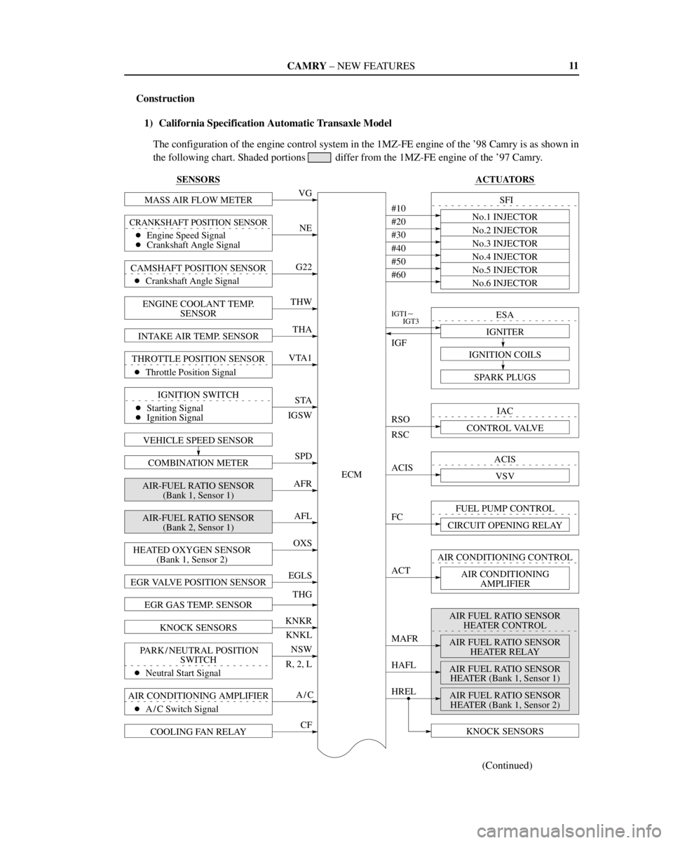
Construction
1) California Specification Automatic Transaxle Model
The configuration of the engine control system in the 1MZ-FE engine of the '98 Camry is as shown in
the following chart. Shaded portions
differ from the 1MZ-FE engine of the '97 Camry.
Page 722 of 4770
CAMRY ± NEW FEATURES
150EG01
Circuit Opening RelayIgnition
SwitchEFI
Main
Relay
DLC1 Pressure
RegulatorVehicle Speed
SensorPark / Neutral Position Switch*
Fuel Pump
BatteryMIL
Air
Conditioning
Amplifier
DLC3
Stop Light Switch
Electrical Load Switch
Air-Fuel Ratio Sensor Heater Relay
ECM Fuel
Filter
Pulsation
DamperVSV
(for EVAP)Vapor
Pressure
Sensor
VSV
for Vapor
Pressure
Sensor
Charcoal CanisterVCV
Intake Air Temp.
SensorIAC Valve
VSV (for EGR)
Mass Air Flow
Meter
Air-Fuel Ratio Sensor
(Bank 1, Sensor 1)Throttle
Position
Sensor
Actuator
DIS
Injector
VSV (for ACIS)
EGR
Valve
Position
Sensor
EGR
Valve EGR Gas
Temp. Sensor Camshaft
Position
Sensor
Engine Coolant
Temp. SensorWU-TWC
WU-TWC
Crankshaft
Position SensorKnock Sensors
Air-Fuel Ratio Sensor
(Bank 2, Sensor 1)Heated Oxygen Sensor
(Bank 1, Sensor 2)
13
Engine Control System Diagram
1) California Specification Automatic Transaxle Model
*: Only for the Automatic Transaxle Models
Page 724 of 4770

CAMRY ± NEW FEATURES
150NF105 150NF104Inactive Activated Wire
PulleyDrum
Piston
Cylinder
15
�SEAT BELT
1. General
�The front seats are provided with an electrical sensing type seat belt pretensioner and a seat belt force limiter.
In the beginning of a collision, the seat belt pretensioner instantly pulls up the seat belt thus providing the
excellent belt's effectiveness in restraining the occupant.
When the impact of a collision causes the tension of the seat belt applied to the occupant to reach a predeter-
mined level, the force limiter restrains the tension, thus controlling the force applied to the occupant's chest
area.
�In accordance with the ignition signal from the airbag sensor assembly, the seat belt pretensioner activates
simultaneously with the deployment of the
SRS airbags for the driver and front passenger.
2. Seat Belt Pretensioner
Construction and Operation
The seat belt pretensioner consists of the pretensioner mechanism and retracting mechanism.
The pretensioner mechanism consists of a gas generator, piston, wire, drum and etc.
If the airbag sensor is turned on by deceleration due to frontal collision, electric current then ignites the gas
generator located in the pretensioner. As a result, the gas generator emits gas in an extremely short time and
pushes the piston. Since the cable is attached to the piston, the piston will pull on the cable causing the drum
to grab onto the shaft. The shaft will then move in the retracting direction pulling up the belt for a predeter-
mined length.
Page 726 of 4770

CAMRY ± NEW FEATURES
150NF109
150NF110
Side Collision ImpactLeft Side Airbag
Sensor Assembly
Power
Source
Safing
Sensor
Side Airbag
SensorInitiator
Bag
(For Driver) Gas
Inflator
Airbag Sensor
AssemblyCPU
Drive
Circuit
17
�SRS SIDE AIRBAG
1. General
�In conjunction with the energy absorbing doors, the SRS side airbags have been designed to help reducing
the impact energy that is transmitted to the driver and front passenger in the event of a side collision. In
a side collision, the side airbag sensor detects the shock and if the side-to-side shock is greater that a speci-
fied value, the airbags stored in the seat back for the driver and the front passenger inflate instantly to help
reducing the likelihood of the driver's or front passenger's arm and chest directly hitting the door trim.
�Each
SRS side airbag is independent of the other.
�An electrical type
SRS side airbag, in which the side airbag is activated by the ignition signal emitted by
the airbag sensor assembly, has been adopted.
� System Diagram �
The activation processes of the SRS side airbag is as illustrated below.