Page 222 of 4770
 terminal cable from the battery.
HINT: Any diagnostic trouble code retained by the
computer will be erased when the batter")
PRECAUTION
1. Before working on the fuel system, disconnect the
negative (±) terminal cable from the battery.
HINT: Any diagnostic trouble code retained by the
computer will be erased when the battery terminal is
removed.
Therefore, if necessary, read the diagnosis before
removing the terminal.
CAUTION: Work must be started after 90 seconds from
the time the ignition switch is turned to the 'LOCK'
position and the negative (±) terminal cable is discon±
nected from the battery.
2. Do not smoke or work near an open flame when
working on the fuel system.
3. Keep gasoline away from rubber or leather parts.
3. IN EVENT OF ENGINE MISFIRE, FOLLOWING
PRECAUTIONS SHOULD BE TAKEN
(a) Check proper connection of battery terminals, etc.
(b) Handle high±tension cords carefully.
(c) After repair work, check that the ignition coil termi±
nals and all other ignition system lines are reconne±
cted securely.
(d) When cleaning the engine compartment, be especially
careful to protect the electrical system from water.
4. PRECAUTIONS WHEN HANDLING OXYGEN
SENSOR
(a) Do not allow oxygen sensor to drop or hit against an
object.
(b) Do not allow the sensor to come into contact with
water.
MAINTENANCE PRECAUTIONS
1. CHECK CORRECT ENGINE TUNE±UP
(See page EG1±8)
2. PRECAUTION WHEN CONNECTING GAUGE
(a) Use battery as the power source for the timing light,
tachometer, etc.
(b) Connect the tester probe of a tachometer to the termi±
nal IGE) of the data link connector 1.
± 5S±FE ENGINEMFI/SFI SYSTEMEG1±172
Page 223 of 4770

ELECTRONIC CONTROL SYSTEM
1. Before removing MFI/SFI wiring connectors, termi±
nals, etc., first disconnect the power by either turning
the ignition switch OFF or disconnecting the battery
terminals.
HINT: Always check the diagnostic trouble code
before disconnecting the negative (±) terminal cable
from the battery.
2. When installing the battery, be especially careful not
to incorrectly connect the positive (+) and negative
(±) cables.
3. Do not permit parts to receive a severe impact during
removal or installation. Handle all MFI/SFI parts care±
fully, especially the ECM.
4. Do not be careless during troubleshooting as there are
numerous transistor circuits and even slight terminal
contact can further troubles.
5. Do not open the ECM cover.
6. When inspecting during rainy weather, take care to
prevent entry of water. Also, when washing the
engine compartment, prevent water from getting on
the MFI/SFI parts and wiring connectors.
7. Parts should be replaced as an assembly.
AIR INDUCTION SYSTEM
1. Separation of the engine oil dipstick, oil filler cap, PCV
hose, etc. may cause the engine to run out of tune.
2. Disconnection, looseness or cracks in the parts of the
air induction system between the throttle body and
cylinder head will allow air suction and cause the
engine to run out of tune.
IF VEHICLE IS EQUIPPED WITH MOBILE
RADIO SYSTEM (HAM, CB, ETC.)
If the vehicle is equipped with a mobile communica±
tion system, refer to the precaution in the IN section.
± 5S±FE ENGINEMFI/SFI SYSTEMEG1±173
Page 226 of 4770
5. Check that there are no fuel leaks after performing
maintenance anywhere on the fuel system.
(a) Using SST, connect terminals + B and FP of the data
link connector 1.
SST 09843±18020
(b) With engine stopped, turn the ignition switch ON.
(c) Pinch the fuel return hose. The pressure in high pres±
sure line will rise to approx. 392 kPa (4kgf/cm2, 57
psi). In this state, check to see that there are no leaks
from any part of the fuel system.
NOTICE: Always pinch the hose. Avoid bending as it may
cause the hose to crack.
(d) Turn the ignition switch OFF.
(9) Remove the SST.
SST 09843±18020
± 5S±FE ENGINEMFI/SFI SYSTEMEG1±176
Page 227 of 4770
ON±VEHICLE INSPECTION
1. CHECK FUEL PUMP OPERATION
(a) Using SST; connect terminals +B and FP of the data
link connector 1.
SST 09843±18020
(b) Turn the ignition switch ON.
NOTICE: Do not start the engine.
FUEL PUMP
SYSTEM CIRCUIT
± 5S±FE ENGINEMFI/SFI SYSTEMEG1±177
Page 228 of 4770
2. CHECK FUEL PRESSURE
(a) Check that the battery voltages is above 12 volts.
(b) Disconnect the negative (±) terminal cable from the
battery.
CAUTION: Work must be started after 90 seconds from
the time the ignition switch is turned to the ªLOCKº
position and the negative (±) terminal cable is discon±
nected from the battery.
If there is no pressure, check the following parts:
wFusible link
wFuses (AM2 30A, EFI 15A, IGN 7.5A)
wEFI main relay
wFuel pump
wWiring connections (c) Check that there is pressure in the hose from the fuel
filter.
HINT: At this time, you will hear fuel return noise.
(e) Remove the SST.
SST 09843±18020 (d) Turn the ignition switch OFF.
± 5S±FE ENGINEMFI/SFI SYSTEMEG1±178
Page 229 of 4770
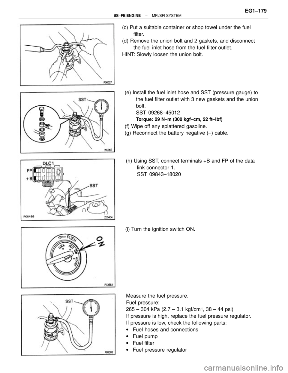
Measure the fuel pressure.
Fuel pressure:
265 ± 304 kPa (2.7 ± 3.1 kgf/cm�, 38 ± 44 psi)
If pressure is high, replace the fuel pressure regulator.
If pressure is low, check the following parts:
wFuel hoses and connections
wFuel pump
wFuel filter
wFuel pressure regulator (e) Install the fuel inlet hose and SST (pressure gauge) to
the fuel filter outlet with 3 new gaskets and the union
bolt.
SST 09268±45012
Torque: 29 N±m (300 kgf±cm, 22 ft±lbf)
(f) Wipe off any splattered gasoline.
(g) Reconnect the battery negative (±) cable. (c) Put a suitable container or shop towel under the fuel
filter.
(d) Remove the union bolt and 2 gaskets, and disconnect
the fuel inlet hose from the fuel filter outlet.
HINT: Slowly loosen the union bolt.
(h) Using SST, connect terminals +B and FP of the data
link connector 1.
SST 09843±18020
(i) Turn the ignition switch ON.
± 5S±FE ENGINEMFI/SFI SYSTEMEG1±179
Page 231 of 4770
 lead from the battery terminal 4 of the
connector, and the negative (±) lead
to terminal 5. Check that the fuel pump operates.
NOTICE:
wThese t")
B. Inspect fuel pump operation
Connect the positive (+) lead from the battery terminal 4 of the
connector, and the negative (±) lead
to terminal 5. Check that the fuel pump operates.
NOTICE:
wThese tests must be performed quickly (within 10
seconds) to prevent the coil from burning out.
wKeep the fuel pump a: far away from the battery as
possible.
wAlways perform switching at the battery side.
If operation is not as specified, replace the fuel pump.
5. RECONNECT FUEL PUMP & SENDER GAUGE
CONNECTOR
6. INSTALL REAR SEAT CUSHION
7. CONNECT NEGATIVE (±) TERMINAL CABLE TO
BATTERY
FUEL PUMP INSPECTION
1. DISCONNECT NEGATIVE (±) TERMINAL CABLE
FROM BATTERY
CAUTION: Work must be started after 90 seconds from
the time the Ignition switch Is turned to the 'LOCK'
position and the negative (±) terminal cable is discon±
nected from the battery.
4. INSPECT FUEL PUMP
A. Inspect fuel pump resistance
Using an ohmmeter, measure the resistance between
terminals 4 and 5.
Resistance (Cold):
0.2±3.0 W
If the resistance is not as specified, replace the fuel
pump. 2. REMOVE REAR SEAT CUSHION
3. DISCONNECT FUEL PUMP & SENDER GAUGE CON±
NECTOR
± 5S±FE ENGINEMFI/SFI SYSTEMEG1±181
Page 232 of 4770
1. DISCONNECT NEGATIVE (±) TERMINAL CABLE
FROM BATTERY
CAUTION: Work must be started after 90 seconds from
the time the ignition switch is turned to the ªLOCKº
position and the negative (±) terminal cable is discon±
nected from the battery.
2. REMOVE REAR SEAT CUSHION
FUEL PUMP REMOVAL
CAUTION: Do not smoke or work near an open flame
when working on the fuel pump.
COMPONENTS FOR REMOVAL AND
INSTALLATION
± 5S±FE ENGINEMFI/SFI SYSTEMEG1±182
 Using SST, connect terminals + B and FP of the data
link connector 1.
SST 09843±18020
(b) With engi")
 Using SST; connect terminals +B and FP of the data
link connector 1.
SST 09843±18020
(b) Turn the ignition switch ON.
NOTICE: Do not start the")
 Check that the battery voltages is above 12 volts.
(b) Disconnect the negative (±) terminal cable from the
battery.
CAUTION: Work must be started after 90 seconds from
the")
 TERMINAL CABLE
FROM BATTERY
CAUTION: Work must be started after 90 seconds from
the time the ignition switch is turned to the ªLOCKº
position and the negative (±) ter")