Page 59 of 4770
 and positive (+) of the battery.
Standa")
2. Except Delco Battery:
CHECK BATTERY VOLTAGE AND SPECIFIC
GRAVITY
A. Maintenance Free Battery
Measure the battery voltage between the terminals
negative (±) and positive (+) of the battery.
Standard voltage:
12.7 ± 12.9 V at 205C (685F)
HINT:
wBefore measuring the voltage, turn the ignition
switch to LOCK and turn off the electrical sys±
tems (headlight, blower motor, rear defogger etc.)
for 60 seconds to remove the surface charge.
wIf the vehicle has been running, wait 5 minutes or
more after the vehicle stops before measuring
the battery voltage.
If the voltage is less than specification, charge the
battery.
HINT: Check the indicator as shown in the illustration. 1. Except Delco Battery:
CHECK BATTERY ELECTROLYTE LEVEL
Check the electrolyte quantity of each cell.
A. Maintenance Free Battery
If under the lower level, replace the battery (or add
distilled water if possible). Check the charging system.
B. Except Maintenance Free Battery
If under the ªLOWERº or ªMINº line, add distilled
water.
BATTERY INSPECTION
± 5S±FE ENGINEENGINE MECHANICALEG1±9
Page 61 of 4770
 Visually check the drive belt for excessive wear,
frayed cords etc.
If any defect has been found, replace the drive belt.
HINT: Cracks on the rib")
GENERATOR DRIVE BELT INSPECTION
INSPECT DRIVE BELT
(a) Visually check the drive belt for excessive wear,
frayed cords etc.
If any defect has been found, replace the drive belt.
HINT: Cracks on the rib side of a drive belt are consid±
ered acceptable. If the drive belt has chunks missing
from the ribs, it should be replaced.4. INSPECT HIGH±TENSION CORD RESISTANCE
Using an ohmmeter, measure the resistance.
Maximum resistance:
25 k� per cord
If the resistance is greater than maximum, check the
terminals. If necessary, replace the high ± tension
cord.
5. RECONNECT HIGH±TENSION CORDS TO
DISTRIBUTOR CAP
6. CALIFORNIA ONLY:
RECONNECT HIGH±TENSION CORD TO IGNITION
COIL
7. RECONNECT HIGH±TENSION CORDS TO SPARK
PLUGS2. CALIFORNIA ONLY:
DISCONNECT HIGH±TENSION CORD FROM
IGNITION COIL
3. DISCONNECT HIGH ±TENSION CORDS FROM
DISTRIBUTOR CAP
(b) Using a belt tension gauge, measure the belt tension.
Belt tension gauge:
Nippondenso BTG±20 (95506±00020)
Borroughs No. BT±33±73F
± 5S±FE ENGINEENGINE MECHANICALEG1±11
Page 68 of 4770
2. CONNECT TACHOMETER AND TIMING LIGHT TO
ENGINE
Connect the test probe of a tachometer to terminal IG
(±) of the data link connector 1.
NOTICE:
wNEVER allow the tachometer terminal to touch
ground as it could result in damage to the igniter
and/or ignition coif.
wAs some tachometers are not compatible with this
Ignition system, we recommend that you confirm
the compatibility of yours before use.
3. ADJUST IGNITION TIMING
(a) Using SST, connect terminals TE1 and E1 of the data
link connector 1.
SST 09843±18020
HINT: After engine speed is kept at 1,000 ± 1,300
rpm for 5 seconds, check that it returns to idle speed.
IGNITION TIMING INSPECTION AND
ADJUSTMENT
1. WARM UP ENGINE
Allow the engine to warm up to normal operating
temperature.
(b) Using a timing light, check the ignition timing.
Ignition timing:
10
� BTDC @ idle
(Transmission in neutral position)
± 5S±FE ENGINEENGINE MECHANICALEG1±18
Page 69 of 4770
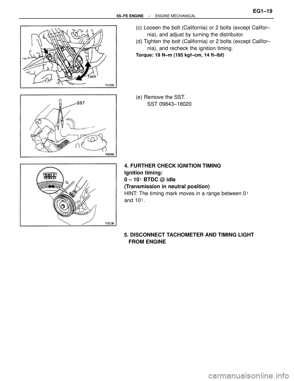
4. FURTHER CHECK IGNITION TIMING
Ignition timing:
0 ± 10� BTDC @ idle
(Transmission in neutral position)
HINT: The timing mark moves in a range between 0�
and 10�. (c) Loosen the bolt (California) or 2 bolts (except Califor±
nia), and adjust by turning the distributor.
(d) Tighten the bolt (California) or 2 bolts (except Califor±
nia), and recheck the ignition timing.
Torque: 19 N±m (195 kgf±cm, 14 ft±lbf)
5. DISCONNECT TACHOMETER AND TIMING LIGHT
FROM ENGINE(e) Remove the SST.
SST 09843±18020
± 5S±FE ENGINEENGINE MECHANICALEG1±19
Page 70 of 4770
 Engine at normal operating temperature
(b) Air cleaner installed
(c) All pipes and hoses of air induction system connected
(d) All vacuum lines properly")
IDLE SPEED INSPECTION
1. INITIAL CONDITIONS
(a) Engine at normal operating temperature
(b) Air cleaner installed
(c) All pipes and hoses of air induction system connected
(d) All vacuum lines properly connected
(e) MFI/SFI system wiring connectors fully plugged
(f) All operating accessories switched OFF
(g) Ignition timing set correctly
(h) Transmission in neutral position
2. CONNECT TACHOMETER
Connect the test probe of a tachometer to terminal IG
(±) of the data link connector 1.
NOTICE:
wNever allow the tachometer terminal to touch
ground as it could result in damage to the Igniter
and/or ignition coil.
wAs some tachometers are not compatible with this
ignition system, we recommend that you confirm
the compatibility of yours before use.
(b) Check the idle speed.
Idle speed (w/ Cooling fan OFF):
750+50 rpm
If the idle speed is not as specified, check the IAC
system.
4. DISCONNECT TACHOMETER 3. INSPECT IDLE SPEED
(a) Race the engine at 2,500 rpm for approx. 90 seconds.
± 5S±FE ENGINEENGINE MECHANICALEG1±20
Page 71 of 4770
 Engine at normal operating temperature
(")
IDLE AND OR 2,500 RPM CO/HC
CHECK
HINT: This check is used only to determine whether or
not the idle CO/HC complies with regulations.
1. INITIAL CONDITIONS
(a) Engine at normal operating temperature
(b) Air cleaner installed
(c) All pipes and hoses of air induction system connected
(d) All accessories switched OFF
(e) All vacuum lines properly connected
HINT: All vacuum hoses for EGR systems, etc. should
be properly connected.
(f) MFI/SFI system wiring connectors fully plugged
(g) Ignition timing set correctly
(h) Transmission in neutral position
(i) Tachometer and CO/HC meter calibrated by hand.
4. INSERT CO/HC METER TESTING PROBE AT LEAST
40 cm (1.3 ft) INTO TAILPIPE DURING IDLING
5. IMMEDIATTELY CHECK CO/HC CONCENTRATION
AT IDLE AND/OR 2,500 RPM
Complete the measuring within 3 minutes.
HINT: When performing the 2 mode (2,500 rpm and
idle) test, follow the measurement order prescribed by
the applicable local regulations. 2. START ENGINE
3. RACE ENGINE AT 2,500 RPM FOR APPROX. 180
SECONDS
± 5S±FE ENGINEENGINE MECHANICALEG1±21
Page 72 of 4770
 Check oxygen sensor operation.
(See page EG1±231)
(b) See the table")
Troubleshooting
If the CO/HC concentration does not comply with
regulations, perform troubleshooting in the order
given below.
(a) Check oxygen sensor operation.
(See page EG1±231)
(b) See the table below for possible causes, then inspect
and correct the applicable causes if necessary.
1. Faulty ignitions:
wIncorrect timing
wFouled, shorted or improperly gapped plugs
wOpen or crossed high±tension cords
wCracked distributor cap
2. Incorrect valve clearance
3. Leaky EGR valve
4. Leaky intake and exhaust valves
5. Leaky cylinder
1. Restricted air filter
2. Faulty MFI/SFI systems
wFaulty pressure regulator
wClogged fuel return line
wDefective engine coolant temp. sensor
wDefective intake air temp. sensor
wFaulty ECM
wFaulty injector
wFaulty throttle position sensor
wMAP sensor 1. Vacuum leaks:
wPCV hose
wEGR valve
wIntake manifold
wThrottle body
w!AC valve
wBrake booster line
2. Lean mixture causing misfire
Rough idle
(Black smoke from exhaust) Rough idle
(Fluctuating HC reading) Rough idleProblems
Causes
Normal
High High High
HighLow
± 5S±FE ENGINEENGINE MECHANICALEG1±22
Page 76 of 4770
TIMING BELT REMOVAL
(See Components for Removal and Installation)
1. DISCONNECT NEGATIVE (±) TERMINAL CABLE
FROM BATTERY
CAUTION: Work must be started after 90 seconds from
the time the ignition switch is turned to the 'LOCK'
position and the negative (±) terminal cable is discon±
nected from the battery.
2. REMOVE ENGINE COOLANT RESERVOIR TANK
(a) Disconnect the reservoir hose.
(b) While pushing the tab of the bracket, remove the
reservoir tank.
3. REMOVE GENERATOR (See page CH±10)
4. REMOVE RH FRONT WHEEL
5. REMOVE RH FENDER APRON SEAL
8. REMOVE ENGINE MOVING CONTROL ROD
Remove the 3 bolts and control rod.
9. DISCONNECT CONNECTOR FROM GROUND WIRE
ON RH FENDER APRON7. SLIGHTLY JACK UP ENGINE
Raise the engine enough to remove the weight from
the engine mounting on the right side. 6. REMOVE PS DRIVE BELT
Loosen the 2 bolts, and remove the drive belt.
± 5S±FE ENGINEENGINE MECHANICALEG1±26
 of the data link connector 1.
NOTICE:
wNEVER allow the tachometer terminal to touch
ground a")

1. DISCONNECT NEGATIVE (±) TERMINAL CABLE
FROM BATTERY
CAUTION: Work must be started after 90 seconds from
the time the ignition swit")