Page 2320 of 4770

Terminal
Rectifire
Terminal
P00481
OhmmeterNegative (±)
Treminal CH±10
± CHARGING (1MZ±FE)GENERATOR
1773 Author�: Date�:
3. INSPECT BRUSHES
Using a vernie")
P13535
Length
P00480
OhmmeterPositive (+)
Terminal
Rectifire
Terminal
P00481
OhmmeterNegative (±)
Treminal CH±10
± CHARGING (1MZ±FE)GENERATOR
1773 Author�: Date�:
3. INSPECT BRUSHES
Using a vernier caliper, measure the exposed brush length.
Standard exposed length: 10.5 mm (0.413 in.)
Minimum exposed length: 1.5 mm (0.059 in.)
If the exposed length is less than minimum, replace the brushes
and brush holder assembly.
4. INSPECT RECTIFIERS (RECTIFIRE HOLDER)
(a) Check the positive (+) rectifire.
(1) Using an ohmmeter, connect one tester probe to the
positive (+) terminal and the other to each rectifier
terminal.
(2) Reverse the polarity of the tester probes and repeat
step (a).
(3) Check that one shows continuity and the other
shows no continuity.
If continuity is not as specified, replace the rectifier holder.
(b) Check the negative (±) rectifire.
(1) Using an ohmmeter, connect one tester probe to
each negative (±) terminal and the other to each
rectifier terminal.
(2) Reverse the polarity of the tester probes and repeat
step (a).
(3) Check that one shows continuity and the other
shows no continuity.
If continuity is not as specified, replace the rectifier holder.
5. INSPECT BEARING
Check the bearing is not rough or worn.
If necessary, replace the bearing. (See page CH±11)
Page 2321 of 4770
CH01I±01
P14225
P00628
Socket Wrench
P00479
SST
N00581
SST
P13567
± CHARGING (1MZ±FE)GENERATOR
CH±11
1774 Author�: Date�:
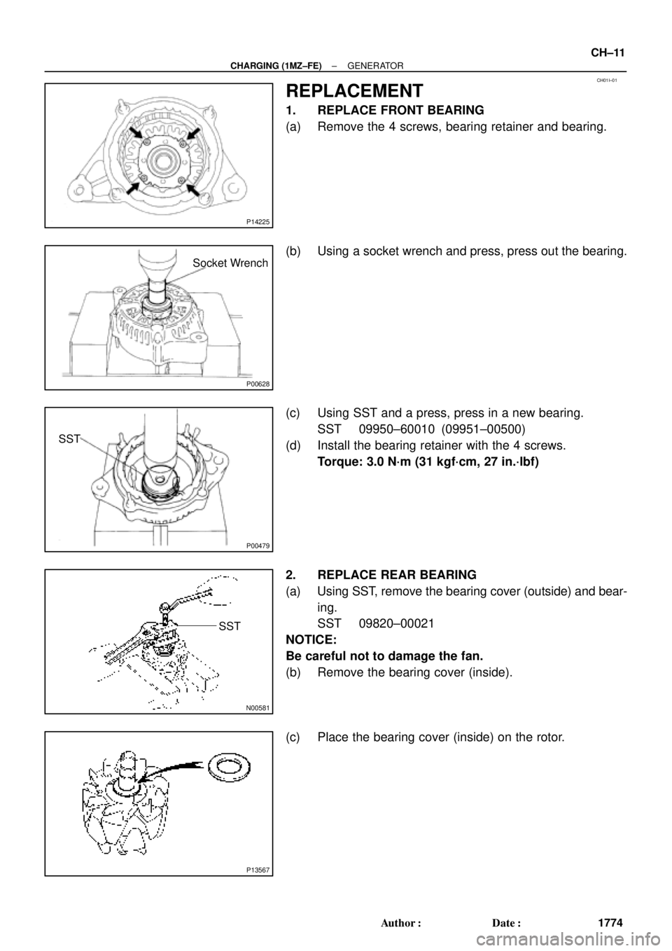
REPLACEMENT
1. REPLACE FRONT BEARING
(a) Remove the 4 screws, bearing retainer and bearing.
(b) Using a socket wrench and press, press out the bearing.
(c) Using SST and a press, press in a new bearing.
SST 09950±60010 (09951±00500)
(d) Install the bearing retainer with the 4 screws.
Torque: 3.0 N´m (31 kgf´cm, 27 in.´lbf)
2. REPLACE REAR BEARING
(a) Using SST, remove the bearing cover (outside) and bear-
ing.
SST 09820±00021
NOTICE:
Be careful not to damage the fan.
(b) Remove the bearing cover (inside).
(c) Place the bearing cover (inside) on the rotor.
Page 2322 of 4770
N00578
SST
P00074
SST
CH±12
± CHARGING (1MZ±FE)GENERATOR
1775 Author�: Date�:
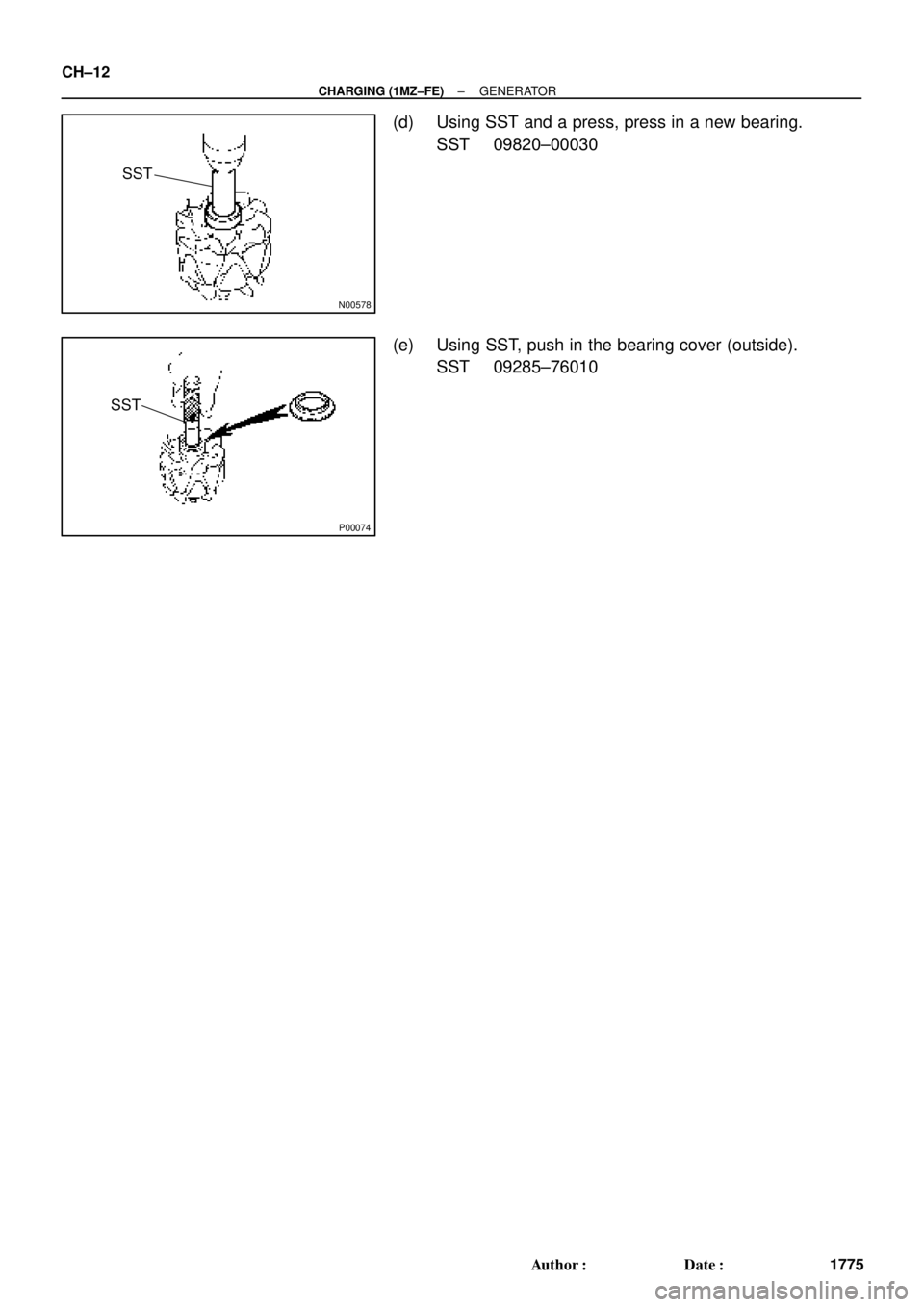
(d) Using SST and a press, press in a new bearing.
SST 09820±00030
(e) Using SST, push in the bearing cover (outside).
SST 09285±76010
Page 2323 of 4770
CH01J±01
P01364
Pulley
P00427
P01763
29 mm
Socket
Wrench
Z19214AA A
B
P10835
Turn
SST (A)
SST (B)
± CHARGING (1MZ±FE)GENERATOR
CH±13
1776 Author�: Date�:
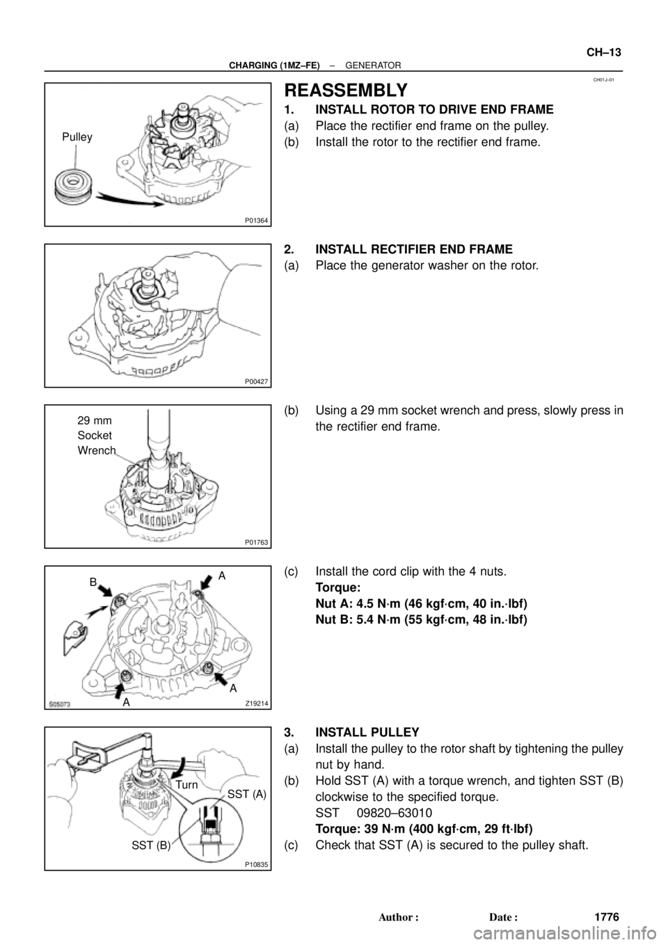
REASSEMBLY
1. INSTALL ROTOR TO DRIVE END FRAME
(a) Place the rectifier end frame on the pulley.
(b) Install the rotor to the rectifier end frame.
2. INSTALL RECTIFIER END FRAME
(a) Place the generator washer on the rotor.
(b) Using a 29 mm socket wrench and press, slowly press in
the rectifier end frame.
(c) Install the cord clip with the 4 nuts.
Torque:
Nut A: 4.5 N´m (46 kgf´cm, 40 in.´lbf)
Nut B: 5.4 N´m (55 kgf´cm, 48 in.´lbf)
3. INSTALL PULLEY
(a) Install the pulley to the rotor shaft by tightening the pulley
nut by hand.
(b) Hold SST (A) with a torque wrench, and tighten SST (B)
clockwise to the specified torque.
SST 09820±63010
Torque: 39 N´m (400 kgf´cm, 29 ft´lbf)
(c) Check that SST (A) is secured to the pulley shaft.
Page 2324 of 4770
P10834
SST (C)SST (A)
Insert
P10829
SST (C)
SST (A)
Turn
P10836
SST (B)SST (A) Turn
P00428
P00645
CH±14
± CHARGING (1MZ±FE)GENERATOR
1777 Author�: Date�:
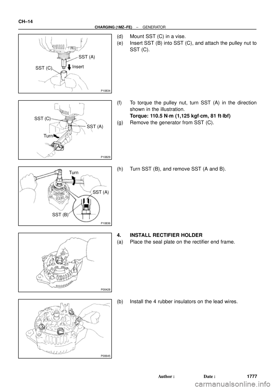
(d) Mount SST (C) in a vise.
(e) Insert SST (B) into SST (C), and attach the pulley nut to
SST (C).
(f) To torque the pulley nut, turn SST (A) in the direction
shown in the illustration.
Torque: 110.5 N´m (1,125 kgf´cm, 81 ft´lbf)
(g) Remove the generator from SST (C).
(h) Turn SST (B), and remove SST (A and B).
4. INSTALL RECTIFIER HOLDER
(a) Place the seal plate on the rectifier end frame.
(b) Install the 4 rubber insulators on the lead wires.
Page 2325 of 4770
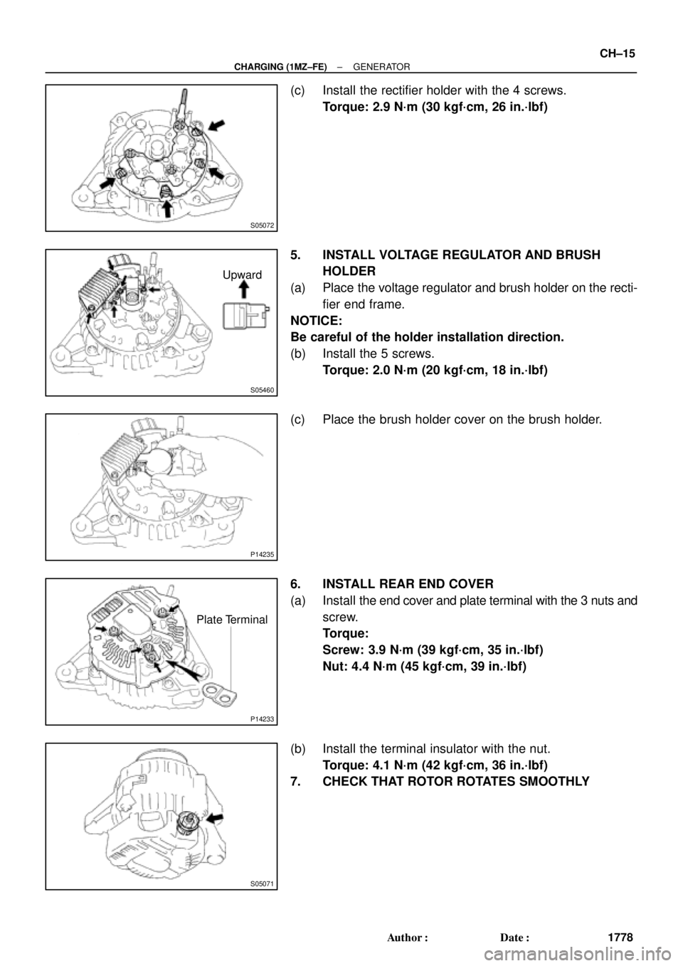
S05072
S05460
Upward
P14235
P14233
Plate Terminal
S05071
± CHARGING (1MZ±FE)GENERATOR
CH±15
1778 Author�: Date�:
(c) Install the rectifier holder with the 4 screws.
Torque: 2.9 N´m (30 kgf´cm, 26 in.´lbf)
5. INSTALL VOLTAGE REGULATOR AND BRUSH
HOLDER
(a) Place the voltage regulator and brush holder on the recti-
fier end frame.
NOTICE:
Be careful of the holder installation direction.
(b) Install the 5 screws.
Torque: 2.0 N´m (20 kgf´cm, 18 in.´lbf)
(c) Place the brush holder cover on the brush holder.
6. INSTALL REAR END COVER
(a) Install the end cover and plate terminal with the 3 nuts and
screw.
Torque:
Screw: 3.9 N´m (39 kgf´cm, 35 in.´lbf)
Nut: 4.4 N´m (45 kgf´cm, 39 in.´lbf)
(b) Install the terminal insulator with the nut.
Torque: 4.1 N´m (42 kgf´cm, 36 in.´lbf)
7. CHECK THAT ROTOR ROTATES SMOOTHLY
Page 2326 of 4770
CH01K±01
CH±16
± CHARGING (1MZ±FE)GENERATOR
1779 Author�: Date�:
INSTALLATION
Installation is in the reverse order of removal. (See page ST±5)
Page 2917 of 4770

DI±497
732 Author�: Date�:
DIAGNOSTIC TROUBLE CODE CHART
HINT:
�Using SST 09843 ±18020, connect the terminals Tc and E1, and remove the s")
DI03D±03
± DIAGNOSTICSANTI±LOCK BRAKE SYSTEM (DENSO Made)
DI±497
732 Author�: Date�:
DIAGNOSTIC TROUBLE CODE CHART
HINT:
�Using SST 09843 ±18020, connect the terminals Tc and E1, and remove the short pin.
�If any abnormality is not found when inspection parts, inspect the ECU.
�If a malfunction code is displayed during the DTC check, check the circuit listed for the code. For details
of each code, turn to the page referred to under the ºSee pageº for respective ºDTC No.º in the DTC
chart.
DTC No.
(See Page)Detection ItemTrouble Area
11
(DI±502)Open circuit in ABS solenoid relay circuit�ABS solenoid relay
12
(DI±502)Short circuit in ABS solenoid relay circuit
�ABS solenoid relay
�ABS solenoid relay circuit
13
(DI±507)Open circuit in ABS motor relay circuit�ABS motor relay
14
(DI±507)Short circuit in ABS motor relay circuit
�ABS motor relay
�ABS motor relay circuit
21
(DI±511)Open or short circuit in 2±position solenoid circuit for right front
wheel�ABS actuator
�SFRR or SFRH circuit
22
(DI±511)Open or short circuit in 2±position solenoid circuit for left front
wheel�ABS actuator
�SFLR or SFLH circuit
23
(DI±511)Open or short circuit in 2±position solenoid circuit for right rear
wheel�ABS actuator
�SRRR or SRRH circuit
24
(DI±511)Open or short circuit in 2±position solenoid circuit for left rear
wheel�ABS actuator
�SRLR or SRLH circuit
31
(DI±514)Right front wheel speed sensor signal malfunction
32
(DI±514)Left front wheel speed sensor signal malfunction�Right front, left front, right rear and left rear speed sensor
Eh d i it33
(DI±514)Right rear wheel speed sensor signal malfunction
�Each speed sensor circuit
�Speed sensor rotor
34
(DI±514)Left rear wheel speed sensor signal malfunction
33, 34
(DI±519)Rear speed sensor rotor faulty
�Rear axle hub
�Right rear, left rear speed sensor
�Rear speed sensor circuit
41
(DI±520)Power source voltage down
�Battery
�Charging system
�Power source circuit
49
(DI±523)Open circuit in stop light switch circuit�Stop light switch
�Stop light switch circuit
51
(DI±525)Pump motor is locked�ABS pump motor
Always ON
(DI±527)Malfunction in ECU�ECU
�Battery