Page 3019 of 4770
F00073
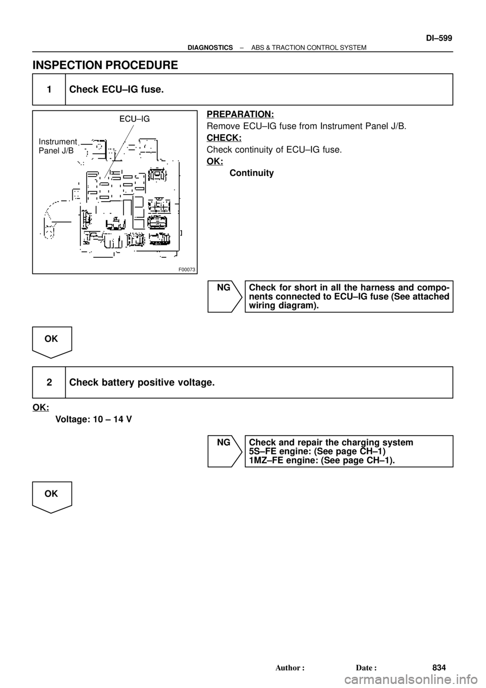
ECU±IGECU±IG
Instrument
Panel J/BECU±IG
± DIAGNOSTICSABS & TRACTION CONTROL SYSTEM
DI±599
834 Author�: Date�:
INSPECTION PROCEDURE
1 Check ECU±IG fuse.
PREPARATION:
Remove ECU±IG fuse from Instrument Panel J/B.
CHECK:
Check continuity of ECU±IG fuse.
OK:
Continuity
NG Check for short in all the harness and compo-
nents connected to ECU±IG fuse (See attached
wiring diagram).
OK
2 Check battery positive voltage.
OK:
Voltage: 10 ± 14 V
NG Check and repair the charging system
5S±FE engine: (See page CH±1)
1MZ±FE engine: (See page CH±1).
OK
Page 3031 of 4770
± DIAGNOSTICSABS & TRACTION CONTROL SYSTEM
DI±611
846 Author�: Date�:
4 Check battery positive voltage.
CHECK:
Check the battery positive voltage.
OK:
10 ± 14 V
NG Check and repair the charging system
5S±FE engine: (See page CH±1)
1MZ±FE engine: (See page CH±1).
OK
5 Check ABS warning light.
PREPARATION:
(a) Disconnect the connector from the ABS & TRAC ECU.
(b) Turn the ignition switch ON.
CHECK:
Check the ABS warning light goes off.
OK Check and replace ABS & TRAC ECU.
NG
Check for short circuit in harness and connector between ABS warning light, DLC1, DLC2, and
ABS & TRAC ECU (See page IN±31)
Page 3176 of 4770
 (+)ONAirbag Sensor Assembly
ACC
IG2
DI±756
± DIAGNOSTICSSUPPLEMENTAL RESTRAINT SYSTEM
991 Author�: Date�:
DTC B1100/31 Airbag Sensor Assembly Malfunction
CIRCUIT DESCRIPTION")
AB0119H01298H01299
(±) (+)ONAirbag Sensor Assembly
ACC
IG2
DI±756
± DIAGNOSTICSSUPPLEMENTAL RESTRAINT SYSTEM
991 Author�: Date�:
DTC B1100/31 Airbag Sensor Assembly Malfunction
CIRCUIT DESCRIPTION
The airbag sensor assembly consists of a airbag sensor, safing sensor, drive circuit, diagnosis circuit and
ignition control, etc.
It receives signals from the airbag sensor, judges whether or not the SRS must be activated, and detects
diagnosis system malfunction.
DTC B1100/31 is recorded when occurrence of a malfunction in the airbag sensor assembly is detected.
DTC No.DTC Detecting ConditionTrouble Area
B1100/31�Airbag sensor assembly malfunction�Airbag sensor assembly
INSPECTION PROCEDURE
HINT:
When a malfunction code other than code B1100/31 is displayed at the same time, first repair the malfunction
indicated by the malfunction code other than code B1100/31.
1 Prepare for inspection. (See step 1 on page DI±787)
2 Check voltage at IG2 and ACC of airbag sensor assembly.
CHECK:
(a) Turn ignition switch to ON.
(b) Measure the voltage between body ground and terminals
each of IG2 and ACC of the airbag sensor assembly con-
nector.
OK:
Voltage: 10 ± 14 V
NG Check that an abnormality occurs on the battery
and charging system.
OK
DI1BM±18
Page 3209 of 4770
 (±)
H01249
ON
± DIAGNOSTICSSUPPLEMENTAL RESTRAINT SYSTEM
DI±789
1024 Author�: Date�:
2 Check source voltage.
PREPARATION:
Connect negative")
AB0119H01298H01299
Airbag Sensor Assembly
ON
ACC
IG2
(+) (±)
H01249
ON
± DIAGNOSTICSSUPPLEMENTAL RESTRAINT SYSTEM
DI±789
1024 Author�: Date�:
2 Check source voltage.
PREPARATION:
Connect negative (±) terminal cable to the battery.
CHECK:
(a) Turn ignition switch ON.
(b) Measure the voltage each of IG2 and ACC on the sensor
and operate electric system. (defogger, wiper, headlight,
heater blower, etc.)
OK:
Voltage: 10 ± 14 V
NG Check harness between battery and airbag sen-
sor assembly, and check battery and charging
system.
OK
3 Does SRS warning light turn off?
PREPARATION:
(a) Turn ignition switch to LOCK.
(b) Connect the steering wheel pad connector.
(c) Connect the front passenger airbag assembly connector.
(d) Connect the airbag sensor assembly connectors.
(e) Connect the side airbag assembly connectors.
(f) Connect the seat belt pretensioner connectors.
(g) Connect the side airbag sensor assembly connectors.
(h) Connect the front airbag sensor connectors.
(i) Turn ignition switch to ON.
CHECK:
Operate electric system (defogger, wiper, headlight, heater
blower, etc.) and check that SRS warning light goes off.
NO Check for DTCs. If a DTC is output, perform trou-
bleshooting for the DTC. If a normal code is out-
put, replace airbag sensor assembly.
YES
From the results of the above inspection, the malfunctioning part can now be considered normal.
To make sure of this, use the simulation method to check.
Page 3903 of 4770
PP0KD±01
PP±52
± PREPARATIONCHARGING (5S±FE)
104 Author�: Date�:
CHARGING(5S±FE)
SST (Special Service Tools)
09285±76010Injection Pump Camshaft Bearing
Cone ReplacerRotor rear bearing cover
09286±46011Injection Pump Spline Shaft
PullerRectifier end frame
09820±00021Alternator Rear Bearing Puller
09820±00030Alternator Rear Bearing ReplacerRotor rear bearing
09820±63010Alternator Pulley Set Nut Wrench
Set
09950±60010Replacer Set
(09951±00500)Replacer 50Rotor front bearing
Page 3904 of 4770
PP0KE±01
± PREPARATIONCHARGING (5S±FE)
PP±53
105 Author�: Date�:
RECOMMENDED TOOLS
09082±00040TOYOTA Electrical Tester.
Page 3905 of 4770
PP0KF±01
PP±54
± PREPARATIONCHARGING (5S±FE)
106 Author�: Date�:
EQUIPMENT
Battery specific gravity gaugeExcept maintenance free battery
Belt tension gauge
Torque wrench
Vernier calipersRotor (Slip ring), Brush
Page 3906 of 4770
PP0CC±01
± PREPARATIONCHARGING (1MZ±FE)
PP±55
107 Author�: Date�:
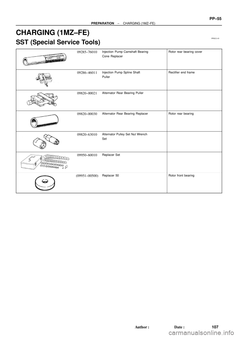
CHARGING (1MZ±FE)
SST (Special Service Tools)
09285±76010Injection Pump Camshaft Bearing
Cone ReplacerRotor rear bearing cover
09286±46011Injection Pump Spline Shaft
PullerRectifier end frame
09820±00021Alternator Rear Bearing Puller
09820±00030Alternator Rear Bearing ReplacerRotor rear bearing
09820±63010Alternator Pulley Set Nut Wrench
Set
09950±60010Replacer Set
(09951±00500)Replacer 50Rotor front bearing