Page 3907 of 4770
PP0CD±01
PP±56
± PREPARATIONCHARGING (1MZ±FE)
108 Author�: Date�:
RECOMMENDED TOOLS
09082±00040TOYOTA Electrical Tester.
Page 3908 of 4770
PP0CE±02
± PREPARATIONCHARGING (1MZ±FE)
PP±57
109 Author�: Date�:
EQUIPMENT
Ammeter(A)
Battery specific gravity gaugeExcept maintenance free battery
Belt tension gauge
Torque wrench
Vernier calipersRotor (Slip ring), Brush
Page 3958 of 4770
PP1XJ±01
± PREPARATIONAIR CONDITIONING
PP±107
159 Author�: Date�:
AIR CONDITIONING
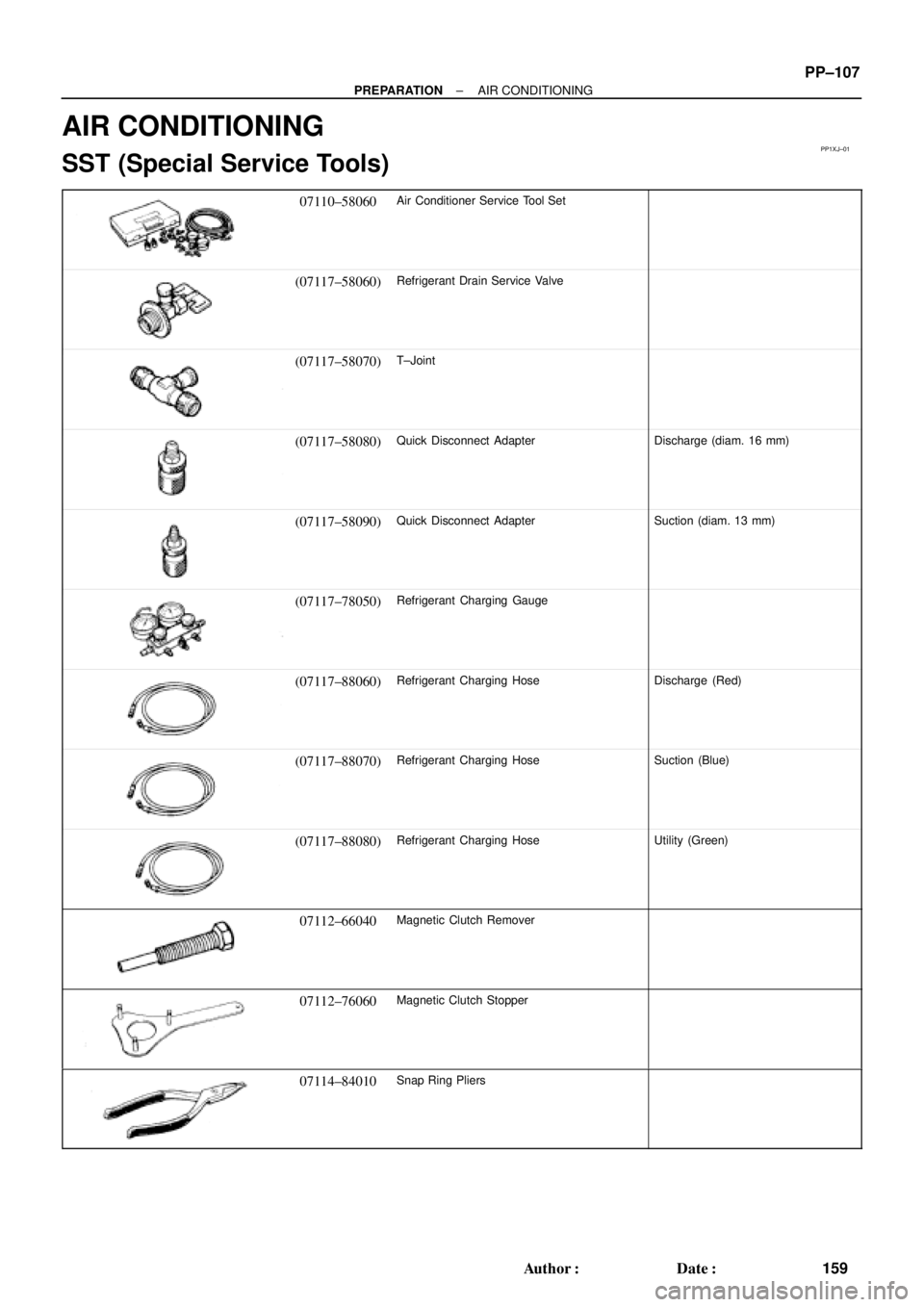
SST (Special Service Tools)
07110±58060Air Conditioner Service Tool Set
(07117±58060)Refrigerant Drain Service Valve
(07117±58070)T±Joint
(07117±58080)Quick Disconnect AdapterDischarge (diam. 16 mm)
(07117±58090)Quick Disconnect AdapterSuction (diam. 13 mm)
(07117±78050)Refrigerant Charging Gauge
(07117±88060)Refrigerant Charging HoseDischarge (Red)
(07117±88070)Refrigerant Charging HoseSuction (Blue)
(07117±88080)Refrigerant Charging HoseUtility (Green)
07112±66040Magnetic Clutch Remover
07112±76060Magnetic Clutch Stopper
07114±84010Snap Ring Pliers
Page 4001 of 4770
SS0AQ±01
± SERVICE SPECIFICATIONSCHARGING (5S±FE)
SS±39
202 Author�: Date�:
CHARGING(5S±FE)
SERVICE DATA
BatterySpecific gravity (Except maintenance±free battery)
at 20°C (68°F)
Voltage (Maintenance±free battery) at 20°C (68°F)
1.25 ± 1.29
12.5 ± 12.9 V
Drive beltTension w/ A/C New belt
Used belt
w/o A/C New belt
Used belt165 ± 25 lbf
110 ± 10 lbf
125 ± 25 lbf
95 ± 20 lbf
GeneratorRated output
Rotor coil resistance at 20°C (68°F)
Slip ring diameter STD
Minimum
Brush exposed length STD
Minimum12 V 80 A
2.7 ± 3.1 W
14.2 ± 14.4 mm (0.559 ± 0.567 in.)
12.8 mm (0.504 in.)
10.5 mm (0.413 in.)
1.5 mm (0.059 in.)
Voltage
regulatorRegulating voltage13.5 ± 15.1 V
Page 4002 of 4770
SS0AR±01
SS±40
± SERVICE SPECIFICATIONSCHARGING (5S±FE)
203 Author�: Date�:
TORQUE SPECIFICATION
Part tightenedN´mkgf´cmft´lbf
Bearing retainer x Drive end frame3.03127 in.´lbf
Rectifier end frame x Drive end frame4.54640 in.´lbf
Wire clip x Rectifier end frame5.45548 in.´lbf
Generator pulley x Rotor110.51,12581
Rectifier holder x Coil lead on rectifier end frame2.93026 in.´lbf
Voltage regulator x Rectifier end flame2.02018 in.´lbf
Voltage regulator x Rectifier holder2.02018 in.´lbf
Brush holder x Rectifier holder2.02018 in.´lbf
Brush holder x Voltage regulator2.02018 in.´lbf
Rear end cover x Rectifier holder4.44539 in.´lbf
Plate terminal x Rectifier holder Nut
Bolt4.4
3.945
3939 in.´lbf
35 in.´lbf
Terminal insulator x Rectifier holder4.14236 in.´lbf
Generator x Generator bracket5253038
Generator x Adjusting bar1818513
Page 4003 of 4770
SS07K±01
± SERVICE SPECIFICATIONSCHARGING (1MZ±FE)
SS±41
204 Author�: Date�:
CHARGING (1MZ±FE)
SERVICE DATA
BatteryVoltage at 20°C (68°F)12.5 ± 12.9 V
Drive belt
Tension
New belt
Used belt
175 ± 5 lbf
115 ± 20 lbf
GeneratorRated output
Rotor coil resistance at 20°C (68°F)
Slip ring diameter STD
Limit
Brush exposed length STD
Limit12 V 80 A
2.1 ± 2.5 W
14.2 ± 14.4 mm (0.559 ± 0.567 in.)
12.8 mm (0.504 in.)
10.5 mm (0.413 in.)
1.5 mm (0.059 in.)
Voltage
regulatorRegulating voltage13.5 ± 15.1 V
Page 4004 of 4770
SS07L±01
SS±42
± SERVICE SPECIFICATIONSCHARGING (1MZ±FE)
205 Author�: Date�:
TORQUE SPECIFICATION
Part tightenedN´mkgf´cmft´lbf
Bearing retainer x Drive end frame3.03127 in.´lbf
Rectifier end frame x Drive end frame4.54640 in.´lbf
Cord clip x Rectifier end frame5.45548 in.´lbf
Generator pulley x Rotor110.51,12581
Rectifier holder x Coil lead on rectifier end frame2.93026 in.´lbf
Voltage regulator and brush holder x Rectifier end frame2.02018 in.´lbf
Plate terminal x Rectifier holder Nut
Screw4.4
3.945
3939 in.´lbf
35 in.´lbf
Rear end cover x Rectifier holder4.44539 in.´lbf
Terminal insulator x Rectifier holder4.14236 in.´lbf
Generator x Generator bracket5657041
Generator x Adjusting bar1818013
Page 4587 of 4770

Toyota Supports ASE CertificationPage 1 of 1
EL006±99Title:
ENGINE IMMOBILIZER SYSTEM
PRECAUTIONS
Models:
All Models
Technical Service
BULLETIN
October 8, 1999
REVISION NOTICE:
The information contained in this TSB updates EL001±98 dated January 23, 1998.
This bulletin applies to 1998 and newer Toyota vehicles. When using an immobilizer key
containing a transponder chip, observe the following precautions while starting the engine.
1. The key ring should not
rest on or be
pressed against the key grip.
2. Do not
place any other transponder
devices on the same key ring. Such
devices would include transponder
equipped units used for charging fuel.
3. Do not
place any other immobilizer
keys on the same key ring with the
key used to start the vehicle.
4. If the above precautions are not
observed and an engine starting or
running problem occurs, remove all
items which may interfere with the
ignition key transponder signal. Turn
off the engine and then restart.
�All Toyota models equipped with an engine immobilizer system.
OP CODEDESCRIPTIONTIMEOPNT1T2
N/ANot Applicable to Warranty±±±±
ELECTRICAL
Introduction
Applicable
Vehicles
Warranty
Information